






Showing all 12 results

Filter by price
Filter by brands

- National Instruments
- PCI ModulesPCI Modules
- PXI Systems
- PXI Chassis
- PXI Controller
- PXI Modules
- PXI Semiconductor Test
- PXI FPGA and RIO Modules
- PXI MXI Interfaces
- PXI Programmable Power Supplies & SMU
- PXI Sensor Measurements
- PXI Signal Generators
- PXI Vision
- PXI Data Acquisition
- PXI Oscilloscopes/Digitizers
- PXI Counter/Timers
- PXI RF and Wireless Test
- PXI GPIB, Ethernet and VXI
- PXI Switches
- PXI Digital Multimeters
- PXI Digital Input/Output
- PXI Industrial Communication
- PXI Dynamic Signal Analysis
- PXI Data Streaming
- CompactDAQ Systems
- CompactRIO Systems
- PCI Modules
- USB Devices
- USRP Software Defined Radio Device
- keysight
- Tektronix
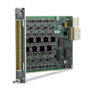
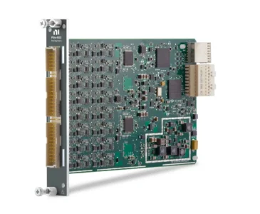
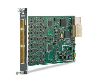
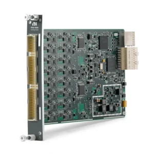
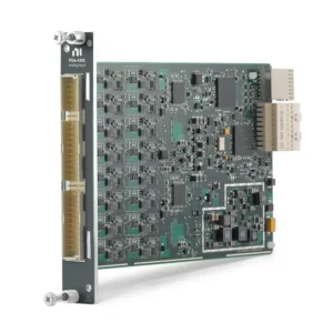
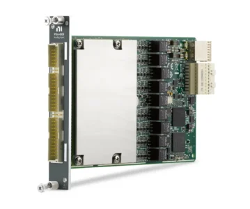
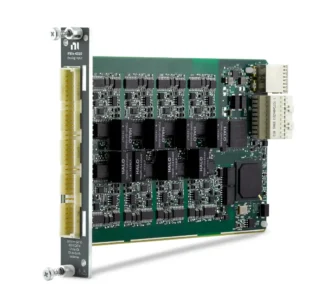
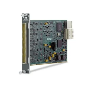
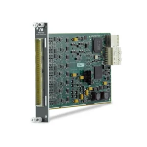
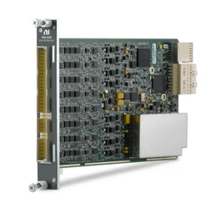
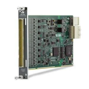
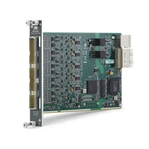
NI PXI Sensor Measurement Modules
NI PXI Sensor Measurement modules combine data acquisition with measurement-specific signal conditioning for thermocouples, RTDs, strain gauges, load cells, pressure transducers, torque sensors, microphones, accelerometers and LVDT/RVDT position sensors. Unlike general-purpose voltage acquisition modules, these devices can provide the excitation, bridge completion, cold-junction compensation, filtering, sensor scaling and diagnostic functions required to connect supported sensors directly to a PXI system.
Module selection should begin with the sensor’s electrical output rather than the physical quantity being measured. Engineers must match the input architecture, excitation, voltage or mV/V range, bandwidth, sample rate, isolation and synchronization to the sensor and test objective. Procurement teams should also verify the terminal block, cable, connector, driver version, calibration requirements and PXI chassis compatibility.
How PXI Sensor Measurement Systems Work
A sensor measurement chain includes the sensor, excitation source, signal conditioning, analog-to-digital converter, wiring, measurement software and engineering-unit scaling. An incorrect choice in any part of this chain can introduce offset, noise, drift, phase error or sensor damage even when the PXI module itself meets its specifications.
PXI sensor modules install in a compatible NI PXI system and use PXI timing and triggering resources to coordinate measurements with other instruments. This is useful when temperature, strain, force, vibration, voltage and control signals must be acquired as part of the same automated test.
PXI Sensor Measurement Types
| Measurement Type | Typical Sensor Output | Required Signal Conditioning | Primary Selection Criteria |
|---|---|---|---|
| Thermocouple | Low-level voltage related to temperature difference | Cold-junction compensation, amplification, noise rejection and open-sensor detection | Thermocouple type, temperature range, accuracy, channel count and isolation |
| RTD | Resistance that changes with temperature | Precision excitation, resistance measurement and lead-wire compensation | 2-, 3- or 4-wire configuration, RTD type, excitation and self-heating |
| Strain, Load, Pressure and Torque | Low-level ratiometric Wheatstone-bridge output | Bridge excitation, completion, remote sensing, filtering and shunt calibration | Bridge configuration, resistance, mV/V range, excitation and bandwidth |
| Sound and Vibration | Voltage, IEPE or charge output | Constant-current excitation, AC/DC coupling, anti-alias filtering and sensor scaling | Sensor type, frequency range, dynamic range, sample rate and simultaneous sampling |
| Position and Displacement | Amplitude- and phase-modulated AC signal from an LVDT or RVDT | AC excitation, demodulation, filtering and ratio measurement | Sensor excitation, sensitivity, frequency, travel range and channel count |
| Conditioned Sensor Voltage | Standard voltage or current from an external conditioner | Input range, filtering and isolation; external conditioning is already provided | Signal range, source impedance, bandwidth and grounding arrangement |
The measured physical quantity does not uniquely identify the required module. A pressure sensor may use a bridge output, conditioned voltage, current loop, charge output or digital interface. Always obtain the sensor datasheet and identify its electrical interface before selecting PXI hardware.
Representative NI PXI Sensor Measurement Modules
| Model | Unique Category | Core Architecture | Best Fit |
|---|---|---|---|
| PXIe-4353 | Thermocouple Input | 32-channel, 24-bit thermocouple measurement with bank isolation, cold-junction compensation support and open-thermocouple detection | High-channel-count thermal testing and temperature logging |
| PXIe-4357 | RTD Input | 20-channel, 24-bit input for 2-, 3- and 4-wire RTD measurements | Precision resistance-based temperature measurement |
| PXIe-4330 | General-Purpose Bridge Input | Eight simultaneously sampled, 24-bit bridge channels at up to 25.6 kS/s per channel | Static and moderately dynamic strain, load, force and pressure measurement |
| PXIe-4331 | High-Speed Bridge Input | Eight simultaneously sampled bridge channels with rates up to 102.4 kS/s per channel | Dynamic structural, impact and high-bandwidth bridge measurements |
| PXIe-4339 | Universal Bridge Input | Eight 24-bit, 25.6 kS/s simultaneous channels with per-channel bridge configuration, excitation and direct voltage modes | Test cells using mixed bridge sensors and changing measurement configurations |
| PXIe-4340 | LVDT/RVDT Input | Four simultaneous 24-bit AC LVDT/RVDT channels operating at up to 25.6 kS/s per channel | Linear and rotary position, displacement and motion measurement |
| PXIe-4468 | Precision Sound and Vibration I/O | Two analog inputs and two analog outputs with IEPE conditioning, AC/DC coupling and 250 kS/s input sampling | Precision audio, acoustic, vibration and stimulus-response testing |
| PXIe-4480 | High-Bandwidth Dynamic Input | Six simultaneous inputs with IEPE, charge, voltage excitation, TEDS and high-bandwidth acquisition modes | NVH, acoustic, pressure, hydrophone and transient-event measurements |
This table represents the major measurement architectures rather than every legacy or specialized NI model. Verify the exact part number, hardware revision, accessory and driver support before ordering.
How to Select a PXI Sensor Measurement Module
1. Identify the Sensor’s Electrical Output
Start with the sensor datasheet and determine whether the output is thermocouple voltage, RTD resistance, bridge mV/V, IEPE, charge, LVDT/RVDT, conditioned voltage or current. Sensors measuring the same physical parameter may require completely different input hardware.
Also record the nominal output, maximum output, source impedance, excitation requirement, connector, grounding arrangement and calibration sensitivity. A module supporting the physical measurement type may still be unsuitable if its excitation or input range does not match the sensor.
2. Match Signal Conditioning and Excitation
Low-level sensors normally require more than an analog-to-digital converter. Thermocouples need cold-junction compensation; RTDs require precision current excitation; strain gauges need bridge excitation and completion; IEPE sensors require constant-current power; and LVDT/RVDT sensors require AC excitation and demodulation.
Check whether these functions are integrated into the module or provided by a terminal block or external conditioner. Do not connect an externally powered sensor to an excitation output until the wiring and voltage limits have been verified.
3. Select the Input Range for the Actual Signal
The smallest input range that accommodates the maximum expected signal generally provides better effective resolution. For bridge sensors, compare the sensor’s rated output in mV/V with the module’s ratiometric ranges. For voltage-output sensors, include sensor offset, overload conditions and common-mode voltage when selecting the range.
ADC resolution alone does not determine usable measurement resolution. Input noise, gain error, offset, excitation stability, sensor sensitivity and environmental interference must also be considered.
4. Determine Bandwidth and Sample Rate
Temperature monitoring may require only a few samples per second, while impact, vibration and acoustic testing can require tens of thousands or millions of samples per second. Select the measurement bandwidth first, then confirm that the module’s sample rate and anti-alias filtering support that bandwidth.
Maximum sample rate and usable bandwidth are not identical. Delta-sigma modules include digital filtering that improves noise and alias rejection but introduces group delay. Applications involving feedback, transient timing or correlation with other instruments should account for this delay.
5. Evaluate Simultaneous Sampling and Synchronization
Simultaneous sampling is important when phase relationships must be preserved between vibration, strain, force or pressure channels. Multiplexed temperature modules are suitable for slower measurements but do not acquire every channel at exactly the same instant.
For mixed-module tests, confirm how sample clocks, start triggers and reference clocks will be shared. Synchronization should be designed for the complete system rather than assumed from the use of a common chassis.
6. Review Isolation and Grounding
Isolation helps manage common-mode voltage and ground-potential differences, but the isolation topology matters. Bank-isolated channels share a reference within each bank, while channel-to-channel isolation gives each channel an independent electrical reference.
Sound and vibration modules are often non-isolated and depend on correct sensor grounding and cable shielding. Grounded sensors, long cable runs and machinery installations should be reviewed for ground loops before hardware is ordered.
7. Calculate the Complete Accuracy Budget
A complete accuracy calculation may include sensor tolerance, calibration uncertainty, module gain and offset errors, excitation accuracy, cold-junction compensation, lead-wire resistance, noise, temperature drift and scaling uncertainty. Published ADC resolution should not be used as the system accuracy specification.
For long-duration or regulated tests, also confirm the module calibration interval, sensor calibration data, traceability requirements and the method used to store or apply calibration coefficients.
Temperature Measurement Considerations
Thermocouple Systems
Thermocouples produce a small voltage based on the temperature difference between the measurement junction and the reference junction. The selected system must support the required thermocouple type and provide accurate cold-junction compensation at the point where thermocouple wire connects to copper terminals.
Terminal-block thermal design, extension-wire type, connector material and local temperature gradients directly affect accuracy. Open-thermocouple detection is useful for identifying disconnected sensors but should be evaluated if its detection current could affect a sensitive measurement.
RTD Systems
RTDs provide stable and accurate temperature measurements but require excitation and lead-resistance compensation. Two-wire connections include lead resistance in the measurement, three-wire connections compensate when conductor resistances are closely matched, and four-wire connections provide the best lead-resistance cancellation.
Excitation current creates sensor self-heating. The selected excitation, sensor construction, installation method and surrounding medium should be considered when low measurement uncertainty is required.
Strain, Force, Load, Pressure and Torque Measurements
Bridge-based transducers produce a differential signal proportional to excitation voltage and are commonly specified in mV/V. Selection requires the bridge type, nominal resistance, rated output, excitation limit and expected measurement bandwidth.
- Quarter bridge: Uses one active strain element and requires compatible completion resistance.
- Half bridge: Uses two active elements or one active element with a completion arrangement.
- Full bridge: Uses four active elements and normally provides higher sensitivity and improved temperature compensation.
Remote sensing compensates for excitation voltage drop in long cables. Shunt calibration introduces a known bridge change to verify the measurement path and scaling. Offset nulling removes the unloaded bridge offset but does not correct mechanical installation errors or temperature effects.
Sound, Vibration and Dynamic Sensor Measurements
Dynamic measurements require low-noise inputs, simultaneous sampling, anti-alias filtering and sufficient dynamic range. IEPE accelerometers and microphones require a compatible constant-current source. Charge-mode piezoelectric sensors require charge-capable input conditioning or an external charge amplifier.
Important specifications include frequency range, AC/DC coupling, input noise, dynamic range, IEPE current, input range, phase matching and connector type. A high sample rate does not compensate for inadequate dynamic range or incorrect sensor conditioning.
For impact, blast and transient measurements, confirm both the continuous frequency-domain performance and any separate time-domain acquisition mode. Storage and controller throughput must also support the required channel count, rate and test duration.
LVDT and RVDT Position Measurements
LVDT and RVDT sensors require an AC excitation source and produce differential secondary signals whose amplitude and phase indicate displacement or rotation. A dedicated module such as the PXIe-4340 provides excitation, synchronous demodulation and sensor scaling in one measurement path.
Verify the sensor’s excitation voltage and frequency, sensitivity, wiring arrangement, travel or angular range and required response time. The terminal block, shield connection and cable length can materially affect noise and excitation accuracy.
Terminal Blocks, Cables and Sensor Connectivity
| Measurement Family | Connectivity to Confirm | Common Procurement Risk |
|---|---|---|
| Thermocouple | Isothermal terminal block or miniature thermocouple connector block, correct extension wire and thermocouple type | Ordering the module without the cold-junction compensation accessory |
| RTD | Compatible terminal block, wire count and sensor standard | Incorrect 2-, 3- or 4-wire configuration |
| Bridge Sensors | Bridge-completion resistance, terminal block, shunt resistor, remote sense and TEDS wiring | Terminal block does not match the quarter-bridge resistance |
| LVDT/RVDT | TB-4340 or compatible connectivity, shielded twisted-pair wiring and excitation connections | Sensor excitation is outside the module’s supported range |
| Sound and Vibration | BNC, mini-XLR or breakout cable, IEPE or charge compatibility and sensor cable type | Assuming every dynamic input supports charge-mode sensors |
The module and terminal block should be treated as one measurement assembly. Some terminal blocks contain cold-junction sensors, bridge-completion resistors, attenuation or other conditioning components and therefore cannot be replaced by a generic connector block.
Software and System Compatibility
Most NI PXI sensor measurement modules use NI-DAQmx for hardware discovery, channel configuration, triggering, scaling and data acquisition. NI Measurement & Automation Explorer can be used to confirm device recognition, run self-tests and inspect supported channel types.
LabVIEW supports custom automated measurement applications, while FlexLogger can configure and log supported sensor channels without developing a complete program. Dynamic acoustic and vibration applications may also use the LabVIEW Sound and Vibration Toolkit for frequency analysis, order analysis, distortion measurements and related processing.
Before purchasing hardware for an existing system, verify:
- PXI Express or classic PXI slot compatibility
- NI-DAQmx version and operating-system support
- LabVIEW, FlexLogger or real-time target compatibility
- Required analysis-toolkit licensing
- Controller processing and storage throughput
- Trigger, clock and multichassis synchronization requirements
Typical Engineering Applications
- Automotive powertrain, battery, thermal and NVH validation
- Aerospace structural, fatigue and environmental testing
- Electric motor, gearbox and rotating-machinery analysis
- Load, pressure, torque and force measurement in test cells
- Electronic-device thermal characterization
- Acoustic, audio and underwater sound measurement
- Material, component and structural research
- Industrial condition monitoring and process validation
- Synchronized mechanical and electrical measurement systems
Legacy Module Replacement
Replacing a legacy PXI, SCXI or external signal-conditioning system requires more than matching the number of channels. The replacement may use a different bus, connector, terminal block, excitation architecture, sampling method or driver.
Compare the following before approving a replacement:
- Supported sensor and bridge configurations
- Input range, excitation and common-mode limits
- Multiplexed or simultaneous sampling architecture
- Bandwidth, filtering and group delay
- Isolation topology and grounding
- Terminal block, connector and cable pinout
- Calibration method and required documentation
- Driver API, operating system and application-code compatibility
A newer module may provide better specifications but still require sensor rewiring, software changes, new terminal accessories and system requalification.
PXI Sensor Measurement Procurement and RFQ Guide
Provide the following information for accurate module selection and quotation:
- Sensor manufacturer and complete sensor model
- Measured parameter and expected measurement range
- Electrical output type and nominal sensitivity
- Required excitation voltage, current or frequency
- Channel quantity and required sample rate or bandwidth
- Accuracy, resolution and synchronization requirements
- Grounding, isolation and common-mode conditions
- Existing PXI chassis and controller model
- Required terminal blocks, cables and connector accessories
- Operating system, NI driver and software version
- New or pre-owned hardware preference
- Required quantity, delivery date and destination
When comparing quotations, check whether the terminal block, cable, calibration documentation and software licenses are included. For pre-owned modules, request device-recognition results, functional channel testing and inspection of the front and backplane connectors.
FAQ
Can a general-purpose PXI analog input module measure sensors?
Yes, when the sensor already provides a compatible conditioned voltage or current signal. Sensors requiring cold-junction compensation, bridge completion, IEPE power, precision excitation or AC demodulation normally need a dedicated sensor module or external signal conditioner.
What is the difference between PXIe-4353 and PXIe-4357?
The PXIe-4353 is designed for thermocouple voltage measurement and uses cold-junction compensation. The PXIe-4357 is designed for resistance temperature detectors and supports 2-, 3- and 4-wire RTD connections. They are not interchangeable merely because both measure temperature.
What is the difference between PXIe-4330, PXIe-4331 and PXIe-4339?
All three support bridge-based sensors. The PXIe-4330 addresses general strain and bridge measurements, while the PXIe-4331 provides a higher sample rate for dynamic measurements. The PXIe-4339 emphasizes per-channel configuration flexibility for mixed test-cell sensor requirements.
Can an IEPE input measure a charge-mode piezoelectric sensor?
Not automatically. IEPE sensors contain integrated electronics and require constant-current excitation, while charge-mode sensors require a charge amplifier or charge-capable input. Confirm the exact sensor output and module conditioning before connection.
Is simultaneous sampling necessary for temperature measurement?
Usually not, because temperature changes relatively slowly. Simultaneous sampling is more important for vibration, strain, force, impact and other dynamic measurements where phase and timing relationships between channels must be preserved.
Why is the terminal block important?
The terminal block may provide cold-junction compensation, bridge-completion resistance, shunt calibration, attenuation or sensor-specific wiring. The wrong terminal block can reduce accuracy, prevent the required measurement configuration or create an unsafe connection.
Can classic PXI sensor modules be installed in a PXIe chassis?
Only when the chassis provides a compatible hybrid peripheral slot and supports the module’s connector. PXI Express sensor modules require PXIe-compatible slots. Always check the exact chassis slot map before ordering.
Recommended PXI Sensor Measurement Modules
Consider the PXIe-4353 for multichannel thermocouple measurement, the PXIe-4357 for RTDs, the PXIe-4339 for configurable bridge sensors, the PXIe-4340 for LVDT/RVDT position measurement, or the PXIe-4480 for high-bandwidth acoustic and vibration acquisition.
Related NI Measurement Platforms
PXI is suitable for high-channel-count automated systems requiring synchronized sensor, electrical and instrument measurements. For portable or distributed sensor acquisition, review CompactDAQ systems. For standalone real-time control and FPGA-based processing, consider CompactRIO systems. Additional modules and system components are available in the NI product catalog.
NI PXI Sensor Measurement Modules from PXISOURCE
PXISOURCE supports engineers, system integrators and procurement teams with sensor-interface identification, PXI/PXIe compatibility review, module selection, terminal-block matching and sourcing for new systems, spare inventory and legacy replacements. Send the sensor datasheet, channel count, bandwidth, chassis model and required product condition for a technically matched quotation.
Need help selecting an NI PXI sensor measurement module? Email sales@pxisource.com or contact PXISOURCE through WhatsApp.