





Showing all 13 results

Filter by price
Filter by brands

- National Instruments
- PXI Systems
- PXI Chassis
- PXI Controller
- PXI Modules
- PXI Semiconductor Test
- PXI FPGA and RIO Modules
- PXI MXI Interfaces
- PXI Programmable Power Supplies & SMU
- PXI Sensor Measurements
- PXI Signal Generators
- PXI Vision
- PXI Data Acquisition
- PXI Oscilloscopes/Digitizers
- PXI Counter/Timers
- PXI RF and Wireless Test
- PXI GPIB, Ethernet and VXI
- PXI Switches
- PXI Digital Multimeters
- PXI Digital Input/Output
- PXI Industrial Communication
- PXI Dynamic Signal Analysis
- PXI Data Streaming
- CompactDAQ Systems
- CompactRIO Systems
- PCI Modules
- USB Devices
- USRP Software Defined Radio Device
- PXI Systems
- keysight
- Tektronix
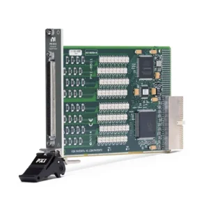
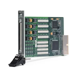
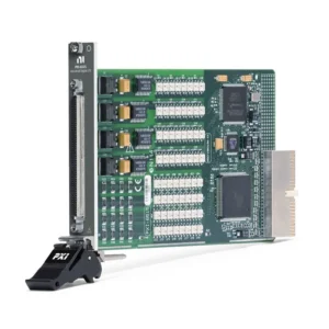
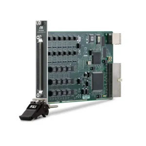
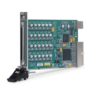
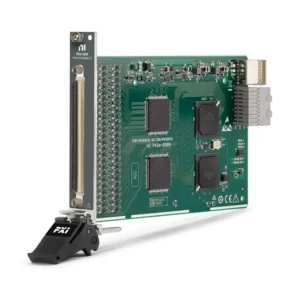

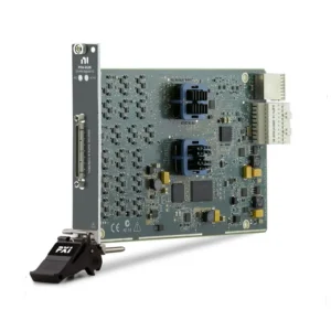
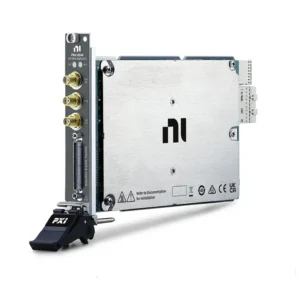
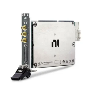
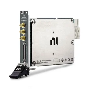
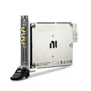
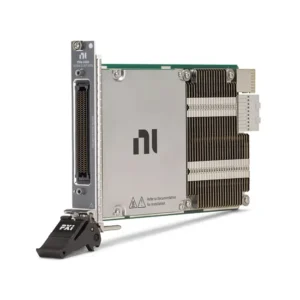
NI PXI Digital Input/Output Modules
NI PXI digital input/output modules provide discrete signal monitoring, device control, parallel waveform acquisition, pattern generation and high-speed digital interface testing within PXI automated test systems. The category ranges from isolated industrial DIO modules for PLC and fixture control to digital waveform, digital pattern, FPGA-based and high-speed serial instruments for electronic validation and semiconductor test.
Engineers should select a module according to logic level, input and output architecture, isolation, channel count, timing rate, data throughput, trigger requirements and software environment. Procurement teams must also confirm the exact model and part number, PXI or PXIe slot compatibility, driver support, cables, terminal blocks, product condition and replacement requirements.
How PXI Digital I/O Works in a Test System
A PXI digital I/O module is installed in a compatible PXI or PXI Express chassis and controlled by an embedded controller or remote computer. It provides the electrical interface between test software and digital signals from the device under test, industrial equipment or test fixture.
Depending on the module architecture, the hardware may read static logic states, switch industrial loads, acquire clocked parallel data, generate stored digital patterns, compare DUT responses or implement custom FPGA-based interfaces. A complete system may combine digital I/O with PXI controllers, chassis and modular instruments for synchronized stimulus, switching, acquisition and analysis.
PXI Digital I/O Product Families
| Product Family | Models in This Category | Technical Function | Selection Priority |
|---|---|---|---|
| Bank-Isolated Industrial DIO | PXI-6511, PXI-6514, PXI-6515 | Industrial-voltage inputs and sourcing or sinking outputs arranged in isolated banks | Input/output direction, sourcing or sinking topology, field voltage and bank reference |
| Channel-Isolated Industrial DIO | PXI-6528, PXI-6529 | Independently referenced isolated channels for industrial monitoring and control | Input/output mix, isolation arrangement, switching current and response time |
| High-Density Static DIO | PXIe-6509 | Software-timed 5 V TTL/CMOS input and output for high-channel-count fixtures | Channel count, current drive, filtering, change detection and safe-state support |
| Streaming Parallel Digital I/O | PXIe-6535, PXIe-6536 | Hardware-clocked digital acquisition and generation with continuous PXIe streaming | Clock rate, aggregate throughput, logic level, direction control and handshaking |
| Digital Waveform Instruments | PXIe-6544, PXIe-6545, PXIe-6547, PXIe-6548 | High-speed digital waveform generation and acquisition using onboard timing and memory | Data rate, voltage range, waveform memory, timing modes, triggering and hardware comparison |
| FPGA-Based LVDS Digital I/O | PXIe-6569 | User-programmable FPGA interface for high-speed LVDS and custom digital protocols | I/O configuration, FPGA size, line rate, memory, connector and development software |
| Digital Pattern Instrument | PXIe-6571 | Per-pin pattern generation, response comparison and semiconductor device testing | Pin count, timing sets, voltage levels, pattern memory and parametric capability |
| High-Speed Serial Instruments | PXIe-6591, PXIe-6592, PXIe-6593 | FPGA-based multi-gigabit serial protocol interfacing and validation | Lane count, transceiver rate, reference clock, connector, protocol IP and FPGA workflow |
These product families are not interchangeable. A module described as digital I/O may be designed for slow industrial control, continuously streamed parallel data, stored digital waveforms, semiconductor pattern testing or multi-gigabit serial links. Selection should begin with the signal architecture rather than channel count alone.
How to Select a PXI Digital I/O Module
1. Define the Digital Interface
Start by determining whether the application requires static control, industrial signal monitoring, synchronous parallel data, digital waveform generation, per-pin semiconductor testing or a serial protocol interface. This decision identifies the correct instrument family before detailed specifications are compared.
2. Confirm Logic Levels and Voltage Limits
Standard digital modules may support TTL, CMOS, LVTTL or configurable low-voltage logic families. Industrial modules may support higher field voltages, while FPGA and serial instruments may use LVDS or multi-gigabit differential signaling.
Check the guaranteed input-low and input-high thresholds, maximum safe input voltage, output-high and output-low levels and voltage tolerance of the DUT. A 5 V TTL input must not be connected directly to a 24 V PLC signal unless a correctly rated isolator or interface circuit is used.
3. Select the Correct Input and Output Architecture
Confirm whether the requirement is input-only, output-only or bidirectional. A bidirectional specification normally means that lines can be configured as inputs or outputs, but it does not automatically mean that direction can change during an active hardware-timed waveform.
Industrial outputs may be sourcing, sinking or isolated solid-state switches. Sourcing outputs are typically paired with sinking loads, while sinking outputs are paired with sourcing loads. Solid-state outputs switch an external circuit and normally do not supply field power independently.
4. Evaluate Isolation Requirements
Bank-isolated modules share a reference across a group of channels and provide good channel density for signals within the same electrical domain. Channel-to-channel isolated modules provide an independent reference for each channel and are more suitable when signals come from different supplies or ground potentials.
Review the working voltage, isolation topology and terminal arrangement—not only the published isolation value. Isolation protects the PXI system from ground differences and common-mode disturbances within specified limits, but it does not make the module immune to overvoltage or incorrect wiring.
5. Determine Static or Hardware-Timed Operation
Software-timed DIO is appropriate for switches, relays, indicators, fixture control and status monitoring where precise edge placement is unnecessary. Hardware-timed DIO is required when samples must follow a defined clock, digital edges must be repeatable or patterns must be acquired and generated continuously.
For hardware-timed modules, compare sample-clock rate, data width, supported timing modes, external clock capability, trigger routing, handshaking and direction-control behavior. The maximum clock rate does not by itself define total system performance.
6. Calculate Data Throughput
High-speed parallel modules can generate substantial data. Approximate payload can be estimated from the number of active bits multiplied by the sample rate and divided by eight. The complete design must also account for acquisition direction, buffering, driver overhead, controller performance and storage speed.
Onboard waveform memory and continuous streaming are different operating modes. A module may generate or acquire a short pattern at its maximum rate from onboard memory while the complete PXIe system cannot sustain the same rate continuously to disk.
7. Check Output Current and Load Behavior
For fixture and industrial control, verify current per channel, total module current, output voltage drop, off-state leakage and power dissipation. Do not assume that a logic output can directly operate a relay, solenoid or actuator.
Inductive loads can generate damaging reverse voltage when switched off. Suitable flyback diodes, snubbers, transient suppressors or interposing relays may be required according to the load and output architecture.
8. Review Startup and Failure States
For modules controlling external equipment, review default power-on states, programmable startup states, watchdog expiration behavior and output states during controller reboot or communication loss. These features support predictable fixture operation but do not replace a safety-rated emergency-stop system.
Digital Waveform, Digital Pattern and High-Speed Serial Instruments
Digital Waveform Instruments
PXIe-6544, PXIe-6545, PXIe-6547 and PXIe-6548 are intended for high-speed parallel digital waveform generation and acquisition. Important parameters include channel count, maximum data rate, supported voltage levels, onboard waveform memory, clocking, triggering and real-time comparison capability.
These instruments are suitable for digital interface validation, memory-device testing, pattern generation and automated functional test. They should not be selected only by maximum frequency because timing flexibility, voltage compatibility and memory architecture can be equally important.
Digital Pattern Instruments
The PXIe-6571 is designed for semiconductor validation and production test workflows that require pin maps, timing sets, voltage levels, pattern bursts and comparison of expected and acquired DUT states. This architecture is different from a general-purpose DIO task built around ports and sample clocks.
Choose a digital pattern instrument when testing integrated circuits or other devices that require repeatable per-pin timing and pattern execution. Standard static DIO remains more practical for fixture control, relays and simple logic monitoring.
FPGA and High-Speed Serial Instruments
The PXIe-6569 and PXIe-6591/6592/6593 families provide user-programmable FPGA resources for custom digital interfaces. The PXIe-6569 targets high-speed LVDS and parallel digital applications, while the PXIe-659x family exposes multi-gigabit transceivers for serial protocol development and validation.
These modules require greater development effort than fixed-function DIO. Selection should include FPGA resource requirements, protocol implementation, transceiver lanes, reference clocks, connector breakout, example designs and the required NI software toolchain.
Software and Driver Compatibility
| Hardware Family | Typical NI Software or Driver | Procurement Consideration |
|---|---|---|
| PXI-651x, PXI-652x, PXIe-6509 and PXIe-653x | NI-DAQmx | Confirm operating-system, LabVIEW and real-time target support |
| PXIe-654x Digital Waveform Instruments | NI-HSDIO | Existing code may depend on a specific driver API and generation |
| PXIe-6571 Digital Pattern Instrument | NI-Digital Pattern Driver and Digital Pattern Editor | Confirm software licensing and compatibility with existing pattern files |
| PXIe-6569 and PXIe-659x FPGA-Based Instruments | FlexRIO software, LabVIEW FPGA and applicable instrument design libraries | Confirm development licenses, supported examples and FPGA compilation workflow |
Driver compatibility is especially important when replacing hardware in a validated production system. A newer module may provide better performance but require changes to the API, channel naming, connector, timing configuration, FPGA code or test limits.
PXI Chassis, Controller and Connectivity
PXI Express modules require compatible PXIe peripheral slots. Classic PXI modules require conventional PXI slots or supported hybrid peripheral slots. Verify the slot map of the exact chassis because the presence of a physical slot does not guarantee electrical compatibility.
High-speed streaming, digital waveform and FPGA-based modules also place greater demands on PXIe backplane bandwidth, controller memory and data storage. Systems using multiple high-throughput modules should be evaluated as a complete data path rather than as independent modules.
Cables and terminal accessories must match the exact front-panel connector and signal standard. Procurement should confirm connector blocks, shielded cables, breakout assemblies, impedance requirements, cable length and whether all channels can be accessed with one accessory set.
Typical Engineering Applications
- Automated production and functional test fixtures
- PLC, sensor, alarm and interlock monitoring
- Relay, indicator and low-current actuator control
- Parallel digital interface and protocol emulation
- Image sensor and display-panel validation
- Semiconductor characterization and production test
- FPGA-based LVDS interface development
- High-speed serial protocol validation
- Automotive ECU and hardware-in-the-loop testing
- Aerospace, defense and laboratory automation
Legacy Module Replacement
A legacy PXI digital I/O module should not be replaced solely by matching channel count. The replacement may use a different bus interface, connector, logic threshold, isolation architecture, output topology, timing engine or driver.
For a direct replacement project, compare:
- PXI or PXI Express slot compatibility
- Connector pinout, cable and terminal block
- Input thresholds and maximum voltage
- Sourcing, sinking or relay output behavior
- Current drive and safe-state behavior
- Hardware timing and trigger routing
- Driver API and operating-system support
- Existing test-code and fixture dependencies
Production systems may require software modification, wiring changes and requalification even when the proposed replacement has higher published performance.
PXI Digital I/O Procurement and RFQ Guide
For accurate model selection and quotation, provide:
- Exact model and part number, if already specified
- Required quantity and preferred product condition
- PXI/PXIe chassis and controller model
- Input, output or bidirectional channel requirement
- Logic family, field voltage and input thresholds
- Sourcing, sinking or isolated switching requirement
- Required isolation topology and working voltage
- Static, hardware-timed, pattern or serial operation
- Clock rate, data rate and trigger requirements
- Cable, terminal block and breakout requirements
- Operating system, NI driver and software version
- Required delivery date and shipping destination
When comparing quotations, confirm whether cables, terminal blocks, calibration documents, testing information and other accessories are included. For pre-owned modules, verify the front connector, PXI backplane connector, device recognition and functional I/O test results.
FAQ
Can a 5 V PXI digital I/O module connect directly to a 24 V PLC?
No. A 5 V TTL/CMOS module should not receive a 24 V industrial signal unless its specifications explicitly allow it. Use a compatible isolated industrial DIO module or an external level-conversion and isolation interface.
What is the difference between PXIe-6509 and PXIe-6536?
PXIe-6509 is a high-density software-timed module for static control and monitoring. PXIe-6536 provides fewer channels but supports hardware-clocked acquisition and generation with continuous high-speed data streaming. The correct choice depends on timing requirements rather than channel count alone.
When should I use a PXI digital pattern instrument?
Use a digital pattern instrument when the application requires per-pin timing, programmable voltage levels, pattern bursts and hardware comparison for semiconductor or device validation. Use standard DIO for basic logic-state acquisition and fixture control.
Can a classic PXI DIO module be installed in a PXIe chassis?
Only when the chassis provides a compatible hybrid peripheral slot and supports the module connector. Check the exact chassis slot map before ordering.
Can a digital output directly drive a relay or solenoid?
Only when the load voltage, current and transient characteristics remain within the output ratings. Many industrial outputs require an external field supply, and inductive loads may require suppression or an interposing relay.
What should be checked when replacing an older DIO module?
Compare the bus interface, connector, pinout, voltage thresholds, isolation, output topology, timing functions, driver API and operating-system support. A module with similar channel count may still require wiring or software changes.
Recommended PXI Digital I/O Modules
Review the PXIe-6509 for high-density static DIO, the PXIe-6536 for continuously streamed parallel digital data, the PXIe-6571 for semiconductor digital pattern testing, or the PXIe-6593 for FPGA-based high-speed serial interface development.
NI PXI Digital Input/Output Modules from PXISOURCE
PXISOURCE supports engineering teams, system integrators and procurement departments sourcing NI PXI digital I/O modules for new systems, production-line expansion, spare inventory and legacy hardware replacement. We can assist with model confirmation, chassis compatibility, software requirements, cables, terminal blocks and project quotations.
Need help selecting an NI PXI digital input/output module? Email sales@pxisource.com or contact PXISOURCE through WhatsApp.