






Showing all 3 results

Filter by price
Filter by brands

- National Instruments
- PXI Systems
- PXI Chassis
- PXI Controller
- PXI Modules
- PXI Semiconductor Test
- PXI FPGA and RIO Modules
- PXI MXI Interfaces
- PXI Programmable Power Supplies & SMU
- PXI Sensor Measurements
- PXI Signal Generators
- PXI Vision
- PXI Data Acquisition
- PXI Oscilloscopes/Digitizers
- PXI Counter/Timers
- PXI RF and Wireless Test
- PXI GPIB, Ethernet and VXI
- PXI Switches
- PXI Digital Multimeters
- PXI Digital Input/Output
- PXI Industrial Communication
- PXI Dynamic Signal Analysis
- PXI Data Streaming
- CompactDAQ Systems
- CompactRIO Systems
- PCI Modules
- USB Devices
- USRP Software Defined Radio Device
- PXI Systems
- keysight
- Tektronix
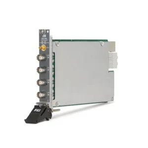
NI PXI Dynamic Signal Analysis Modules
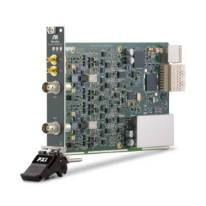
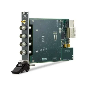
NI PXI Dynamic Signal Analysis modules provide precision acquisition and generation for sound, vibration, acoustic, audio and other time-varying signals. They are designed for applications in which low noise, high dynamic range, simultaneous sampling, phase accuracy and frequency-domain performance are more important than general-purpose multifunction I/O.
PXI DSA modules are commonly used with IEPE accelerometers, measurement microphones, force sensors, dynamic pressure transducers and conditioned voltage signals. Applications include automotive NVH, structural dynamics, modal testing, machine condition monitoring, acoustic characterization, audio testing and aerospace vibration measurement.
What Is PXI Dynamic Signal Analysis?
Dynamic Signal Analysis, commonly abbreviated as DSA, is the measurement and analysis of signals that vary over time. These measurements often focus on amplitude, frequency, phase, distortion, noise and the relationship between multiple synchronized channels.
PXI DSA hardware performs precision signal acquisition or generation, while software handles functions such as FFT analysis, power spectra, frequency response, order analysis, distortion measurement, octave analysis and automated pass/fail testing.
A typical PXI dynamic measurement system includes:
- A compatible PXI Express chassis and controller
- One or more synchronized DSA input or output modules
- Accelerometers, microphones or other dynamic transducers
- Sensor cables, adapters and mounting accessories
- NI-DAQmx and compatible acquisition or analysis software
- Sensor and electronic-channel calibration data
PXI DSA vs General-Purpose DAQ and Digitizers
| Instrument Family | Primary Strength | Typical Signal | Best Fit |
|---|---|---|---|
| PXI Dynamic Signal Analysis | Low-noise synchronized acquisition, high dynamic range and integrated anti-alias filtering | Microphone, accelerometer, audio, vibration and conditioned dynamic voltage | Sound, vibration, NVH, modal and frequency-domain analysis |
| General-Purpose PXI DAQ | Flexible analog, digital, counter and control functions | General voltage, current and control signals | Automated testing, process measurement and mixed-signal I/O |
| PXI Oscilloscope or Digitizer | High analog bandwidth, fast transient capture and deep waveform records | Electronic waveforms, pulses and high-speed transients | Time-domain waveform analysis and high-speed electronic testing |
A higher sample rate does not automatically make an oscilloscope a better sound and vibration instrument. Dynamic measurements may depend more heavily on input noise, phase matching, usable dynamic range, sensor conditioning and anti-alias filtering.
PXI Dynamic Signal Module Types
| Module Type | Function | Typical Use | Important Selection Factors |
|---|---|---|---|
| Dynamic Signal Input | Simultaneously acquires microphone, accelerometer and voltage signals | Vibration, acoustic, NVH and machine-condition measurements | Input channels, IEPE current, range, noise, dynamic range and bandwidth |
| Precision Dynamic Output | Generates low-distortion synchronized waveforms | Audio stimulus, frequency-response testing and device excitation | Output channels, update rate, range, current drive and distortion |
| Dynamic Input and Output | Combines acquisition and waveform generation in one module | Stimulus-response, audio and frequency-response measurements | Input and output rates, channel synchronization, range and software workflow |
NI PXI Dynamic Signal Analysis Module Comparison
| Model | Unique Category | Core Architecture | Best Fit |
|---|---|---|---|
| PXIe-4463 | Precision Dynamic Signal Output | Two 24-bit simultaneous analog outputs, up to 51.2 kS/s, ±10 V output range and 116 dB DSA dynamic range | Low-distortion audio generation, acoustic excitation and precision stimulus applications |
| PXIe-4464 | Four-Channel Dynamic Signal Input | Four simultaneous 24-bit inputs, up to 204.8 kS/s, 119 dB dynamic range, six gain settings, AC/DC coupling, IEPE excitation and TEDS support | Microphone, accelerometer, NVH, structural vibration and machine-diagnostic measurements |
| PXIe-4468 | Integrated Dynamic Signal Input and Output | Two simultaneous 24-bit inputs at up to 250 kS/s and two outputs at up to 200 kS/s, with 121 dB input dynamic range, AC/DC coupling and IEPE conditioning | Audio testing, stimulus-response measurement, frequency-response analysis and laboratory characterization |
The PXIe-4463 is an output-only module and should not be selected for sensor acquisition. The PXIe-4464 provides more input channels, while the PXIe-4468 combines fewer input channels with integrated precision outputs. Select according to the required measurement path rather than model numbering alone.
How to Select a PXI Dynamic Signal Analysis Module
1. Identify the Sensor’s Electrical Output
Obtain the exact sensor model and determine whether it provides an IEPE output, charge output or conditioned voltage. Sensors measuring the same physical quantity can require different signal-conditioning hardware.
IEPE sensors contain integrated electronics and require constant-current excitation. Charge-mode piezoelectric sensors require a charge amplifier or a compatible charge input. A standard IEPE input should not be assumed to support charge-mode sensors directly.
2. Calculate the Required Input and Output Channels
Count all measurement, reference and excitation channels. A modal test may require several response accelerometers plus an instrumented hammer or force-reference channel. An audio test may require microphone inputs and synchronized stimulus outputs.
Include spare channels and future expansion. When multiple modules are required, confirm how their sample clocks, reference clocks and start triggers will be synchronized.
3. Define the Measurement Frequency Range
Determine the highest frequency that must be measured accurately. Then select a sample rate and module bandwidth that provide sufficient passband while allowing the anti-alias filters to operate correctly.
Maximum sample rate and usable measurement bandwidth are not identical. Review the module’s alias-free bandwidth, filter response and attenuation rather than relying only on the Nyquist frequency.
4. Evaluate Dynamic Range and Noise
Dynamic range indicates the usable span between large signals and signals near the measurement noise floor. It is important when a test must capture strong fundamental components together with small harmonics, bearing signatures, resonances or background noise.
ADC resolution alone does not define measurement quality. Input noise, distortion, gain setting, sensor sensitivity, grounding, shielding and environmental interference all influence the usable result.
5. Select the Correct Input Range
Choose the smallest input range that accommodates sensor bias, normal operating signals and expected transient peaks. An unnecessarily large range can reduce effective resolution, while a range that is too small can cause clipping or overload.
The PXIe-4464 and PXIe-4468 provide six gain settings for matching different signal levels. Estimate both typical and maximum amplitudes before configuring the channel.
6. Confirm IEPE Excitation
IEPE accelerometers and microphones require a compatible constant-current supply through the signal cable. Verify the sensor’s required current, compliance voltage, bias level and cable length.
The PXIe-4464 and PXIe-4468 provide software-configurable IEPE conditioning. Disable the excitation when measuring externally powered or standard voltage-output devices unless the sensor documentation requires it.
7. Choose AC or DC Coupling
DC coupling preserves static and dynamic signal components, making it suitable when low-frequency or near-DC behavior must be measured. AC coupling removes the DC component so that dynamic variations can use more of the available input range.
Check the AC-coupled high-pass response when measuring slow structural motion or very low-frequency vibration. AC coupling can attenuate valid low-frequency content.
8. Determine Whether Dynamic Output Is Required
Output channels are useful for audio stimulus, speaker testing, frequency-response measurements, shaker excitation and other stimulus-response applications. The PXIe-4463 provides two dedicated dynamic outputs, while the PXIe-4468 combines two inputs and two outputs.
Verify output amplitude, update rate, current drive, distortion and load impedance. A precision signal output is not necessarily a power amplifier and may require external amplification to drive a shaker, loudspeaker or other high-power load.
9. Review Connector and Cable Requirements
PXI sound and vibration modules may be available with BNC or mini-XLR front connections depending on the part number. The connector option affects the required sensor cables and system wiring but may not change the module’s core measurement function.
Confirm the complete part number, front connector, sensor connector, cable length and required adapters before ordering.
Sensor and Signal-Conditioning Compatibility
| Sensor or Signal | Required Conditioning | Direct Connection Consideration |
|---|---|---|
| IEPE Accelerometer | Constant-current IEPE excitation | Verify excitation current, sensor bias, sensitivity and cable connection |
| IEPE Microphone | IEPE excitation and appropriate acoustic calibration | Confirm microphone sensitivity, sound-pressure range and connector |
| Charge-Mode Piezoelectric Sensor | Charge amplifier or charge-capable input | Do not connect directly as though it were an IEPE sensor |
| Conditioned Voltage Sensor | Compatible voltage range and coupling | IEPE excitation should normally remain disabled |
| Instrumented Impact Hammer | IEPE or charge conditioning according to the hammer output | Preserve synchronization with response accelerometers |
| Tachometer or Speed Reference | Voltage, digital or counter input compatible with the sensor | A separate DAQ or counter module may be required for order tracking |
Simultaneous Sampling and Phase Accuracy
Simultaneous sampling preserves the timing relationship between channels. This is essential when comparing the phase and amplitude of several accelerometers, microphones or force-response channels.
Multiplexed acquisition introduces a time offset between channels because they are converted sequentially. Even a small offset can create phase error at higher frequencies. PXI DSA modules use simultaneous channel architectures suited to modal analysis, beamforming, multi-axis vibration and frequency-response measurements.
Anti-Aliasing Filters and Filter Delay
Frequency components above the usable measurement band can appear incorrectly at lower frequencies after sampling. DSA modules use anti-alias filters that track the selected sample rate and attenuate out-of-band energy before it corrupts the measured spectrum.
Delta-sigma conversion and digital filtering also introduce propagation delay. This normally does not prevent accurate phase comparison between synchronized channels, but the delay should be considered in control loops, absolute event-timing measurements and low-latency stimulus-response systems.
Frequency-Domain Analysis
DSA measurements are frequently evaluated in the frequency domain using a Fast Fourier Transform. Accurate spectral results depend on more than the hardware sample rate. Engineers should define:
- Measurement bandwidth and sampling rate
- Acquisition duration and frequency resolution
- Window function and leakage requirements
- Number and type of averages
- Input range and sensor sensitivity
- Triggering and synchronization
- Required amplitude and phase accuracy
Longer time records provide finer frequency resolution but increase acquisition time and data volume. Select acquisition settings according to the physical phenomenon instead of operating every test at the maximum sample rate.
Sound, Vibration and NVH Applications
Acoustic and Audio Testing
PXI DSA modules can acquire measurement microphones and generate precision audio stimuli for speaker, amplifier, microphone and acoustic-system characterization. Important factors include microphone conditioning, dynamic range, distortion, grounding and acoustic calibration.
Automotive NVH
Noise, vibration and harshness systems measure accelerometers, microphones, force sensors and speed references across vehicles, electric motors, drivetrains, HVAC systems and chassis structures. Simultaneous sampling enables correlation between multiple vibration and acoustic sources.
Structural Dynamics and Modal Analysis
Modal tests use reference excitation and multiple response sensors to identify natural frequencies, damping and mode shapes. Accurate phase relationships are essential because the analysis depends on the relationship between the applied force and structural response.
Machine Condition Monitoring
Vibration spectra can help identify bearing wear, imbalance, misalignment, gear faults, looseness and resonance. Selection should consider the machine speed, expected fault frequencies, sensor mounting, measurement duration and required long-term data storage.
Aerospace and Mechanical Qualification
Aerospace structures and mechanical assemblies may require synchronized vibration, force, acoustic and pressure channels during shaker tests, structural qualification and component validation. Large systems should be designed around total channel count, cabling, synchronization and data throughput.
Software and Analysis Compatibility
NI PXI sound and vibration modules use NI-DAQmx for device configuration, timing, triggering and data acquisition. LabVIEW can be used to build custom automated measurement and analysis applications, while FlexLogger supports compatible logging and test workflows without developing a complete application.
The LabVIEW Sound and Vibration Toolkit adds functions for frequency analysis, fractional-octave analysis, distortion measurement, order analysis, transient analysis and frequency-response measurement.
Before purchasing hardware for an existing system, verify:
- NI-DAQmx version and operating-system support
- LabVIEW or application-development version
- Sound and vibration analysis-toolkit licensing
- Existing channel names, scaling and calibration data
- TDMS or other required data format
- Driver and API compatibility with legacy application code
PXI System Compatibility and Synchronization
The PXIe-4463, PXIe-4464 and PXIe-4468 require compatible PXI Express slots. Review the selected PXI chassis for slot type, cooling, timing resources and available system bandwidth.
Large systems may require multiple DSA modules to share reference clocks and triggers. Starting several software tasks at approximately the same time is not equivalent to hardware synchronization. Define the required phase and timing accuracy before designing the chassis configuration.
The PXI controller must also support the combined channel count, sample rate, analysis workload and data-recording requirement.
Calibration and Measurement Traceability
A complete measurement system includes both the electronic acquisition channel and the sensor. The PXI module, accelerometers, microphones, force sensors and acoustic calibrators may have separate calibration intervals and documentation.
For regulated, aerospace or production applications, define whether the RFQ requires standard calibration, accredited calibration, measurement data, traceability or complete sensor-to-system verification.
TEDS can help transfer compatible sensor identification and sensitivity information, but it does not eliminate the need to verify calibration status, mounting and channel configuration.
Legacy PXI DSA Replacement
Replacing an older PXI-447x, PXI-446x or related DSA module requires more than matching channel count and sample rate. A newer module may use a different chassis bus, connector, input range, filter response, excitation circuit or driver version.
Compare the following before approving a replacement:
- Classic PXI or PXI Express slot compatibility
- Input, output or combined I/O architecture
- Channel count and simultaneous sampling
- Input range, gain and overload behavior
- Sample rate and alias-free bandwidth
- Dynamic range, noise and distortion
- IEPE excitation and TEDS support
- AC/DC coupling and low-frequency response
- Filter delay and trigger behavior
- BNC, mini-XLR or other connector type
- NI-DAQmx and application-software compatibility
- Calibration and historical-data correlation
Validated production and research systems should be requalified after changing the module model because differences in noise, phase, gain and filtering can affect comparison with historical measurements.
PXI Dynamic Signal Analysis RFQ Guide
Provide the following information for accurate module selection and quotation:
- Sensor manufacturer and complete model number
- IEPE, charge or conditioned voltage output
- Sensor sensitivity and expected signal range
- Required input and output channel quantities
- Highest required measurement frequency
- Required sample rate and acquisition duration
- Dynamic range, noise and phase requirements
- AC or DC coupling requirement
- IEPE current and compliance requirements
- BNC, mini-XLR and sensor-cable requirements
- Single-module or synchronized multi-module system
- Existing PXI chassis and controller model
- Operating system, NI-DAQmx and software versions
- Calibration-documentation requirements
- Required quantity and preferred product condition
When comparing quotations, confirm the complete part number and connector version. Also check whether sensor cables, adapters, terminal accessories, calibration documentation and analysis-software licenses are included.
FAQ
What is the difference between PXIe-4463 and PXIe-4464?
The PXIe-4463 is a two-channel precision dynamic output module. The PXIe-4464 is a four-channel dynamic input module with IEPE excitation. One generates test signals, while the other acquires sensor and voltage signals.
What is the difference between PXIe-4464 and PXIe-4468?
The PXIe-4464 provides four analog input channels and no analog outputs. The PXIe-4468 provides two analog inputs and two analog outputs, making it suitable for applications that require both stimulus generation and response measurement.
Can these modules measure IEPE accelerometers directly?
The PXIe-4464 and PXIe-4468 provide integrated IEPE conditioning for compatible accelerometers and microphones. Verify the sensor excitation-current requirement, bias voltage, sensitivity and connector before connection.
Can an IEPE input measure a charge-mode accelerometer?
Not directly. A charge-mode accelerometer normally requires an external charge amplifier or charge-capable measurement front end. IEPE and charge-mode sensors use different conditioning architectures.
Why is simultaneous sampling important?
It preserves the time and phase relationship between channels. This is essential for modal analysis, multi-axis vibration, acoustic arrays, frequency-response measurements and other applications comparing several sensors.
Does a 24-bit ADC guarantee 24-bit measurement accuracy?
No. ADC resolution is only one factor. Input noise, dynamic range, distortion, selected range, sensor sensitivity, grounding and environmental interference determine the practical measurement quality.
Can the PXIe-4463 directly drive a vibration shaker?
Not necessarily. It provides a precision signal output, but a shaker commonly requires a separate power amplifier. Confirm the shaker and amplifier input requirements before designing the excitation path.
Can several DSA modules be synchronized?
Yes, when the modules, chassis timing resources and software configuration support the required clock and trigger routing. The synchronization architecture should be verified for the exact module combination and required phase accuracy.
Related NI Measurement Solutions
Use PXI data acquisition modules for general-purpose voltage and mixed-signal I/O, or review PXI modules when the system also requires digitizers, signal generators, switching, timing or communication hardware.
NI PXI Dynamic Signal Analysis Modules from PXISOURCE
PXISOURCE supports engineers, laboratories, system integrators and procurement teams with PXI DSA module selection, sensor-interface review, connector matching, chassis compatibility and legacy sound and vibration system replacement. Send the sensor models, channel count, frequency range, chassis model and required hardware condition for a technically matched quotation.
Need help selecting an NI PXI Dynamic Signal Analysis module? Email sales@pxisource.com or contact PXISOURCE on WhatsApp.