





Showing all 7 results

Filter by brands

- National Instruments
- PXI Systems
- PXI Chassis
- PXI Controller
- PXI Modules
- PXI Semiconductor Test
- PXI FPGA and RIO Modules
- PXI MXI Interfaces
- PXI Programmable Power Supplies & SMU
- PXI Sensor Measurements
- PXI Signal Generators
- PXI Vision
- PXI Data Acquisition
- PXI Oscilloscopes/Digitizers
- PXI Counter/Timers
- PXI RF and Wireless Test
- PXI GPIB, Ethernet and VXI
- PXI Switches
- PXI Digital Multimeters
- PXI Digital Input/Output
- PXI Industrial Communication
- PXI Dynamic Signal Analysis
- PXI Data Streaming
- CompactDAQ Systems
- CompactRIO Systems
- PCI Modules
- USB Devices
- USRP Software Defined Radio Device
- PXI Systems
- keysight
- Tektronix

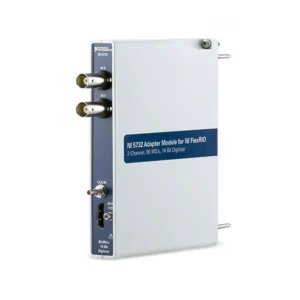
NI C Series High-Speed Digitizer Modules
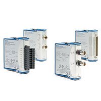
NI C Series high-speed digitizer modules acquire analog waveforms at rates suited to dynamic, transient and time-correlated measurements. They are used in CompactDAQ and CompactRIO systems for voltage waveform capture, machinery analysis, power testing, actuator validation, event monitoring and other applications where a standard low-speed analog input is not sufficient.
Select a digitizer by the complete signal requirement: active channel count, required sample rate, usable bandwidth, input range, input coupling, simultaneous-sampling architecture, trigger behavior, isolation and continuous data-streaming capability. ADC resolution alone does not define the usable measurement performance.
High-Speed Digitizer Measurement Functions
| Measurement Requirement | Digitizer Capability to Review | Typical Application |
|---|---|---|
| Continuous waveform acquisition | Per-channel sample rate, data-transfer path and storage throughput | Long-duration monitoring, process validation and dynamic test logging |
| Transient capture | Trigger mode, pretrigger samples, record length and input protection | Switching events, fault analysis, impact tests and startup measurements |
| Multichannel phase analysis | Simultaneous sampling, channel matching and synchronization support | Vibration, motor, power and structural measurements |
| Frequency-domain analysis | Usable bandwidth, anti-alias filtering, noise and dynamic range | FFT analysis, harmonics, resonance and machinery diagnostics |
| Fast control feedback | Latency, controller architecture and FPGA processing capability | Embedded monitoring, protection systems and real-time control |
| Mixed-signal correlation | Clocking, triggering and timing relationship with other C Series I/O | Electromechanical, automotive and automated test systems |
Key High-Speed Digitizer Considerations
Sample Rate and Usable Bandwidth
Sample rate determines how often the module converts the input signal, while usable bandwidth describes the frequency content that can be measured accurately. Start with the highest frequency of interest, then select a module and sample rate that provide suitable oversampling and anti-alias protection.
A module’s maximum sample rate should not be treated as its guaranteed measurement bandwidth. Input filtering, analog front-end performance, signal source characteristics and analysis requirements all affect the practical result.
Simultaneous Sampling
Simultaneous sampling is important when the timing or phase relationship between channels must be preserved. Examples include three-phase power analysis, vibration measurements, modal testing, motor analysis and correlation between force, pressure and acceleration signals.
Multiplexed analog-input architectures can be suitable for slower signals, but channels are measured at slightly different times. Confirm the acquisition architecture when phase accuracy is part of the test requirement.
Input Range and Signal Integrity
Select the smallest supported input range that accommodates the maximum expected signal, including sensor offset, startup transients and fault conditions. A smaller suitable range generally improves the effective use of the digitizer’s available resolution.
Also review source impedance, common-mode conditions, grounding, cable shielding and expected electrical noise. High-speed acquisition can reveal interference that is not visible in slower measurement systems.
Resolution, Noise and Dynamic Range
ADC resolution indicates the number of digital code levels available, but it does not alone define measurement quality. Input noise, gain error, offset, linearity, filtering and environmental interference affect the usable dynamic range and effective resolution.
For low-level dynamic signals, evaluate sensor sensitivity, cable length, grounding and required input range together. An unsuitable front end can limit performance even when the converter resolution appears high.
Triggering and Record Length
Triggered acquisition is useful when the event of interest occurs at a known condition, such as a switching transition, impact, command signal or fault threshold. Confirm required trigger source, trigger level, edge direction, pretrigger history and post-trigger duration.
Record length determines how much waveform data is retained for each event. Long captures with many active channels can create substantial memory and storage requirements.
How to Select a C Series High-Speed Digitizer Module
1. Define the Signal and Maximum Frequency
Identify the source type and expected signal range. Determine the highest frequency or fastest transient that must be captured, rather than selecting hardware from the nominal physical measurement alone.
A vibration sensor, motor current probe, voltage transducer and strain-gauge conditioner can all produce voltage outputs, but their bandwidth, source impedance, noise level and grounding requirements may be very different.
2. Calculate the Required Sample Rate
Select the sample rate from the required measurement bandwidth, desired waveform detail and analysis method. Provide margin for anti-alias filtering, transient visibility and any post-processing requirements.
For a multichannel system, confirm whether the published rate applies per channel, across all enabled channels or under a specific acquisition configuration.
3. Confirm Channel Count and Sampling Architecture
Count all waveform channels that must be acquired during the same test. Determine whether the application requires simultaneous sampling, synchronized sampling across modules or only independent time-based logging.
Include reference signals, tachometer inputs, trigger channels and auxiliary measurements in the channel plan. These signals are often needed later for correlation and troubleshooting.
4. Match the Input Interface
Verify voltage range, connector type, input coupling, terminal arrangement and supported input topology. Confirm whether the connected sensor requires external excitation, an IEPE supply, a charge amplifier, a bridge conditioner or another dedicated signal-conditioning stage.
Do not connect a sensor directly to a high-speed voltage digitizer unless its electrical output and required conditioning are known to be compatible.
5. Plan Continuous Data Streaming
Long-duration high-speed acquisition requires sufficient system bandwidth and storage performance. Estimate the payload rate using the active channels, sample rate and stored bytes per sample:
Data rate = active channels × sample rate × stored bytes per sample.
Allow additional margin for driver activity, software processing, file format overhead, display updates and other system traffic. Validate the final configuration using the intended record duration and channel configuration.
6. Review Isolation and Grounding
Isolation can help manage ground-potential differences and common-mode conditions, especially in industrial and power-test environments. The required isolation topology depends on the installed equipment, sensor grounding, cable routing and voltage exposure.
Proper shielding and grounding remain important even with isolated hardware. Avoid routing low-level measurement cables beside switching power wiring, motor leads or relay-control cables where practical.
CompactDAQ and CompactRIO Platform Use
CompactDAQ systems are suitable for PC-based waveform logging, portable test and dynamic measurement applications. They can combine high-speed digitizer inputs with digital, temperature, communication and other C Series I/O in one modular system.
CompactRIO systems support embedded applications that may require real-time monitoring, deterministic control or FPGA-based preprocessing. FPGA processing can reduce transferred data, apply custom trigger logic or make time-critical decisions before data reaches the controller.
Verify the exact digitizer module’s compatibility with the selected chassis, controller, operating system, driver version and intended programming environment before ordering.
Software, Synchronization and Data Management
Supported C Series high-speed digitizer modules are commonly configured with NI-DAQmx or the applicable CompactRIO software environment. The software architecture should separate time-critical acquisition from file writing, visualization, analysis and network communication.
Use appropriate clocking and trigger methods when correlating data from multiple modules. For applications requiring phase accuracy, verify the complete synchronization design rather than assuming that all modules in the same chassis share an identical timing relationship.
For high-rate recordings, use buffered acquisition and sequential block writes. Avoid performing frequent small file writes or intensive graphical processing inside the acquisition loop, as these can contribute to buffer overflow or lost data.
A high-speed digitizer is only one part of the measurement chain. The sensor or transducer, signal conditioning, cable assembly, chassis, controller, storage and software must all sustain the required signal bandwidth and data rate.
Typical Applications
- Transient voltage and current capture
- Motor, inverter and power-electronics testing
- Vibration, shock and structural-response measurement
- Automotive and aerospace component validation
- Machine condition monitoring and rotating-equipment analysis
- Actuator, valve and electromechanical response testing
- High-speed sensor waveform recording
- Switching-event and fault analysis
- Laboratory waveform acquisition and FFT analysis
- Embedded real-time monitoring with CompactRIO
C Series High-Speed Digitizer Module Procurement Guide
Provide the following information for an accurate module recommendation:
- Measured signal type, source device and expected voltage range
- Highest frequency of interest or shortest transient to capture
- Required sample rate, record length and continuous acquisition duration
- Number of active analog input channels
- Need for simultaneous sampling and intermodule synchronization
- Required trigger source, trigger condition and pretrigger history
- Sensor output type and any external signal-conditioning requirement
- Grounding, isolation, common-mode and cable-length conditions
- Existing CompactDAQ or CompactRIO chassis and controller model
- Required terminal blocks, cables, connectors and accessories
- Operating system, NI driver version and software environment
- Required quantity, preferred product condition and delivery destination
FAQ
What is the difference between a high-speed digitizer and a standard analog input module?
A high-speed digitizer is selected for faster waveform capture, transient visibility and dynamic-signal analysis. Standard analog input modules are often better suited to slower process, temperature or general monitoring measurements.
Is the highest sample rate the same as usable bandwidth?
No. Sample rate defines how frequently data is converted, while usable bandwidth depends on the analog front end, filtering, signal quality and required measurement accuracy.
Do I need simultaneous sampling?
Simultaneous sampling is recommended when phase or timing relationships between channels matter, such as in power, vibration, force, pressure or structural testing.
Can a high-speed voltage input connect directly to every sensor?
No. Some sensors require excitation, bridge completion, IEPE power, charge conversion or another conditioning stage. Confirm the sensor’s electrical output before connection.
Why can a continuous acquisition stop even when the module sample rate is supported?
Continuous streaming also depends on chassis bandwidth, controller performance, memory buffers, storage throughput, software design and file-writing behavior. The full data path must be validated for the required test duration.
Related NI Modular I/O Solutions
Pair high-speed digitizer modules with CompactDAQ chassis for PC-based dynamic measurement or with CompactRIO controllers for embedded and FPGA-based applications. Explore the complete NI C Series module range for sensor, digital, communication and control I/O.
NI C Series High-Speed Digitizer Modules from PXISOURCE
PXISOURCE helps engineers and procurement teams select compatible NI high-speed digitizer modules, review CompactDAQ and CompactRIO system requirements, match signal-conditioning accessories and source modules for new test systems, spares and legacy replacements.
Need help selecting the right NI C Series high-speed digitizer module? Email sales@pxisource.com or contact PXISOURCE on WhatsApp.