




Showing the single result

Filter by price
Filter by brands

- National Instruments
- PXI Systems
- PXI Chassis
- PXI Controller
- PXI Modules
- PXI Semiconductor Test
- PXI FPGA and RIO Modules
- PXI MXI Interfaces
- PXI Programmable Power Supplies & SMU
- PXI Sensor Measurements
- PXI Signal Generators
- PXI Vision
- PXI Data Acquisition
- PXI Oscilloscopes/Digitizers
- PXI Counter/Timers
- PXI RF and Wireless Test
- PXI GPIB, Ethernet and VXI
- PXI Switches
- PXI Digital Multimeters
- PXI Digital Input/Output
- PXI Industrial Communication
- PXI Dynamic Signal Analysis
- PXI Data Streaming
- CompactDAQ Systems
- CompactRIO Systems
- PCI Modules
- USB Devices
- USRP Software Defined Radio Device
- PXI Systems
- keysight
- Tektronix

NI C Series Dynamic Signal Modules
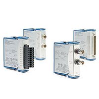
NI C Series Dynamic Signal Modules acquire vibration, acoustic, IEPE accelerometer, microphone, pressure and other time-varying analog signals. They combine low-noise analog input, simultaneous sampling, anti-alias filtering and sensor-specific conditioning for compatible CompactDAQ and CompactRIO systems.
These modules are used when signal bandwidth, phase accuracy, dynamic range and continuous sample timing are more important than the slower scan rates used for temperature or general process monitoring. Select the module from the sensor’s electrical output, required frequency range, active channel count and synchronization requirement.
What Is a C Series Dynamic Signal Module?
A C Series dynamic signal module is a specialized analog input module for continuously changing signals such as acceleration, sound, vibration, dynamic pressure and voltage waveforms. It typically uses simultaneous sampling so that the timing relationship between channels is preserved.
Dynamic signal modules can include functions such as IEPE constant-current excitation, AC or DC coupling, anti-alias filtering, TEDS support on selected models and high-resolution conversion. The appropriate architecture depends on whether the connected sensor is IEPE, voltage output, charge output or externally conditioned.
IEPE and charge-mode piezoelectric sensors are not interchangeable. IEPE sensors contain integrated electronics and require constant-current excitation. Charge-mode sensors require charge-capable conditioning or an external charge amplifier unless the selected input path explicitly supports charge measurement.
Dynamic Signal Input Types
| Input Architecture | Typical Sensor Output | Key Functions to Confirm | Typical Applications |
|---|---|---|---|
| IEPE Dynamic Input | IEPE accelerometer, microphone, force sensor or pressure sensor | Constant-current excitation, AC/DC coupling, input range, TEDS and sensor bias monitoring | Vibration, acoustics, NVH, modal analysis and condition monitoring |
| Dynamic Voltage Input | Voltage output from an external conditioner, amplifier or dynamic transducer | Input range, coupling, common-mode limits, anti-alias filter and input impedance | Voltage waveform measurement, dynamic pressure and externally conditioned sensors |
| High-Channel-Count Dynamic Input | Multiple simultaneous dynamic voltage or sensor channels | Channel density, aggregate data rate, phase matching and storage throughput | Structural testing, machine monitoring and multichannel acoustic arrays |
| High-Bandwidth Dynamic Input | Rapidly changing analog waveforms | Sample rate, usable bandwidth, anti-alias performance and continuous streaming capability | Impact testing, transient capture, rotating machinery and high-frequency vibration |
| Conditioned Dynamic Sensor Input | Voltage from a charge amplifier or external signal conditioner | Conditioner gain, output range, coupling, grounding and calibration scaling | Charge-mode sensors, hydrophones and specialized dynamic transducers |
Representative NI C Series Dynamic Signal Modules
| Model | Unique Category | Key Differentiator | Best Fit |
|---|---|---|---|
| NI-9230 | Dynamic Voltage Input | Dynamic analog voltage acquisition architecture | Conditioned vibration, voltage waveform and general dynamic signal measurement |
| NI-9231 | High-Channel-Count Dynamic Voltage Input | Multiple dynamic voltage channels for synchronized acquisition | Multichannel waveform measurement, structural testing and distributed sensor systems |
| NI-9232 | IEPE Dynamic Signal Input | Integrated conditioning for compatible IEPE dynamic sensors | Accelerometer, microphone and vibration measurements |
| NI-9233 | IEPE Dynamic Signal Input | Dedicated IEPE sensor acquisition architecture | Sound, vibration and dynamic pressure applications |
| NI-9234 | Simultaneous IEPE Dynamic Signal Input | Simultaneous dynamic acquisition with IEPE sensor support | Vibration, acoustic, modal and rotating-machinery analysis |
This table represents common dynamic signal architectures rather than every C Series module that can acquire a changing analog signal. Confirm the exact model, sensor interface, bandwidth, accessory and software support before ordering.
How to Choose a C Series Dynamic Signal Module
1. Identify the Sensor Electrical Interface
Start with the sensor datasheet. Confirm whether the sensor output is IEPE, charge, conditioned voltage, differential voltage or another interface. Also record the nominal sensitivity, maximum output, required excitation, frequency range, connector type, cable type and grounding arrangement.
An accelerometer described only as “piezoelectric” cannot be matched to a module until its output type is known. IEPE sensors need constant-current excitation, while charge-mode sensors normally need an external charge amplifier or a charge-capable input path.
2. Select the Required Bandwidth
Define the highest frequency that must be measured accurately, then select a module whose usable bandwidth and anti-alias filtering support that requirement. Do not select from maximum sample rate alone.
The sample rate must be high enough to support the required measurement bandwidth, but filtering, noise, phase response and storage capability also affect useful dynamic performance. Allow margin for filter transition bands and unexpected higher-frequency content.
3. Determine Channel Count and Simultaneous Sampling
Simultaneous sampling is critical when the phase relationship between channels matters. Examples include modal testing, order analysis, transfer-function measurement, array microphones, multiaxis vibration, force-and-response measurements and rotating-machinery analysis.
For each channel, confirm the required sensor type, range, sensitivity and cable connection. A multichannel system can require different input ranges or sensor configurations even when all channels measure the same physical phenomenon.
4. Check Dynamic Range and Noise
Dynamic range depends on input noise, gain, converter performance, sensor sensitivity, cable noise and the selected input range. A high-resolution converter does not guarantee useful low-level measurement performance if the sensor or installation introduces excessive noise.
Select an input range that accommodates the largest expected signal while keeping small signals above the system noise floor. Include overload conditions such as impacts, startup transients and mechanical shocks.
5. Confirm IEPE Excitation and Coupling
For IEPE sensors, verify the required constant-current excitation, acceptable compliance voltage, sensor bias behavior and whether AC or DC coupling is required. AC coupling removes DC bias and very low-frequency content, while DC coupling is needed when the application must retain those components.
Do not connect a sensor with external power or a non-IEPE output to an IEPE excitation source without verifying the wiring and voltage limits.
6. Review Synchronization and Data Streaming
Dynamic measurements can generate substantial continuous data. Calculate the expected payload rate using:
Data rate = active channels × sample rate × transferred bytes per sample.
Verify chassis bandwidth, host memory, storage speed, network capability and application buffering for the complete acquisition duration. For synchronized systems, also define shared clocks, start triggers, reference timing and timestamp requirements.
IEPE Sensor Measurement
IEPE sensors are widely used for accelerometers, microphones, force transducers and dynamic pressure sensors. The sensor contains integrated electronics and is powered through a constant-current supply on the same cable used for the measurement signal.
Before selecting an IEPE module, confirm:
- Sensor sensitivity and maximum expected output
- Required excitation current and sensor operating limits
- AC or DC coupling requirement
- Frequency range and required low-frequency response
- Cable type, cable length and connector type
- Grounding, shield termination and ground-loop risk
- TEDS support requirements, if applicable
- Input range and overload tolerance
Charge-Mode Sensor Measurement
Charge-mode piezoelectric sensors generate electrical charge rather than an IEPE voltage signal. They are often used in high-temperature, high-shock or specialized measurement environments where integrated IEPE electronics are not appropriate.
A charge-mode sensor normally requires an external charge amplifier or compatible charge conditioning before connection to a C Series voltage input. Confirm the charge amplifier gain, output range, coupling, bandwidth, cable capacitance and calibration scaling as part of the complete measurement path.
Anti-Alias Filtering and Phase Response
Dynamic signal modules use filtering to reduce aliasing from signal content above the usable measurement bandwidth. The filtering architecture can affect frequency response, group delay and phase behavior.
For spectral analysis, transfer-function measurements and phase-sensitive testing, evaluate amplitude response, phase matching and group delay across the required frequency range. A common chassis does not automatically guarantee phase alignment unless the modules and timing configuration support it.
CompactDAQ and CompactRIO Compatibility
C Series dynamic signal modules can be used in compatible CompactDAQ systems and CompactRIO systems. The selected platform determines how modules are configured, synchronized, streamed and integrated with analysis or control software.
CompactDAQ is well suited to PC-based vibration, acoustic and data-logging applications. CompactRIO is appropriate when dynamic signals must be integrated with embedded real-time logic, custom FPGA processing, deterministic triggering or hardware-in-the-loop control.
Software and Analysis Considerations
CompactDAQ dynamic signal applications commonly use NI-DAQmx for channel configuration, timing, triggering and streaming. LabVIEW and FlexLogger can be used for supported acquisition and logging workflows, while advanced analysis applications may require frequency-domain, order-analysis or custom signal-processing functions.
CompactRIO systems can use NI-RIO, LabVIEW Real-Time and LabVIEW FPGA when the design requires embedded deployment or custom processing. Confirm driver, operating-system and software compatibility before selecting a legacy or replacement module.
Typical Applications
- IEPE accelerometer and vibration measurement
- Acoustic and microphone data acquisition
- Noise, vibration and harshness testing
- Rotating-machinery and condition monitoring
- Modal analysis and structural dynamics
- Dynamic pressure, force and impact measurement
- Automotive powertrain and vehicle validation
- Aerospace structural and environmental testing
- Audio, electroacoustic and transducer characterization
- Embedded real-time monitoring and protection systems
C Series Dynamic Signal Module Procurement Guide
Provide the following information for accurate module selection and quotation:
- Sensor manufacturer and complete sensor model
- Sensor output type: IEPE, charge, voltage or externally conditioned output
- Nominal sensitivity, maximum output and required input range
- Required excitation current, coupling mode and TEDS support
- Frequency range, required bandwidth and minimum-frequency response
- Active channel quantity and future expansion requirements
- Required sample rate, simultaneous sampling and phase relationship
- Recording duration, data format and storage requirements
- Grounding, isolation, cable length and connector type
- Existing CompactDAQ chassis or CompactRIO controller model
- Required software, driver and analysis environment
- New or pre-owned hardware preference
FAQ
What is the difference between IEPE and charge-mode sensors?
IEPE sensors contain integrated electronics and require constant-current excitation. Charge-mode sensors generate charge directly and normally require a charge amplifier or charge-capable conditioning before measurement.
Why is simultaneous sampling important for vibration measurement?
Simultaneous sampling preserves the timing and phase relationship between channels. This is important for modal testing, transfer-function measurements, multiaxis vibration, force-and-response measurements and microphone arrays.
Can a general voltage module measure an IEPE accelerometer?
Not directly unless the accelerometer is powered by a suitable external IEPE conditioner and the resulting voltage output is within the module range. A dedicated IEPE dynamic signal module is normally the preferred solution.
Does a higher sample rate always provide better vibration data?
No. The selected sensor, input range, dynamic range, anti-alias filter, noise performance and usable bandwidth must all support the application. A higher sample rate cannot correct poor sensor conditioning or inadequate dynamic range.
Can a dynamic signal module measure a charge-mode piezoelectric sensor?
Only when the selected module and conditioning path explicitly support charge measurement. In many cases, an external charge amplifier is required before connecting the signal to a voltage input.
Can C Series dynamic signal modules be used with CompactRIO?
Yes, when the exact module is supported by the selected CompactRIO controller or chassis. CompactRIO is useful when the application needs embedded deployment, deterministic timing or custom FPGA processing.
Related NI C Series Solutions
Explore the complete NI C Series module range for analog, temperature, digital and communication I/O. Pair dynamic signal modules with a compatible CompactDAQ chassis for PC-based data acquisition, or a CompactRIO controller for embedded real-time and FPGA-based applications.
NI C Series Dynamic Signal Modules from PXISOURCE
PXISOURCE supports engineers, system integrators and procurement teams with IEPE and sensor-interface identification, dynamic signal module selection, CompactDAQ and CompactRIO compatibility review, cable and connector matching, and legacy-module replacement. Send the sensor datasheet, channel count, required bandwidth, sample rate, platform model and preferred hardware condition for a technically matched quotation.
Need help selecting an NI C Series dynamic signal module? Email sales@pxisource.com or contact PXISOURCE on WhatsApp.