






Showing all 8 results

Filter by price
Filter by brands

- National Instruments
- PCI ModulesPCI Modules
- PXI Systems
- PXI Chassis
- PXI Controller
- PXI Modules
- PXI Semiconductor Test
- PXI FPGA and RIO Modules
- PXI MXI Interfaces
- PXI Programmable Power Supplies & SMU
- PXI Sensor Measurements
- PXI Signal Generators
- PXI Vision
- PXI Data Acquisition
- PXI Oscilloscopes/Digitizers
- PXI Counter/Timers
- PXI RF and Wireless Test
- PXI GPIB, Ethernet and VXI
- PXI Switches
- PXI Digital Multimeters
- PXI Digital Input/Output
- PXI Industrial Communication
- PXI Dynamic Signal Analysis
- PXI Data Streaming
- CompactDAQ Systems
- CompactRIO Systems
- PCI Modules
- USB Devices
- USRP Software Defined Radio Device
- keysight
- Tektronix


In stock
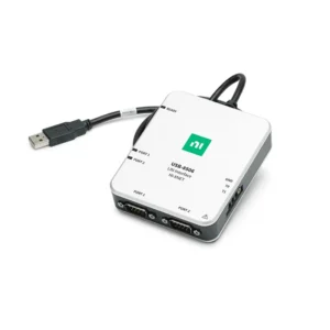
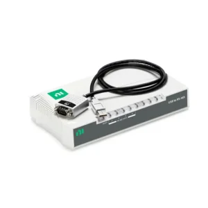
NI PCI Industrial Communication Interfaces
NI PCI and PCI Express industrial communication interfaces connect desktop or industrial computers to vehicle networks, serial equipment, industrial controllers and automated test systems. They support monitoring, logging, simulation, diagnostics and software-controlled communication through protocols such as CAN, CAN FD, LIN, FlexRay, RS-232, RS-422 and RS-485, depending on the selected device.
Select an interface by the required communication protocol and electrical physical layer, then confirm host-computer slot compatibility, port count, data rate, isolation, termination, timestamping, connector accessories and software-driver support.
PCI Industrial Communication Interface Types
| Interface Type | Typical Standard | Primary Use | Key Selection Considerations |
|---|---|---|---|
| CAN and CAN FD | Controller Area Network | Vehicle networks, battery systems, industrial machinery and ECU testing | Classic CAN or CAN FD, channel count, bit rate, termination and isolation |
| LIN | Local Interconnect Network | Automotive body-electronics monitoring and simulation | Master or slave role, schedules, transceiver compatibility and database support |
| FlexRay | Deterministic automotive network | Vehicle development, validation and network simulation | Channel configuration, timing, topology and supported software |
| Serial Communication | RS-232, RS-422 or RS-485 | Industrial instruments, PLCs, drives, sensors and legacy equipment | Electrical standard, port count, duplex mode, isolation and connector pinout |
| Industrial Ethernet and Fieldbus | Supported Ethernet-based or application-specific industrial protocols | Controller integration, distributed automation and equipment communication | Exact protocol, network architecture, driver and application compatibility |
| Instrument Communication | Supported instrument-bus or legacy interfaces | Automated instrument control and laboratory systems | Instrument protocol, cable type, software API and legacy support |
PCI Compared with PCI Express Communication Interfaces
| Interface | Computer Bus | Best Fit | Compatibility Requirement |
|---|---|---|---|
| PCI | Legacy shared parallel bus | Existing industrial computers and established test systems | Compatible PCI slot, voltage keying, operating system and driver |
| PCI Express | Point-to-point serial PCIe connection | Current workstations and new communication-test systems | Compatible PCIe slot, bracket size, lane allocation and driver support |
PCI and PCI Express use different physical and electrical interfaces. A PCI communication card cannot be installed in a PCIe slot, and a PCIe card cannot be installed in a legacy PCI slot.
How to Select a PCI Industrial Communication Interface
1. Identify the Required Protocol
Start with the connected device, vehicle or industrial equipment documentation. Determine whether the application requires CAN, CAN FD, LIN, FlexRay, RS-232, RS-422, RS-485, industrial Ethernet or another supported interface.
A connector shape does not identify the communication standard. Confirm the protocol, transceiver, signal voltage, pinout, bus topology and communication role before selecting hardware.
2. Verify the Computer Expansion Slot
Inspect the host computer or industrial PC and confirm whether it provides PCI or PCI Express expansion slots. For PCIe cards, review the available slot size, chipset allocation, mechanical clearance and full-height or low-profile bracket requirement.
Newer workstations may provide only PCIe, while established industrial systems can still use legacy PCI. Motherboard compatibility should be confirmed before replacing the communication interface.
3. Determine Port and Channel Count
Count the number of independent networks or serial ports required. Separate CAN buses, isolated vehicle subsystems or independent serial devices can each require a dedicated channel.
For RS-485 systems, determine whether the network uses two-wire or four-wire wiring, half-duplex or full-duplex communication, and one or multiple devices on the bus.
4. Confirm Data Rate and Traffic Load
Record the required baud rate, message frequency, frame type and expected bus loading. The interface must sustain the complete receive, transmit, timestamping and logging workload.
CAN FD applications should verify arbitration-phase and data-phase requirements. High message rates and several simultaneous channels can increase host processing and storage demands.
5. Evaluate Isolation and Grounding
Isolation can help protect the computer from ground-potential differences, electrical noise and transients. It is particularly important when connecting to machinery, vehicle electrical systems, long cables or separately powered equipment.
Isolation does not eliminate the need for correct grounding, shielding and cable routing. Review the complete electrical installation before connecting the communication card.
6. Plan Termination and Cabling
CAN networks normally require termination at both physical ends of the bus. Incorrect termination, excessive stub length or unsuitable cable can create intermittent communication failures.
Serial and industrial network systems also require appropriate cable type, connector pinout and shielding. Confirm the required breakout cable, terminal accessory, adapter and external termination before ordering.
7. Define Timestamping and Synchronization
Vehicle and industrial network logs often need timestamps so messages can be correlated with analog measurements, digital events, commands or faults. Define the required timing accuracy before selecting hardware.
Applications using several communication cards or additional DAQ hardware should verify the available clock, trigger and synchronization methods. A shared host computer does not automatically provide hardware-aligned timestamps.
CAN, CAN FD, LIN and FlexRay Considerations
CAN and CAN FD
CAN is widely used in automotive electronics, battery systems, industrial machinery and mobile equipment. CAN FD extends classic CAN with larger payload capability and, in supported networks, a faster data phase.
Determine whether the application is passive monitoring, message logging, active transmission, ECU simulation or hardware-in-the-loop testing. An active test interface can have different configuration and bus-access requirements from a receive-only logger.
LIN
LIN is used for lower-cost automotive subnetworks and body-electronics functions. Selection should account for master or slave behavior, schedule timing, signal databases and the intended simulation or monitoring role.
FlexRay
FlexRay supports deterministic communication in selected vehicle systems. Verify network topology, channel configuration, timing, synchronization and the required software environment.
A communication interface provides electrical and software access to the bus. It does not automatically include vehicle databases, ECU definitions, diagnostic files, simulation models or the correct wiring harness.
RS-232, RS-422 and RS-485 Considerations
RS-232 is generally used for point-to-point communication over shorter distances. RS-422 and RS-485 use differential signaling and are commonly selected for longer cables or electrically noisy industrial environments.
RS-485 can support multidrop networks when the wiring, termination and transmit-direction control are configured correctly. Confirm baud rate, data bits, parity, stop bits, flow control and the connected device’s command protocol.
RS-232, RS-422 and RS-485 are not electrically interchangeable. Use the interface designed for the connected equipment or a suitable external converter.
Software and Driver Compatibility
Supported NI automotive network interfaces commonly use NI-XNET for CAN, CAN FD, LIN and FlexRay communication. Serial interfaces typically use the applicable NI serial or VISA software environment. Other industrial protocols can require their own driver or toolkit.
Before purchasing or replacing a communication interface, confirm:
- Operating-system support
- NI driver and toolkit version
- LabVIEW, TestStand or application compatibility
- Database format and signal-description files
- Application programming interface
- Firmware and hardware revision support
Legacy PCI Communication Interface Replacement
Replacing a legacy PCI card with a PCIe interface requires more than matching the protocol and channel count. The replacement can use different connectors, cables, isolation, transceivers, timestamping methods or software APIs.
Compare the following before approving a replacement:
- PCI or PCIe host-slot compatibility
- Supported communication protocol and physical layer
- Port quantity, isolation and termination
- Connector and cable pinout
- Supported baud rates and frame formats
- Timestamping and synchronization behavior
- Operating-system, driver and application compatibility
- Database and configuration-file support
Requalify communication, message timing, error handling and long-duration logging with the intended equipment before production use.
Typical Applications
- Automotive CAN, CAN FD, LIN and FlexRay logging
- ECU development, validation and diagnostics
- Battery-management-system communication testing
- Hardware-in-the-loop network simulation
- Industrial PLC, drive and controller integration
- Serial instrument and legacy-equipment control
- Production-line communication monitoring
- Automated instrument-control systems
- Vehicle and machinery fault investigation
- Combined network and sensor-data acquisition
PCI Industrial Communication Interface Procurement Guide
Provide the following information for accurate interface selection and quotation:
- Required protocol and electrical physical layer
- Connected device, ECU, instrument or equipment model
- Required PCI or PCI Express computer interface
- Host computer model and available expansion slots
- Required number of independent ports or bus channels
- Required baud rate, message rate and expected bus loading
- Monitoring, logging, simulation, diagnostics or control requirement
- Isolation, grounding and termination requirements
- Required cables, breakout accessories, adapters and harnesses
- Timestamping and synchronization requirements
- Operating system, NI driver and application-software versions
- Required quantity, preferred product condition and delivery destination
FAQ
What is the difference between PCI and PCIe communication cards?
PCI uses a legacy parallel computer bus, while PCI Express uses point-to-point serial links. The slots and connectors are different and are not directly interchangeable.
What is the difference between CAN and CAN FD?
CAN FD extends classic CAN with larger payloads and, in supported networks, a faster data phase. The interface, connected nodes and software must all support CAN FD.
Do CAN interfaces require termination?
A CAN network normally requires termination at its two physical ends. Verify the existing bus topology before adding or enabling termination.
Can an RS-485 device connect to an RS-232 interface?
No. They use different electrical signaling methods. Select the correct interface or use an appropriate external converter.
Can communication data be synchronized with DAQ measurements?
It can be correlated, but achievable timing accuracy depends on the communication hardware, timestamping method, DAQ device and available synchronization architecture.
Related NI Communication and Test Platforms
Explore NI PCI and USB devices for PC-based communication hardware. Use CompactDAQ systems for modular communication and sensor acquisition, CompactRIO systems for embedded real-time communication, or NI PXI systems for high-channel-count automated test.
NI PCI Industrial Communication Interfaces from PXISOURCE
PXISOURCE supports engineers and procurement teams with PCI and PCIe communication-interface selection, protocol and host compatibility review, accessory matching and sourcing for new systems, spare inventory and legacy replacements.
Need help selecting the right NI PCI industrial communication interface? Email sales@pxisource.com or contact PXISOURCE on WhatsApp.