




Showing all 4 results

Filter by price
Filter by brands

- National Instruments
- PXI Systems
- PXI Chassis
- PXI Controller
- PXI Modules
- PXI Semiconductor Test
- PXI FPGA and RIO Modules
- PXI MXI Interfaces
- PXI Programmable Power Supplies & SMU
- PXI Sensor Measurements
- PXI Signal Generators
- PXI Vision
- PXI Data Acquisition
- PXI Oscilloscopes/Digitizers
- PXI Counter/Timers
- PXI RF and Wireless Test
- PXI GPIB, Ethernet and VXI
- PXI Switches
- PXI Digital Multimeters
- PXI Digital Input/Output
- PXI Industrial Communication
- PXI Dynamic Signal Analysis
- PXI Data Streaming
- CompactDAQ Systems
- CompactRIO Systems
- PCI Modules
- USB Devices
- USRP Software Defined Radio Device
- PXI Systems
- keysight
- Tektronix
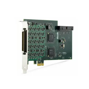


NI PXI Counter/Timer Modules
NI PXI Counter/Timer modules are hardware-timed digital instruments used to count events, measure frequency and period, acquire encoder position, measure pulse width and generate programmable pulses or pulse trains. They are designed for automated test systems in which timing accuracy, repeatability and multiple simultaneous counter operations are more important than general analog acquisition.
Dedicated PXI Counter/Timer modules are commonly used in motor and encoder testing, industrial automation, automotive validation, aerospace systems, manufacturing equipment, electronic functional test and scientific measurement. They integrate with PXI chassis timing resources and NI-DAQmx software for synchronized measurement and programmable control.
Selecting the correct module requires evaluation of counter quantity, input voltage, maximum frequency, timebase accuracy, isolation, digital filtering, encoder configuration, buffered acquisition, pulse-generation requirements, connector accessories and PXI or PXI Express compatibility.
What Does a PXI Counter/Timer Do?
A counter/timer detects digital signal transitions and uses a hardware timing reference to determine how many events occurred or how much time passed between selected edges. Because edge detection and timing take place in dedicated hardware, the measurement does not depend on the operating system responding to every individual event.
Typical PXI Counter/Timer operations include:
- Event and pulse counting
- Frequency measurement
- Period and semi-period measurement
- High- and low-pulse-width measurement
- Two-edge separation measurement
- Quadrature encoder position measurement
- Angular and linear position tracking
- Single-pulse generation
- Finite and continuous pulse-train generation
- Retriggerable pulse generation
- PWM measurement and generation
- Buffered event and position acquisition
A PXI Counter/Timer is installed in a compatible PXI or PXIe chassis and controlled by an embedded PXI controller or a supported remote computer.
PXI Counter/Timer Measurement Types
| Operation | What It Measures or Generates | Typical Applications |
|---|---|---|
| Event Counting | Number of valid digital edges or pulses | Production counts, machine cycles, detector events and sensor pulses |
| Frequency Measurement | Number of repeating events per unit of time | Clocks, oscillators, tachometers, flow meters and rotational speed |
| Period Measurement | Elapsed time between corresponding signal edges | Low-frequency signals, speed measurement and precision timing |
| Pulse-Width Measurement | Duration of the high or low portion of a pulse | PWM signals, injector timing, control pulses and digital validation |
| Two-Edge Separation | Time between selected events on two signal paths | Propagation delay, response time and trigger-latency measurement |
| Encoder Position | Position and direction from quadrature encoder signals | Motors, actuators, dynamometers, motion stages and machine tools |
| Pulse Generation | Single, finite, continuous or retriggerable digital pulses | Triggers, clocks, sensor simulation and test stimulus |
| Buffered Acquisition | A time history of count, period, frequency or position values | Continuous monitoring and correlation with analog measurements |
Representative NI PXI Counter/Timer Models
| Model | Unique Category | Core Architecture | Best Fit |
|---|---|---|---|
| PXIe-6612 | General-Purpose PXIe Counter/Timer | Eight 32-bit counter/timers, 40 bidirectional 5 V TTL digital lines and frequency measurement up to 80 MHz | General event counting, encoder acquisition, frequency measurement and pulse generation |
| PXIe-6614 | Precision-Reference PXIe Counter/Timer | Eight 32-bit counter/timers, 40 bidirectional 5 V TTL digital lines, frequency measurement up to 80 MHz and onboard high-precision OCXO | Long-duration timing, precision frequency measurement and applications requiring improved reference stability |
| PXI-6624 | Isolated Industrial PXI Counter/Timer | Eight counter/timers, 48 V channel-to-channel isolated I/O, 26 isolated digital inputs and eight isolated sinking outputs | Industrial sensors, machinery, automotive equipment and higher-voltage field signals |
The PXIe-6612 and PXIe-6614 use 5 V TTL-compatible digital I/O and are intended for general high-speed timing applications. The PXI-6624 uses an isolated industrial architecture for signals up to 48 VDC. These modules are not direct substitutes even though each provides eight counter/timers.
PXIe-6612 vs PXIe-6614 vs PXI-6624
| Selection Factor | PXIe-6612 | PXIe-6614 | PXI-6624 |
|---|---|---|---|
| Platform | PXI Express | PXI Express | PXI Hybrid |
| Counter/Timers | 8 | 8 | 8 |
| Counter Resolution | 32-bit | 32-bit | 32-bit |
| Digital Signal Architecture | 5 V TTL/CMOS compatible | 5 V TTL/CMOS compatible | Isolated industrial I/O up to 48 VDC |
| Digital I/O | 40 bidirectional lines | 40 bidirectional lines | 26 isolated inputs and eight isolated sinking outputs |
| Maximum Listed Measurement Frequency | 80 MHz | 80 MHz | 400 kHz isolated I/O measurement |
| High-Precision Oscillator | No | Yes, onboard OCXO | No |
| Primary Selection Reason | General high-speed timing | Improved long-term timing accuracy | Isolation and industrial voltage compatibility |
How to Select a PXI Counter/Timer Module
1. Identify the Required Counter Operation
Begin by defining whether the system must count events, measure frequency, measure pulse width, acquire encoder position, generate pulse trains or perform several operations simultaneously. The number of connected sensors does not always equal the number of counter resources required.
For example, a test system may use one counter to measure encoder position, another to provide a sample clock and a third to generate a stimulus pulse. Count every simultaneous measurement and generation task before selecting the module.
2. Determine the Number of Counters
NI PXIe-6612, PXIe-6614 and PXI-6624 each provide eight counter/timer resources. This is useful for systems requiring multiple encoders, frequency inputs or independently generated pulse trains.
If an application needs only one or two timing operations together with analog measurement, a multifunction PXI data acquisition module with integrated counters may be sufficient. A dedicated counter/timer becomes more valuable when timing functions are the primary requirement.
3. Match the Electrical Signal Level
Determine the signal’s logic-high and logic-low voltages, maximum voltage, source type, ground reference, output impedance, rise and fall times and maximum frequency. TTL counter hardware should not be connected directly to an industrial 24 V or 48 V signal.
PXIe-6612 and PXIe-6614 are intended for 5 V TTL/CMOS-compatible digital signals. PXI-6624 is designed for isolated industrial signals up to 48 VDC. Sensors with differential, open-collector, analog or other output types may require additional signal conditioning.
4. Define the Frequency Range
Provide both the minimum and maximum expected frequency. The best counter measurement method can change across the frequency range.
Direct frequency measurement is efficient for faster repetitive signals. Period measurement can provide better resolution at lower frequencies because it measures the elapsed time between individual edges rather than counting a limited number of events during a fixed gate interval.
Maximum supported frequency also depends on signal amplitude, transition time, filtering configuration and the selected input architecture. Industrial isolation can reduce the maximum usable input frequency compared with direct TTL timing inputs.
5. Compare Timing Resolution and Timebase Accuracy
Timing resolution describes the smallest interval the counter hardware can distinguish. Timebase accuracy describes how closely the reference clock matches its nominal frequency. These specifications are related but not interchangeable.
A counter can provide fine short-term resolution while still accumulating error during a long-duration measurement if its reference clock drifts. Applications such as oscillator characterization, calibration, long-duration period measurement and precision frequency testing should include timebase uncertainty in the accuracy calculation.
The PXIe-6614 includes an oven-controlled crystal oscillator, or OCXO, to improve reference stability. The PXIe-6612 is appropriate when the standard counter timebase already meets the application requirement.
6. Review Encoder Requirements
Quadrature encoders commonly provide A and B signals with a phase relationship that indicates both position and direction. An optional Z or index signal provides a reference position.
For encoder applications, specify:
- Incremental or other encoder type
- Single-ended or differential signal format
- Encoder supply and output voltage
- Pulses per revolution or distance
- X1, X2 or X4 decoding requirement
- Maximum rotational or linear speed
- Use of the index channel
- Required position and direction information
- Continuous buffering or sample-clock requirements
The maximum edge rate should be calculated from encoder resolution, decoding mode and maximum speed. Selecting X4 decoding increases position resolution but also increases the counter input edge rate.
7. Evaluate Digital Filtering
Mechanical switches, encoders, proximity sensors and long field cables can produce contact bounce or electrical noise. Without filtering, unwanted transitions may be counted as valid events.
Programmable digital filters can reject pulses shorter than a defined interval. The filter must be short enough to preserve the fastest valid signal. An excessive filter duration can remove real events and produce incorrect frequency or position results.
8. Determine Pulse-Generation Requirements
Counter outputs can generate single pulses, finite pulse trains, continuous clocks, retriggerable pulses and programmable frequency or duty-cycle signals. These outputs can provide triggers, clocks, simulated sensor signals or digital test stimulus.
Counter outputs are timing signals rather than motor or actuator power outputs. Stepper motors, solenoids, relays and other power loads normally require an external driver or interface circuit.
9. Plan Buffered Acquisition and DMA
A software-requested counter reading returns the current value at the time of the call. Buffered acquisition stores a sequence of counter values using a hardware sample clock, allowing position, count, period or frequency to be analyzed over time.
Buffered measurements are useful when counter data must be synchronized with voltage, current, temperature or other measurements. Confirm the number of simultaneous buffered tasks, sampling rate, acquisition duration and available DMA resources.
10. Check Isolation and Grounding
Isolation is important when field signals use different electrical references or when ground-potential differences could cause measurement errors. The PXI-6624 provides channel-to-channel isolated industrial I/O, while PXIe-6612 and PXIe-6614 use a general TTL timing architecture.
Isolation does not eliminate the need to follow input-voltage, measurement-category and wiring limits. Review the device manual before connecting industrial equipment or externally powered sensors.
Dedicated Counter/Timer vs Multifunction PXI DAQ
| Requirement | Dedicated Counter/Timer | Multifunction PXI DAQ |
|---|---|---|
| Primary Function | Counting, timing, encoder acquisition and pulse generation | Analog input, analog output and general-purpose acquisition |
| Counter Quantity | Typically optimized for multiple counters | Usually includes fewer counters |
| Analog Measurement | Not the primary function | Primary capability |
| Encoder Applications | Suitable for multiple encoders or dedicated motion measurement | Suitable for smaller systems with limited encoder requirements |
| Precision Reference | Available on specialized models such as PXIe-6614 | Depends on the selected DAQ model |
| Industrial Isolation | Available with PXI-6624 | Depends on the DAQ architecture |
PXI Counter/Timer vs PXI Synchronization Module
A Counter/Timer measures or generates timed digital events. A synchronization module primarily distributes reference clocks and triggers between instruments or chassis.
Choose a Counter/Timer for frequency measurement, encoder position, event counting, pulse-width measurement or pulse generation. Choose a PXI synchronization module when the main requirement is clock distribution, low-skew triggering or multichassis synchronization.
Cables, Terminal Blocks and Connectivity
Counter/Timer modules use high-density front-panel connectors and normally require a compatible cable and terminal accessory. The correct accessory depends on the model, field wiring, required shielding and preferred connection method.
| Module Family | Connectivity Considerations | Common Procurement Risk |
|---|---|---|
| PXIe-6612 / PXIe-6614 | 68-pin cable and a compatible BNC, shielded or general-purpose terminal block | Ordering the module without the required cable or breakout accessory |
| PXI-6624 | 100-pin cable and terminal accessory compatible with isolated field wiring | Assuming that accessories for the 68-pin 66xx modules are interchangeable |
| Encoder Systems | A/B/Z wiring, shield, supply, grounding and single-ended or differential interface | Encoder electrical output does not match the counter input |
| Industrial Sensors | Voltage, source or sinking output, isolation and reference connections | Connecting 24 V or 48 V signals directly to a 5 V TTL input |
Confirm cable length and pinout for replacement projects. Even modules with similar counter functions may use different front connectors, terminal blocks and signal assignments.
Software and System Compatibility
NI PXI Counter/Timer modules use NI-DAQmx for task configuration, timing, triggering, digital filtering, buffered acquisition and pulse generation. NI Measurement & Automation Explorer can be used to confirm device recognition, inspect available channels and perform basic hardware checks.
Counter tasks can be integrated with LabVIEW, TestStand and supported C/C++ or .NET environments. Verify the NI-DAQmx version, operating system and development environment before purchasing hardware for an existing system.
For mixed-module applications, confirm how sample clocks, start triggers, reference clocks and PXI trigger lines will be routed. Installing instruments in the same chassis does not automatically synchronize their measurements.
Typical Engineering Applications
- Motor speed, direction and position measurement
- Quadrature encoder and tachometer acquisition
- Automotive wheel-speed and PWM signal testing
- Injector and actuator pulse-width measurement
- Industrial production and machine-cycle counting
- Flow-meter and pulse-output sensor measurement
- Clock, oscillator and digital-frequency verification
- Propagation-delay and response-time measurement
- Trigger, clock and pulse-train generation
- Manufacturing functional test
- Aerospace timing and electromechanical validation
- Scientific event counting and laboratory automation
Legacy PXI Counter/Timer Replacement
Legacy systems may use PXI-6601, PXI-6602, PXI-6608 or other earlier counter/timer devices. A newer PXIe module is not necessarily a direct replacement because the bus interface, front connector, timebase, counter routing, filters, DMA resources and software behavior may differ.
Compare the following before approving a replacement:
- PXI, hybrid PXI or PXI Express slot compatibility
- Number and resolution of counters
- Input and output voltage levels
- Maximum supported frequency
- Timebase accuracy and reference-clock behavior
- Encoder and index-channel requirements
- Digital filter configuration
- Buffered acquisition and DMA resources
- Front-panel connector and cable pinout
- PXI trigger routing
- NI-DAQmx and operating-system support
- Application-code and test-system requalification
For validated production equipment, obtaining the original module may avoid rewiring, software modifications and timing requalification. For new systems, PXIe-6612 or PXIe-6614 may provide a more suitable current PXI Express architecture.
PXI Counter/Timer Procurement and RFQ Guide
Provide the following information for accurate selection and quotation:
- Required module model and part number, if known
- Event counting, frequency, period, pulse-width or encoder requirement
- Number of simultaneous counter operations
- Input and output voltage levels
- Minimum and maximum signal frequency
- Required timing and frequency accuracy
- Encoder type, resolution and maximum speed
- X1, X2 or X4 decoding requirement
- Pulse or PWM generation requirements
- Buffered acquisition and sample-rate requirements
- Isolation and grounding requirements
- Existing PXI chassis and controller models
- Required cables, terminal blocks and accessories
- NI-DAQmx and operating-system versions
- New or pre-owned hardware preference
- Required quantity, delivery date and destination
FAQ
What is the difference between PXIe-6612 and PXIe-6614?
Both provide eight 32-bit counters, 40 bidirectional 5 V TTL digital lines and frequency measurement up to 80 MHz. PXIe-6614 adds a high-precision onboard OCXO for applications requiring improved long-term timing and frequency accuracy.
When should I choose PXI-6624?
Choose PXI-6624 when the application requires channel-to-channel isolation or direct compatibility with industrial signals up to 48 VDC. PXIe-6612 and PXIe-6614 are better suited to general high-speed 5 V TTL timing signals.
Can a PXI Counter/Timer measure a quadrature encoder?
Yes. Compatible counter modules can decode A and B signals to determine position and direction and can use an index signal where supported by the configuration. Confirm signal voltage, encoder resolution and maximum edge rate.
Can a Counter/Timer generate PWM signals?
Yes. Hardware counters can generate pulse trains with programmable frequency and duty cycle. An external driver is required when the load needs more voltage or current than the counter output can provide.
Do I need a dedicated Counter/Timer if my DAQ module has counters?
Not always. Integrated DAQ counters can be sufficient for a small number of basic operations. Use a dedicated module when more counters, precision timing, additional buffered tasks or industrial isolation are required.
Is PCIe-6612 a PXI module?
No. PCIe-6612 installs in a desktop or industrial computer with a PCI Express slot. PXIe-6612 provides closely related counter/timer functionality for a PXI Express chassis.
Can PXIe Counter/Timer modules directly accept 24 V industrial signals?
Not when the module uses 5 V TTL inputs. Use an isolated industrial module such as PXI-6624 or appropriate external signal conditioning after verifying all voltage and frequency limits.
Recommended NI PXI Counter/Timer Modules
Select PXIe-6612 for general-purpose PXI Express event counting, encoder and pulse applications; choose the PXIe-6614 when high-precision reference timing is required; or use the PXI-6624 for isolated industrial signals up to 48 VDC.
Related NI Measurement Solutions
Use PXI data acquisition modules when counter measurements must be combined with analog voltage or sensor acquisition. Review PXI modules for additional digital I/O, synchronization and automated test hardware.
NI PXI Counter/Timer Modules from PXISOURCE
PXISOURCE supports engineers, system integrators and procurement teams with counter/timer model selection, PXI chassis compatibility review, encoder interface planning, cable and terminal-block matching, industrial signal evaluation and legacy module replacement.
Send the signal voltage, frequency range, counter quantity, encoder specification, chassis model and timing-accuracy requirement for a technically matched quotation.
Need help selecting an NI PXI Counter/Timer module? Email sales@pxisource.com or contact PXISOURCE through WhatsApp.