






Showing all 4 results

Filter by price
Filter by brands

- National Instruments
- PCI ModulesPCI Modules
- PXI Systems
- PXI Chassis
- PXI Controller
- PXI Modules
- PXI Semiconductor Test
- PXI FPGA and RIO Modules
- PXI MXI Interfaces
- PXI Programmable Power Supplies & SMU
- PXI Sensor Measurements
- PXI Signal Generators
- PXI Vision
- PXI Data Acquisition
- PXI Oscilloscopes/Digitizers
- PXI Counter/Timers
- PXI RF and Wireless Test
- PXI GPIB, Ethernet and VXI
- PXI Switches
- PXI Digital Multimeters
- PXI Digital Input/Output
- PXI Industrial Communication
- PXI Dynamic Signal Analysis
- PXI Data Streaming
- CompactDAQ Systems
- CompactRIO Systems
- PCI Modules
- USB Devices
- USRP Software Defined Radio Device
- keysight
- Tektronix

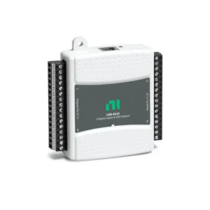
NI PCI Digital I/O Devices
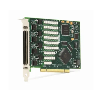
NI PCI and PCI Express digital I/O devices install inside a desktop, workstation or industrial computer to provide digital monitoring, control and automated test functions. They are used to read switches, sensors and machine status; control logic signals and external drivers; and acquire or generate supported hardware-timed digital patterns.
Select a digital I/O device by the computer bus, signal voltage, input and output channel count, sourcing or sinking arrangement, isolation, timing requirements, output current, connector accessories and software compatibility. A digital channel should not be connected until its electrical interface and external load have been verified.
PCI Digital I/O Device Types
| Device Type | Primary Function | Typical Signals | Best Fit |
|---|---|---|---|
| Static Digital Input | Reads digital states under software control | Switches, alarms, limit sensors and equipment status | Machine monitoring, diagnostics and low-speed event detection |
| Static Digital Output | Generates software-controlled digital states | Enable lines, indicators, external drivers and test-fixture controls | Automation, relay control and production test sequencing |
| Bidirectional Digital I/O | Provides configurable input and output lines | General-purpose logic and application-specific control signals | Flexible test fixtures, prototypes and custom interfaces |
| Hardware-Timed Digital I/O | Acquires or generates digital patterns with defined timing | Parallel data, digital waveforms, triggers and synchronized events | Digital validation, protocol testing and waveform generation |
| Isolated Industrial Digital I/O | Interfaces with external industrial control voltages | PLC signals, machinery, alarms and separately powered equipment | Noisy installations and systems with different ground potentials |
| High-Channel-Count Digital I/O | Provides many digital lines from one computer expansion slot | Test fixtures, connector validation and large status matrices | Production test and high-density automated systems |
PCI Compared with PCI Express Digital I/O
| Interface | Computer Bus | Best Fit | Compatibility Requirement |
|---|---|---|---|
| PCI | Legacy shared parallel bus | Existing industrial computers and established production systems | Compatible PCI slot, voltage keying, operating system and driver |
| PCI Express | Point-to-point serial PCIe connection | Current workstations and new automated-test systems | Compatible PCIe slot, mechanical clearance and driver support |
PCI and PCI Express cards are not physically interchangeable. Inspect the target computer and confirm the available expansion slot before selecting a digital I/O device.
How to Select a PCI Digital I/O Device
1. Verify the Host Computer Slot
Determine whether the target computer provides PCI or PCI Express expansion slots. For PCIe cards, check the available slot size, chipset allocation, adjacent-card clearance and full-height or low-profile bracket requirements.
Legacy industrial PCs may retain PCI slots, while newer computers often provide only PCIe. Confirm motherboard and operating-system compatibility before replacing an established digital I/O card.
2. Define Input, Output and Bidirectional Channels
Count every required digital input, digital output and configurable line. Include machine status, alarms, triggers, fixture controls, diagnostic signals, spare channels and expected future expansion.
Some devices use individually configurable lines, while others configure direction by port or group. Confirm how channel direction is assigned and whether the required lines can operate simultaneously.
3. Identify the Electrical Interface
Record the signal voltage, logic family, input threshold, output stage, common reference and connector pinout. A signal described simply as on/off can still use TTL-level logic, industrial control voltage, open-collector output or another electrical arrangement.
The selected device must be compatible with both the nominal signal and expected fault conditions. Use suitable conditioning or external interfaces when the field voltage exceeds the card’s supported limits.
4. Confirm Sourcing and Sinking Wiring
Industrial digital systems commonly use sourcing or sinking connections. The I/O device, field load and external power supply must be arranged for a compatible current path.
Confirm polarity, return wiring, common terminals and any required pull-up or pull-down resistors. Incorrect source/sink wiring can prevent operation or damage the connected hardware.
5. Review Output Drive Capability
Digital outputs are often intended to provide logic-level control rather than power a load directly. Relays, solenoids, valves, motors and lamps can require an external transistor, driver, relay interface or protected power stage.
Check output current per line, total port current, external supply requirements, inrush current and inductive-load protection. Do not assume that a high channel count means every output can drive its maximum load simultaneously.
6. Determine Timing Requirements
Static digital I/O is appropriate for software-controlled status and control tasks. Hardware-timed digital I/O is required when patterns must be acquired or generated with precise sample timing.
Define required update rate, pattern length, trigger source, handshaking, change detection and synchronization with other measurement hardware. Standard static digital lines may not support high-speed waveforms or deterministic event capture.
7. Evaluate Isolation and Grounding
Isolation can help manage ground-potential differences, common-mode voltage and electrical noise. It is especially useful when connecting to industrial machinery, external power systems and long field cables.
Review channel-to-channel or bank-isolation topology where applicable. Isolation does not remove the need for correct grounding, cable shielding and external overvoltage protection.
Digital Input Considerations
Digital inputs monitor external logic states such as switches, proximity sensors, alarms, limit signals and equipment status. Confirm active-high or active-low behavior, expected pulse duration, input threshold and maximum event rate.
Mechanical switches can produce contact bounce, while noisy machinery can create false transitions. Use hardware filtering, signal conditioning, shielding or software debouncing where appropriate.
Fast pulses, encoders and frequency measurements may require dedicated counter/timer resources. Software-polled digital inputs can miss short or high-rate events.
Digital Output Considerations
Digital outputs are used for fixture control, external enables, relay drivers, digital selectors, indicators and machine interfaces. Define required startup state, active polarity, update timing and behavior during computer reset or application failure.
Use external flyback protection for compatible inductive loads and a correctly rated interface for high-current or high-voltage equipment. Keep control wiring separated from noisy power conductors where practical.
PCI digital output cards should be treated as control interfaces unless their specifications explicitly support the connected load. Machine-safety functions should use an independently designed and validated safety circuit.
Hardware-Timed Patterns and Synchronization
Hardware-timed digital devices can acquire or generate parallel patterns using onboard timing or an external sample clock, depending on the selected hardware. They are used for digital validation, protocol emulation and synchronized stimulus-response testing.
Calculate the data rate from the number of active lines, pattern rate and acquisition duration. The card, PCI or PCIe bus, system memory and software must sustain the intended workload.
When digital patterns must align with analog acquisition, counters or external instruments, verify the available triggers, clocks and signal-routing resources for the complete system.
Cables, Terminal Blocks and Breakout Accessories
PCI digital I/O cards normally require a compatible cable and terminal block or custom breakout fixture. Confirm the card connector, cable model, terminal accessory, pinout, shielding and supported signal arrangement.
For production systems, document every signal-to-pin assignment and cable part number. A replacement card with the same channel count can still require a different cable, connector or test-fixture wiring.
Software and Driver Compatibility
Supported NI PCI and PCIe digital I/O devices commonly use NI-DAQmx for hardware recognition, channel configuration, timing, triggering and digital read/write operations. NI Measurement & Automation Explorer can help confirm device recognition and supported functions.
LabVIEW and other supported programming environments can be used for automated test, machine monitoring, test sequencing and custom control applications.
Verify the exact device’s operating-system, NI-DAQmx and application-software support. Legacy PCI cards can depend on older drivers or operating systems that are not supported by a replacement computer.
Legacy PCI Digital I/O Replacement
Replacing a legacy digital I/O card requires more than matching the channel count. The new device can use a different computer bus, voltage level, connector, port organization, output stage or timing architecture.
Compare the following before approving a replacement:
- PCI or PCI Express host-slot compatibility
- Input, output and bidirectional channel quantities
- Logic levels and source/sink wiring arrangement
- Isolation and external power requirements
- Static or hardware-timed operation
- Output current and load compatibility
- Connector, cable and terminal-block pinout
- Operating-system, driver and application compatibility
Requalify startup states, output behavior, timing, fault handling and every fixture connection before returning the system to production.
Typical PCI Digital I/O Applications
- Automated production and functional testing
- Machine status, alarm and limit monitoring
- Test-fixture and relay-driver control
- Digital pattern acquisition and generation
- Connector and cable-harness validation
- Industrial equipment and PLC interfacing
- Electronic device and PCB testing
- Laboratory automation and custom control panels
- Digital triggering and event correlation
- Legacy test-system maintenance and replacement
PCI Digital I/O Procurement Guide
Provide the following information for accurate digital I/O device selection:
- Required PCI or PCI Express computer interface
- Host computer model and available expansion slots
- Required input, output and bidirectional channel quantities
- Signal voltage, logic type and active polarity
- Source or sink wiring and external power arrangement
- Required output current and connected load type
- Static, hardware-timed, triggered or handshaking requirements
- Isolation, grounding and electrical-noise conditions
- Required cables, terminal blocks, breakout accessories and drivers
- Operating system, NI-DAQmx and application-software versions
- Existing card and fixture pinout for replacement projects
- Required quantity, preferred product condition and delivery destination
FAQ
What is the difference between PCI and PCIe digital I/O cards?
PCI uses a legacy parallel computer bus, while PCI Express uses point-to-point serial links. Their physical connectors are different and are not directly interchangeable.
Can a digital output directly drive a relay or solenoid?
Only when the exact output supports the required voltage, current and load behavior. Many applications require an external driver, relay interface and inductive-load protection.
What is the difference between sourcing and sinking I/O?
Sourcing and sinking describe the direction of current flow between the I/O device, load and external power supply. The field device and interface card must use compatible wiring.
Do I need hardware-timed digital I/O?
Hardware timing is needed for precise digital patterns, sampling or synchronization. Software-timed I/O is usually sufficient for slower status monitoring and control.
Can a newer PCIe card directly replace a legacy PCI digital I/O card?
Not automatically. Compare bus type, logic levels, connectors, cables, isolation, output stages, timing and software support before approving a replacement.
Related NI Digital and Test Platforms
Explore NI PCI and USB devices for PC-based digital I/O hardware. Use CompactDAQ systems for modular C Series I/O, CompactRIO systems for FPGA-based deterministic control, or NI PXI systems for high-channel-count automated test.
NI PCI Digital I/O Devices from PXISOURCE
PXISOURCE supports engineers and procurement teams with PCI and PCIe digital I/O selection, electrical-interface review, accessory and software compatibility checks, and sourcing for new systems, spare inventory and legacy replacements.
Need help selecting the right NI PCI digital I/O device? Email sales@pxisource.com or contact PXISOURCE on WhatsApp.