







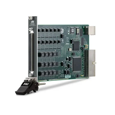
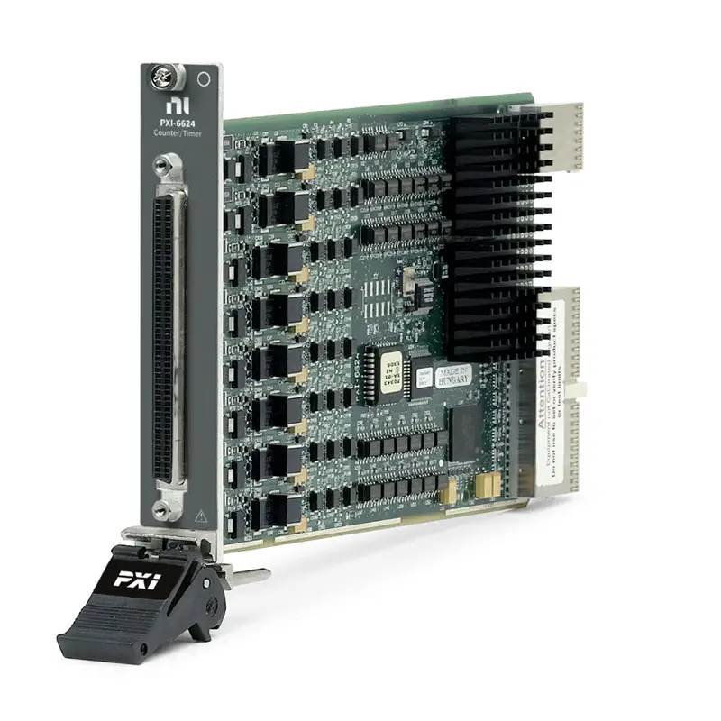
Product Introduction
The PXI‑6624 is an isolated 48 VDC, eight-channel PXI counter/timer module designed for industrial event counting, frequency measurement, encoder monitoring, pulse measurement and pulse generation applications.
The module provides eight 32-bit up/down counters, 26 isolated digital inputs and eight isolated sinking digital outputs. Its channel-to-channel isolation and support for signals up to 48 VDC make it suitable for connecting industrial sensors, encoders, switches, actuators and production equipment to a PXI test system.
The PXI‑6624 supports event counting, period and frequency measurement, quadrature encoder measurement, pulse-width measurement, retriggerable pulse generation, buffered event counting and continuous pulse-train generation.
Product Overview
The National Instruments PXI‑6624 belongs to the NI counter/timer device family. Its standard NI part number is 778975‑01.
Unlike general-purpose TTL counter/timer modules, the PXI‑6624 provides isolated industrial I/O capable of working with signals up to 48 VDC.
A typical system architecture is:
Industrial Sensor / Encoder / DUT ↔ PXI‑6624 ↔ PXI Chassis ↔ PXI Controller ↔ Test Software
The isolated inputs receive events, encoder phases, gates and trigger signals. The onboard counters perform timing and counting functions, while the isolated outputs generate pulses or control compatible external loads.
Key Features
Eight 32-Bit Counter/Timers
The PXI‑6624 provides eight independent 32-bit up/down counter/timers.
Each counter can support functions such as:
- Event counting
- Period measurement
- Frequency measurement
- Pulse-width measurement
- Two-signal edge separation measurement
- Quadrature encoder position measurement
- Pulse generation
- Pulse-train generation
- Retriggerable pulse generation
The 32-bit counter resolution provides a maximum count value of 4,294,967,295 before rollover.
26 Isolated Digital Inputs
The PXI‑6624 provides 26 isolated digital inputs, including three input terminals associated with each counter and two additional programmable function inputs.
These input channels can connect to:
- Proximity sensors
- Photoelectric sensors
- Mechanical switches
- Quadrature encoders
- Industrial pulse sources
- External gates
- Trigger signals
- Machine-status outputs
Each input uses a driven reference connection to either supply or ground, with two terminals provided per input.
Eight Isolated Digital Outputs
The module provides eight isolated sinking digital outputs, with one output associated with each counter.
The outputs support load voltages from 5 VDC to 48 VDC and switching currents up to 100 mA per channel.
They can be used for:
- Pulse generation
- Pulse-train generation
- External triggering
- Indicator control
- Relay or interface control through suitable circuits
- Machine sequencing
- Test-fixture control
Up to 48 VDC Industrial I/O
The isolated inputs accept signals up to 48 VDC, and the sinking outputs support external load supplies from 5 VDC to 48 VDC.
This voltage capability allows the PXI‑6624 to interface with industrial devices that operate above conventional 3.3 V or 5 V TTL logic levels.
Channel-to-Channel Isolation
The PXI‑6624 provides 60 VDC channel-to-channel isolation and 60 VDC channel-to-earth-ground isolation for Measurement Category I applications.
Isolation can help:
- Break unwanted ground-current paths
- Reduce the effects of ground-potential differences
- Protect low-voltage PXI system circuitry
- Connect sensors using different reference potentials
- Improve reliability in industrial test environments
The module is not intended for direct connection to MAINS circuits or Measurement Categories II, III or IV.
400 kHz Isolated Input and Output Operation
The isolated digital inputs support frequencies up to 400 kHz. The isolated outputs also support switching frequencies up to 400 kHz under the specified load and wiring conditions.
The documented minimum input and output pulse width is 1 µs.
These specifications make the module suitable for industrial counters, encoders and pulse signals while maintaining isolated I/O.
20 MHz Maximum Counter Source Frequency
The counter/timer circuitry supports a maximum source frequency of 20 MHz.
Available internal base clocks include:
- 100 kHz timebase
- 20 MHz timebase
The base-clock accuracy is 50 ppm over the specified temperature range.
Buffered Counter Measurements
The PXI‑6624 supports DMA and interrupt-based data transfer for counter/timer applications.
Buffered capabilities can be used for:
- Continuous event counting
- Buffered period measurement
- Buffered frequency measurement
- Timestamped edge acquisition
- Continuous pulse-train measurement
- Encoder position recording
DMA resources are available for up to three channels simultaneously, depending on the configured measurement task.
PXI Trigger Bus Integration
The PXI‑6624 can use PXI timing and triggering resources to coordinate its counter/timer functions with other modules in the system.
Available PXI resources include:
- Six PXI trigger lines
- One PXI star trigger
- One PXI clock
This integration is useful for synchronized automated test, multi-module event measurement and coordinated pulse generation.
Technical Specifications
| Parameter | Specification |
|---|---|
| Product Type | Isolated PXI Counter/Timer Module |
| Model | PXI‑6624 |
| Part Number | 778975‑01 |
| Manufacturer | National Instruments |
| Bus Interface | PXI Hybrid |
| Counter/Timers | 8 Up/Down Counters |
| Counter Resolution | 32 Bits |
| Maximum Count | 4,294,967,295 |
| Maximum Counter Source Frequency | 20 MHz |
| Available Base Clocks | 100 kHz and 20 MHz |
| Base-Clock Accuracy | 50 ppm over Temperature |
| Isolated Digital Inputs | 26 |
| Maximum Input Frequency | 400 kHz |
| Minimum Input Pulse Width | 1 µs |
| Input Voltage Range | Up to 48 VDC |
| Typical Input ON Voltage | 2.5 V |
| Guaranteed Input ON Voltage | 4.1 V |
| Guaranteed Input OFF Voltage | 0.8 V |
| Isolated Digital Outputs | 8 |
| Output Type | Sinking, Low-Side Switch |
| Output Load Voltage Range | 5 VDC to 48 VDC |
| Maximum Switching Current | 100 mA per Channel |
| Maximum Inrush Current | 600 mA per Channel |
| Maximum Output Frequency | 400 kHz |
| Minimum Output Pulse Width | 1 µs |
| Channel-to-Channel Isolation | 60 VDC, Measurement Category I |
| Channel-to-Earth Isolation | 60 VDC, Measurement Category I |
| Data Transfer | DMA for up to 3 Channels and Interrupts |
| PXI Trigger Lines | 6 |
| PXI Star Trigger | 1 |
| PXI Clock | 1 |
| I/O Connector | 100-Pin Female SCSI-II Type |
| Recommended Cable | SH100M-100M Flex Cable |
| Recommended Connector Blocks | SCB-100A or CB-100 |
| Operating Temperature | 0°C to 55°C |
| Storage Temperature | −20°C to 70°C |
| Dimensions | 16.0 cm × 10.0 cm |
| Primary Applications | Event Counting, Frequency Measurement, Encoder Monitoring and Pulse Generation |
How Does the PXI‑6624 Work?
The PXI‑6624 receives isolated industrial signals through its digital inputs and routes them to the onboard counter/timer circuitry.
A simplified measurement path is:
Sensor / Encoder / Pulse Source → Isolated Input → 32-Bit Counter → DMA / Interrupt → PXI Controller
For output applications, the signal path is:
PXI Application → Counter Timing Engine → Isolated Sinking Output → External Load or DUT
The counter measures edges against an internal or external timebase. Software configures the counter task, source, gate, auxiliary input, direction, triggering and data-transfer method.
PXI‑6624 Counter Architecture
Each counter can use multiple signals to perform advanced measurement and generation tasks.
Depending on the application, counter terminals can be configured as:
- Source
- Gate
- Auxiliary input
- Output
- Encoder phase A
- Encoder phase B
- Encoder index
The 26 input channels provide three inputs per counter plus two additional PFI channels. This architecture supports more complex tasks than basic single-input event counting.
Event Counting
The PXI‑6624 can count rising or falling edges from industrial sensors, switches, encoders and other pulse-producing devices.
Typical event-counting applications include:
- Parts counting
- Machine-cycle counting
- Production throughput monitoring
- Rotational event counting
- Flow-meter pulse counting
- Limit-switch monitoring
- Batch counting
The 32-bit counter provides a large count range, and buffered operation can record changes over time.
Frequency Measurement
The PXI‑6624 can measure the frequency of periodic industrial signals.
Frequency measurements can be used for:
- Motor-speed monitoring
- Rotational-speed measurement
- Fan-speed measurement
- Flow-meter monitoring
- Pulse-source verification
- Production equipment diagnostics
The isolated input stage supports external signal frequencies up to 400 kHz, while the internal counter circuitry supports source frequencies up to 20 MHz.
Period Measurement
Period measurement determines the time between consecutive edges of an input signal.
This function can be useful when:
- The input frequency is relatively low
- Time between machine events must be measured
- Rotational period must be monitored
- Pulse timing variation must be analyzed
- Cycle duration must be verified
Pulse-Width Measurement
The PXI‑6624 can measure the time between the rising and falling edges of an isolated input pulse.
Pulse-width measurement can be used for:
- Duty-cycle analysis
- Actuator timing verification
- Pulse-output sensor testing
- Control-signal validation
- Industrial controller testing
Two-Signal Edge Separation Measurement
Two-signal edge separation measures the time between an edge on one input and an edge on another input.
This capability can support:
- Sensor-response timing
- Actuator delay measurement
- Propagation-delay testing
- Sequence verification
- Machine timing analysis
- Trigger-to-response measurement
Quadrature Encoder Measurement
The PXI‑6624 can connect to compatible quadrature encoders through isolated input channels.
Quadrature encoder measurements can determine:
- Position
- Direction
- Relative motion
- Rotational displacement
- Linear displacement when used with a suitable encoder
Phase A and phase B signals indicate movement and direction, while the optional index signal can provide a reference position.
Pulse Generation
Each counter can generate timed pulses through an associated isolated sinking output.
Generated pulses can be used for:
- Triggering external equipment
- Stimulating a DUT
- Controlling a test fixture
- Simulating a sensor output
- Generating timed machine-control signals
- Validating industrial inputs
The external load must be compatible with the sinking-output architecture and the 5 VDC to 48 VDC load-supply range.
Pulse-Train Generation
The PXI‑6624 can generate continuous or finite pulse trains with programmable timing.
Pulse trains can be used for:
- Clock generation
- Motor and motion-interface testing
- Sensor simulation
- Frequency-response testing
- Production fixture control
- Device synchronization
Retriggerable Pulse Generation
A retriggerable pulse task allows each qualifying trigger event to initiate or extend a configured output pulse.
This function is useful for:
- Watchdog-style timing
- Missing-pulse detection systems
- Event-controlled output extension
- Industrial alarm timing
- Trigger conditioning
Continuous Buffered Event Counting
Buffered event counting records counter values at defined sample events rather than reading only the current total.
This allows engineers to examine how event counts change over time and correlate counter measurements with other system data.
Possible applications include:
- Production-rate monitoring
- Position tracking
- Flow accumulation
- Machine-cycle analysis
- Timestamp-related event recording
Industrial Isolation and Protection
The PXI‑6624 is designed for isolated industrial signals rather than direct TTL-only interfaces.
Input protection includes current limiting and reverse/overvoltage protection up to the documented limits.
The output circuitry includes short-circuit behavior that disables the affected output and periodically retries until the fault is removed.
Before connecting signals, verify:
- Signal voltage
- Input current
- Output load voltage
- Output load current
- Channel reference connection
- Isolation potential
- Measurement category
- Cable and connector wiring
Sinking Digital Output Operation
The PXI‑6624 outputs are low-side sinking switches. They do not source the load voltage.
A typical output connection is:
External Positive Supply → Load → PXI‑6624 Output → Output Reference
When the output turns on, it provides a current path toward the reference terminal.
The external supply and load must be selected so that channel voltage, switching current and total system limits are not exceeded.
PXI Triggering and Synchronization
The PXI‑6624 can route timing and trigger signals through the PXI backplane.
This enables coordination with compatible:
- Data acquisition modules
- Digitizers
- Waveform generators
- Digital I/O modules
- Additional counter/timer modules
- PXI timing and synchronization modules
Backplane triggering reduces the need for external cabling between modules and can simplify synchronized test-system design.
PXI System Requirements
The PXI‑6624 is a module and cannot operate independently.
A complete system normally requires:
- PXI‑6624 counter/timer module
- Compatible PXI or PXIe chassis with a compatible hybrid slot
- Compatible PXI controller or remote-control connection
- 100-pin cable
- Compatible terminal block or connector accessory
- NI‑DAQmx driver
- Compatible measurement or test software
Cables and Connector Accessories
The PXI‑6624 uses a 100-pin female SCSI-II-type I/O connector.
Common connectivity options include:
- SH100M-100M Flex Cable: 100-pin shielded cable for connecting the module to compatible accessories
- SCB-100A: shielded connector block for signal wiring and noise reduction
- CB-100: connector kit for DIN-rail, panel or desktop installation
Verify connector-block compatibility, cable length and terminal pinout before wiring the DUT.
Automotive and Aerospace Testing
The isolated counter and digital I/O architecture makes the PXI‑6624 suitable for selected automotive and aerospace test systems.
Potential applications include:
- Rotational-speed measurement
- Encoder monitoring
- Actuator timing
- Pulse-output sensor validation
- Subsystem response measurement
- Automated functional testing
- Hardware-in-the-loop interface monitoring
Industrial and Motion Applications
The PXI‑6624 can connect to compatible industrial sensors and encoders in motion and machine-monitoring systems.
Potential applications include:
- Conveyor position monitoring
- Motor-speed measurement
- Machine-cycle counting
- Quadrature encoder acquisition
- Limit-switch monitoring
- Production equipment timing
- Industrial pulse generation
The PXI‑6624 is a measurement and test module and should not be treated as a complete safety-rated motion controller.
Manufacturing Test
The module can be integrated into production systems that need to measure or generate isolated industrial timing signals.
A typical manufacturing test sequence may include:
- Initialize the PXI system and NI‑DAQmx task.
- Configure the required counter input or output channels.
- Set the timebase, edge and triggering options.
- Apply power to the external sensor or load circuit.
- Generate a test stimulus when required.
- Measure frequency, period, pulse width or event count.
- Compare the result with the acceptance limits.
- Record the result and pass/fail status.
System Integration Considerations
Before selecting the PXI‑6624, verify:
- Required number of counters
- Required counter resolution
- Input signal voltage
- Input signal frequency
- Required pulse-width range
- Encoder signal type
- Output load voltage
- Output switching current
- Need for channel-to-channel isolation
- Required DMA channels
- PXI trigger requirements
- Compatible chassis slot
- Connector block and cable requirements
- NI‑DAQmx and operating-system compatibility
Troubleshooting PXI‑6624 Systems
If the PXI‑6624 does not count, measure or generate signals correctly, check the hardware, wiring and software configuration.
- Verify that the module is detected in NI Measurement & Automation Explorer.
- Confirm that the correct NI‑DAQmx driver is installed.
- Check the selected counter and terminal assignments.
- Verify the source, gate and auxiliary input configuration.
- Confirm signal voltage and current levels.
- Check input-reference wiring.
- Verify the sinking-output external supply and load connection.
- Confirm that the input frequency does not exceed 400 kHz.
- Check the selected internal or external timebase.
- Verify edge polarity and encoder configuration.
- Check PXI trigger routing.
- Inspect the 100-pin cable and terminal-block wiring.
- Test the channel with NI‑MAX or a basic NI‑DAQmx example.
How to Choose a PXI Counter/Timer Module
Before purchasing a PXI counter/timer module, determine:
- Required number of counters
- Required counter resolution
- Maximum input frequency
- Required industrial voltage range
- Need for isolation
- Required digital input count
- Required digital output count
- Sourcing or sinking output requirements
- Encoder measurement requirements
- Buffered measurement requirements
- Pulse-generation requirements
- PXI chassis and software compatibility
Industries
- Industrial Automation
- Motion and Position Measurement
- Automotive Testing
- Aerospace Testing
- Manufacturing Test
- Electronics Production
- Machine Monitoring
- Research and Development
- Automated Test Equipment
Applications
Event Counting
The PXI‑6624 can count isolated pulses from sensors, switches, machines and industrial equipment.
Frequency and Period Measurement
The module can measure the frequency or period of compatible pulse signals for rotational-speed, flow and timing applications.
Quadrature Encoder Measurement
Three inputs per counter support phase A, phase B and index signals from compatible quadrature encoders.
Pulse-Width Measurement
The PXI‑6624 can measure the active duration of industrial pulse signals for duty-cycle and response-timing analysis.
Pulse and Pulse-Train Generation
Eight isolated sinking outputs can generate programmable pulses and pulse trains for compatible loads and test fixtures.
Automated Manufacturing Test
Counter measurements and isolated digital outputs can be incorporated into automated pass/fail test sequences.
PXI‑6624 vs PCI‑6624
| Feature | PXI‑6624 | PCI‑6624 |
|---|---|---|
| Bus Interface | PXI Hybrid | PCI |
| Counter/Timers | 8 | 8 |
| Counter Resolution | 32 Bits | 32 Bits |
| Isolated Inputs | 26 | 26 |
| Isolated Outputs | 8 | 8 |
| PXI Trigger Bus | Supported | Not Available |
| System Type | Modular PXI Test System | Desktop Computer with PCI Slot |
| Part Number | 778975‑01 | 778834‑01 |
Both models provide similar isolated counter/timer functionality. The PXI‑6624 is the appropriate version for modular PXI systems requiring backplane triggering and integration with other PXI instruments.
PXI‑6624 vs Standard TTL Counter/Timer Modules
| Feature | PXI‑6624 | Standard TTL Counter/Timer |
|---|---|---|
| Input Voltage | Up to 48 VDC | Typically 5 V TTL |
| Channel Isolation | 60 VDC Channel-to-Channel | Often Nonisolated |
| Digital Inputs | 26 Isolated Inputs | Model Dependent |
| Digital Outputs | 8 Isolated Sinking Outputs | Usually TTL Logic Outputs |
| Maximum Isolated I/O Frequency | 400 kHz | Potentially Higher |
| Best For | Industrial Sensors and Control Signals | Low-Voltage Electronic Signals |
Choose the PXI‑6624 when isolation and industrial voltage compatibility are more important than the higher edge rates available from nonisolated TTL counter/timer hardware.
Recommended Related Products
| PCI‑6624 | PCI version of the isolated eight-channel counter/timer device for compatible desktop computers. |
| PXI‑6602 | PXI counter/timer module for high-speed TTL event counting, frequency measurement and pulse generation. |
| PXIe‑6612 | PXI Express counter/timer module for advanced timing, encoder and digital pulse applications. |
| SH100M-100M | 100-pin shielded cable for connecting the PXI‑6624 to compatible terminal accessories. |
| SCB-100A | Shielded 100-pin connector block for organized PXI‑6624 signal wiring. |
| NI PXI Modules | Modular instruments for timing, data acquisition, digital I/O and automated test systems. |
Why Choose PXI‑6624?
- Eight 32-bit up/down counter/timers
- 26 isolated digital inputs
- Eight isolated sinking digital outputs
- Input voltage support up to 48 VDC
- Output load range from 5 VDC to 48 VDC
- 60 VDC channel-to-channel isolation
- Input and output frequencies up to 400 kHz
- Maximum counter source frequency of 20 MHz
- Event, period and frequency measurement
- Pulse-width and edge-separation measurement
- Quadrature encoder support
- Pulse and pulse-train generation
- Buffered counter measurements
- PXI trigger bus integration
- Suitable for industrial and manufacturing test
Frequently Asked Questions
What is the PXI‑6624?
The PXI‑6624 is an isolated 48 VDC PXI counter/timer module with eight 32-bit counters, 26 digital inputs and eight sinking digital outputs.
What is the part number for the PXI‑6624?
The standard National Instruments part number for the PXI‑6624 is 778975‑01.
How many counters does the PXI‑6624 provide?
The module provides eight independent 32-bit up/down counter/timers.
What is the maximum counter value?
Each 32-bit counter can count up to 4,294,967,295 before rollover.
How many digital inputs does the PXI‑6624 have?
The PXI‑6624 provides 26 isolated digital inputs, including three inputs per counter and two additional PFI inputs.
How many digital outputs does the PXI‑6624 have?
It provides eight isolated sinking digital outputs, with one output associated with each counter.
What input voltage does the PXI‑6624 support?
The isolated inputs support compatible signals up to 48 VDC.
What is the maximum isolated input frequency?
The isolated inputs support frequencies up to 400 kHz.
What is the maximum counter source frequency?
The onboard counter circuitry supports a maximum source frequency of 20 MHz.
Does the PXI‑6624 support quadrature encoders?
Yes. It supports compatible quadrature encoder phase A, phase B and index signals.
Can the PXI‑6624 generate pulses?
Yes. It can generate single pulses, retriggerable pulses, finite pulse trains and continuous pulse trains through its isolated sinking outputs.
Are the PXI‑6624 outputs sourcing or sinking?
The outputs are sinking low-side switches. They require a compatible external load supply from 5 VDC to 48 VDC.
Does the PXI‑6624 provide channel-to-channel isolation?
Yes. The module provides 60 VDC channel-to-channel and channel-to-earth-ground isolation for Measurement Category I applications.
Can the PXI‑6624 connect directly to MAINS voltage?
No. It is intended for Measurement Category I circuits and must not be used for direct measurements in Categories II, III or IV.
Does the PXI‑6624 require a PXI chassis?
Yes. It must be installed in a compatible PXI or PXIe hybrid slot and used with a PXI controller or remote-control connection.
Which driver does the PXI‑6624 use?
The PXI‑6624 uses the NI‑DAQmx driver for counter/timer configuration, measurement and generation tasks.
Which cable is used with the PXI‑6624?
A common compatible option is the SH100M-100M Flex cable, used with a suitable SCB-100A or CB-100 connector accessory.
What should I check before purchasing the PXI‑6624?
Verify the required counter functions, input voltage and frequency, output load voltage and current, isolation requirements, chassis slot, cable, connector block, software compatibility and exact part number.
Conclusion
The PXI‑6624 Isolated 48 VDC Counter/Timer Module provides eight 32-bit counters, 26 isolated digital inputs and eight isolated sinking outputs for industrial timing and control-signal applications. Its support for event counting, frequency and period measurement, quadrature encoders, pulse measurement, pulse generation and PXI synchronization makes it suitable for automotive, aerospace, motion, industrial automation and manufacturing test systems.















