






Product Introduction
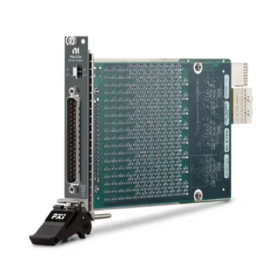
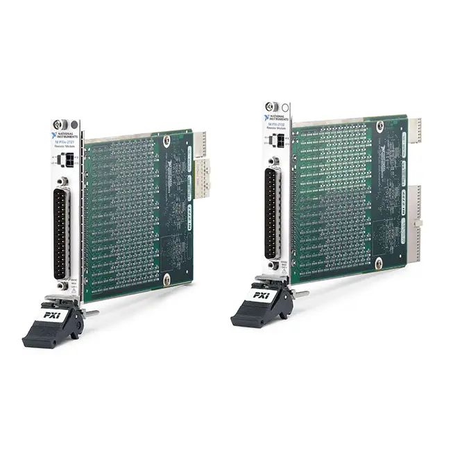
The NI PXIe-2727 is a 16-bit, 9-channel PXI Express programmable resistor module designed for resistance-based sensor simulation, hardware-in-the-loop (HIL) validation, ECU testing, automated electronic test, and environmental condition simulation.
The PXIe-2727 provides 9 independent programmable resistor channels with resistance values from 0.25 Ω to 16,320 Ω per channel and 0.25 Ω resolution. The module programmatically controls a network of relays to vary the resistance presented across each channel.
This architecture allows the PXIe-2727 to reproduce the electrical behavior of resistance-based devices such as potentiometers, resistance temperature detectors (RTDs), voltage dividers, and bridge elements. It is particularly useful for automated HIL and controller validation systems where physical environmental conditions must be simulated electrically.
Product Overview
The National Instruments PXIe-2727 belongs to the NI 272x family of programmable resistor modules. Unlike conventional switch modules that primarily route signals, the PXIe-2727 is specifically designed to create programmable resistance values under software control.
Each of its nine channels provides a wide programmable resistance range, allowing a test system to automatically reproduce different sensor states and operating conditions without manually replacing resistors.
With 16-bit architecture and 0.25 Ω resistance steps, the PXIe-2727 is particularly useful for applications requiring a wider resistance range and finer resistance control than lower-resolution programmable resistor modules.
Key Features
9 Independent Programmable Resistor Channels
The PXIe-2727 provides 9 independent programmable resistor channels within a single PXI Express module.
- 9 programmable resistor channels
- Independent channel architecture
- Software-controlled resistance
- Automated resistance configuration
- Multi-sensor simulation
- Automated HIL integration
Advantage: Multiple resistance-based sensor interfaces can be simulated simultaneously from one PXI Express module.
16-Bit Programmable Resistor Architecture
The PXIe-2727 uses a 16-bit programmable resistor architecture, providing significantly finer resistance control and a wider resistance range than 8-bit members of the NI 272x family.
- 16-bit architecture
- Fine resistance adjustment
- Wide programmable resistance range
- Automated resistance sweeps
- High-resolution sensor simulation
0.25 Ω to 16,320 Ω Resistance Range
Each PXIe-2727 channel provides a programmable resistance range from 0.25 Ω to 16,320 Ω.
| Parameter | PXIe-2727 |
|---|---|
| Programmable Resistance Range | 0.25 Ω to 16,320 Ω per Channel |
| Resistance Resolution | 0.25 Ω |
| Number of Channels | 9 |
| Architecture | 16 Bit |
Advantage: The wide resistance range makes the module suitable for simulating many different resistance-based devices and sensor interfaces.
0.25 Ω Resistance Resolution
The PXIe-2727 provides 0.25 Ω resistance steps, allowing software to make relatively fine adjustments across the programmable range.
- 0.25 Ω resistance resolution
- Fine resistance adjustment
- Automated sensor simulation
- Resistance sweep testing
- Controller characterization
60 VDC Maximum Channel Voltage
The PXIe-2727 supports channel-to-channel voltages up to 60 VDC or 30 VACrms, CAT I.
The module is intended for test and measurement circuits and is not designed for direct connection to mains installations in CAT II, CAT III, or CAT IV environments.
0.3 A Maximum Current per Channel
Each PXIe-2727 programmable resistor channel supports a maximum current of 0.3 A, subject to the module’s voltage, resistance, and power limitations.
When designing a test system, engineers should verify that the DUT operating conditions remain within all specified electrical limits.
0.25 W Maximum Power per Channel
The maximum power rating is 0.25 W per channel.
Voltage, current, resistance, and power limits must be considered together when determining whether a specific sensor or DUT interface can be simulated safely.
RTD Simulation
The PXIe-2727 can reproduce programmable resistance values for compatible resistance temperature detector applications.
- RTD simulation
- Temperature sensor emulation
- Temperature controller testing
- ECU temperature-input validation
- Environmental condition simulation
Advantage: Software can translate simulated temperature conditions into corresponding resistance values, allowing automated testing without physically changing temperature.
Potentiometer Simulation
The PXIe-2727 can be used to reproduce resistance conditions associated with compatible potentiometer-based interfaces.
- Potentiometer simulation
- Position sensor emulation
- Controller input validation
- Automated position-state testing
- Resistance-based control simulation
Voltage Divider Simulation
Programmable resistance can be incorporated into voltage-divider test circuits to reproduce different electrical operating conditions.
- Voltage divider simulation
- Sensor interface validation
- Controller input characterization
- Automated resistance changes
- Electronic design validation
Bridge Element Simulation
The PXIe-2727 can also be used in compatible bridge-element simulation applications.
- Bridge element simulation
- Resistance-based sensor emulation
- Automated bridge testing
- Controller interface validation
- HIL simulation
Hardware-in-the-Loop Testing
One of the primary applications of the PXIe-2727 is hardware-in-the-loop testing.
In a HIL system, a real electronic controller can be connected to simulated sensors, actuators, communication networks, and electrical loads.
The PXIe-2727 provides programmable resistance that can represent different resistance-based sensor conditions during these simulations.
- HIL validation
- ECU testing
- Sensor simulation
- Environmental condition simulation
- Automated fault testing
- Regression testing
Technical Specifications
| Parameter | Description |
|---|---|
| Product Type | PXI Express Programmable Resistor Module |
| Model | NI PXIe-2727 |
| Part Number | 781986-27 |
| Bus Interface | PXI Express |
| Programmable Resistor Architecture | 16 Bit |
| Number of Channels | 9 |
| Resistance Range per Channel | 0.25 Ω to 16,320 Ω |
| Resistance Resolution | 0.25 Ω |
| Resistor Accuracy | 0.5% |
| Temperature Coefficient of Resistance | 100 ppm |
| Typical Minimum Resistance | 2 Ω |
| Maximum Channel-to-Channel Voltage | 60 VDC / 30 VACrms, CAT I |
| Maximum Channel-to-Ground Voltage | 60 VDC / 30 VACrms, CAT I |
| Maximum Current | 0.3 A per Channel |
| Maximum Power | 0.25 W per Channel |
| Connector | 37-Pin D-Sub |
| Topology | Independent |
| Primary Applications | HIL Testing, RTD Simulation, Potentiometer Simulation, Sensor Emulation and ECU Validation |
How the PXIe-2727 Works
The PXIe-2727 programmatically controls a series of internal relays to configure the resistance presented across each channel of its I/O connector.
A typical automated test sequence can operate as follows:
- Test software defines a required sensor or resistance condition.
- The PXIe-2727 configures the appropriate programmable resistance.
- The DUT detects the simulated resistance-based input.
- Other PXI instruments measure or monitor the DUT response.
- The test software evaluates and records the result.
- The PXIe-2727 changes to the next resistance condition.
- The sequence repeats automatically.
This allows hundreds or thousands of test conditions to be executed without manually changing physical resistors or sensors.
Resistance-Based Sensor Simulation
Many physical sensors communicate changes in temperature, position, pressure, force, or other conditions through changes in electrical resistance.
When the sensor’s electrical characteristics fall within the PXIe-2727 operating specifications, the module can reproduce selected resistance conditions for controller validation.
Typical simulation targets include:
- Resistance temperature detectors (RTDs)
- Potentiometers
- Voltage-divider circuits
- Bridge elements
- Resistance-based sensor interfaces
RTD Temperature Simulation
Resistance temperature detectors change resistance according to temperature.
Instead of placing an RTD into a physical environmental chamber for every test point, an automated test system can program the PXIe-2727 to reproduce corresponding resistance conditions.
A typical workflow can be represented as:
Simulated Temperature → Required RTD Resistance → PXIe-2727 → Controller Input → DUT Response
This approach can substantially accelerate temperature-related controller validation when the electrical requirements are compatible with the PXIe-2727.
Automated Resistance Sweep Testing
The PXIe-2727 can automatically step through a sequence of resistance values to characterize DUT behavior across a defined operating range.
- Resistance sweep testing
- Threshold characterization
- Sensor response testing
- Calibration verification
- Boundary-condition testing
- Automated regression testing
At each resistance point, other PXI instruments can measure DUT voltage, current, timing, digital state, or communication response.
ECU and Controller Validation
Electronic control units frequently interface with resistance-based sensors. During development and production testing, engineers need to verify how the controller responds to normal, boundary, and abnormal sensor conditions.
The PXIe-2727 can automatically reproduce these resistance conditions as part of an ECU test system.
- ECU sensor-input validation
- Temperature-input testing
- Position-input testing
- Diagnostic validation
- Automated fault scenarios
- Production ECU testing
HIL System Integration
The PXIe-2727 can be integrated with other PXI modules to create a comprehensive HIL and controller validation platform.
A typical PXI HIL system may include:
- PXI Express chassis
- PXI embedded or remote controller
- PXIe-2727 programmable resistor module
- Analog input and output modules
- Digital I/O modules
- CAN / LIN communication interfaces
- PXI switch modules
- Counter/timer modules
- Fault-insertion hardware
Software can coordinate all of these instruments to simulate sensor conditions, communicate with the controller, inject faults, measure responses, and automatically evaluate test results.
PXIe-2727 vs PXIe-2725
The PXIe-2727 and PXIe-2725 belong to the same NI programmable resistor family but are optimized for different requirements.
| Feature | PXIe-2727 | PXIe-2725 |
|---|---|---|
| Resolution Architecture | 16 Bit | 8 Bit |
| Number of Channels | 9 | 18 |
| Resistance Range | Up to approximately 16 kΩ | Up to approximately 255 Ω |
| Resistance Step | 0.25 Ω | 1 Ω Class Architecture |
| Primary Advantage | Wide Range and Fine Resolution | Higher Channel Density |
| Best Application | Wide-Range Precision Sensor Simulation | High-Channel-Count Low-Resistance Simulation |
Choose the PXIe-2727 when resistance range and resolution are more important. Choose the PXIe-2725 when a larger number of programmable resistor channels is the primary requirement.
PXIe-2727 vs Fixed Resistors
| Feature | PXIe-2727 | Fixed Resistors |
|---|---|---|
| Resistance Selection | Software Controlled | Manual |
| Resistance Sweep | Automated | Requires Manual Changes |
| Multiple Test Conditions | Automated | Labor Intensive |
| HIL Integration | Designed for Automation | Requires Additional Hardware |
| Repeatability | High | Setup Dependent |
| Best Application | Automated Sensor Simulation | Simple Static Testing |
Connectivity and Accessories
The PXIe-2727 uses a 37-pin D-Sub connector and an independent programmable resistor topology.
Compatible connectivity options include the NI SH37F-37M shielded cable family and appropriate terminal accessories.
- 37-pin D-Sub interface
- SH37F-37M shielded cable compatibility
- Independent resistor channels
- Suitable for custom test-fixture integration
Industries
- Automotive Electronics
- Aerospace and Defense
- Industrial Automation
- Transportation Systems
- Electronic Manufacturing
- Hardware-in-the-Loop Testing
- Automated Test Equipment
- Research and Development
- Electronic Design Validation
Applications
Automotive ECU Testing
The PXIe-2727 can simulate compatible resistance-based automotive sensor inputs during ECU development, validation, and manufacturing testing.
RTD Simulation
The module can reproduce programmable resistance conditions associated with compatible RTD temperature sensors for automated temperature-input validation.
Potentiometer Simulation
Programmable resistance can reproduce selected potentiometer conditions for controller, position-sensor, and electronic interface testing.
Hardware-in-the-Loop Testing
The PXIe-2727 can form part of a HIL system that simulates the electrical environment surrounding a real electronic controller.
Manufacturing Test
Automated resistance configuration allows repetitive sensor-interface and controller tests to be performed efficiently in production environments.
Electronic Design Validation
The PXIe-2727 can automate resistance sweeps and sensor-interface conditions during prototype characterization and electronic design verification.
Recommended Related Products
| NI PXIe-2725 | 18-channel, 8-bit programmable resistor module recommended when higher channel density and lower resistance ranges are required. |
| NI PXIe-6612 | Counter/timer module for frequency, pulse, encoder, event-counting, and digital timing functions in automated controller test systems. |
| NI PXIe-4322 | Analog output module suitable for generating voltage and current stimulus alongside resistance-based sensor simulation. |
| NI PXI-8513 | CAN interface that can complement programmable resistor hardware in automotive ECU and HIL validation systems. |
Why Choose NI PXIe-2727?
- 16-bit programmable resistor architecture
- 9 independent resistor channels
- 0.25 Ω to 16,320 Ω programmable range per channel
- 0.25 Ω resistance resolution
- 0.5% resistor accuracy
- Up to 60 VDC channel voltage
- Up to 0.3 A per channel
- Software-controlled resistance
- RTD simulation
- Potentiometer simulation
- Voltage-divider simulation
- Bridge-element simulation
- Automated resistance sweeps
- Designed for HIL validation
- Suitable for ECU and controller testing
Frequently Asked Questions
What is the NI PXIe-2727?
The NI PXIe-2727 is a 16-bit, 9-channel PXI Express programmable resistor module designed for resistance-based sensor simulation, HIL testing, ECU validation, and automated electronic testing.
What is the part number of the PXIe-2727?
The NI PXIe-2727 part number is 781986-27.
How many programmable resistor channels does the PXIe-2727 have?
The PXIe-2727 provides 9 independent programmable resistor channels.
What is the resistance range of the PXIe-2727?
Each PXIe-2727 channel provides a programmable resistance range from 0.25 Ω to 16,320 Ω.
What is the resistance resolution of the PXIe-2727?
The resistance resolution is 0.25 Ω.
What is the maximum voltage of the PXIe-2727?
The PXIe-2727 supports up to 60 VDC or 30 VACrms, CAT I channel-to-channel and channel-to-ground.
What is the maximum current of the PXIe-2727?
The maximum specified current is 0.3 A per channel, subject to all applicable voltage, resistance, and power limitations.
What is the maximum power per channel?
The maximum power rating is 0.25 W per channel.
Can the PXIe-2727 simulate an RTD?
Yes. The PXIe-2727 is specifically designed for resistance-based simulation applications including compatible resistance temperature detectors (RTDs).
Can the PXIe-2727 simulate a potentiometer?
Yes. Potentiometers are one of the resistance-based devices that the PXIe-2727 is designed to emulate in compatible automated test systems.
Can the PXIe-2727 be used for HIL testing?
Yes. Hardware-in-the-loop validation is one of the primary applications of the PXIe-2727. It can reproduce resistance-based sensor conditions while a real controller operates within the HIL environment.
What is the difference between PXIe-2727 and PXIe-2725?
The PXIe-2727 provides 9 channels with a 16-bit architecture, 0.25 Ω resolution, and a resistance range extending to approximately 16 kΩ per channel. The PXIe-2725 provides 18 channels with an 8-bit architecture and is designed for lower-resistance, higher-channel-density applications.
What connector does the PXIe-2727 use?
The PXIe-2727 uses a 37-pin D-Sub connector. Compatible NI connectivity includes SH37F-37M shielded cables and appropriate terminal accessories.
What applications are suitable for the PXIe-2727?
Typical applications include RTD simulation, potentiometer simulation, voltage-divider simulation, bridge-element simulation, automotive ECU testing, HIL validation, automated resistance sweeps, controller testing, manufacturing test, and electronic design validation.
What should I check before purchasing a PXIe-2727?
Before purchasing a PXIe-2727, verify the required resistance range, 0.25 Ω resolution, nine-channel capacity, voltage and current requirements, per-channel power dissipation, required accuracy, connector and cabling requirements, PXI Express chassis compatibility, and the electrical characteristics of the sensor or DUT being simulated.
Conclusion
The NI PXIe-2727 16-Bit, 9-Channel PXI Programmable Resistor Module provides a programmable resistance range from 0.25 Ω to 16,320 Ω per channel with 0.25 Ω resolution. Its nine independent channels, wide resistance range, fine resistance control, and PXI Express integration make it particularly suitable for RTD simulation, potentiometer simulation, voltage-divider and bridge-element simulation, automotive ECU validation, hardware-in-the-loop testing, manufacturing test, and automated sensor-interface validation.















