






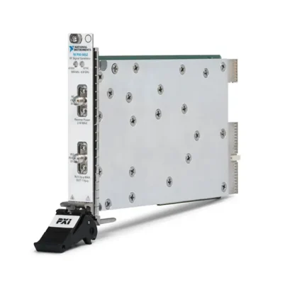
PXI-5651 3.3 GHz PXI RF Analog Signal Generator
The PXI-5651 is a single-channel PXI RF analog signal generator designed for automated RF testing, frequency-response measurements, receiver characterization, antenna testing and communications-system validation. It generates continuous-wave signals from 500 kHz to 3.3 GHz with maximum output power up to 12 dBm.
The module uses direct digital synthesis technology to provide fine frequency resolution, high-resolution frequency hopping and phase-continuous frequency sweeping. It also supports onboard FM, 2-FSK and on-off keying modulation without requiring an external arbitrary waveform generator.
Its compact single-slot 3U PXI format allows the PXI-5651 to operate with vector signal analyzers, digitizers, switches and other modular instruments in automated design-validation and production-test systems.
Key Features of the PXI-5651
- 500 kHz to 3.3 GHz frequency range
- Tunable down to 100 kHz with uncalibrated amplitude
- One RF output channel
- 12 dBm maximum output power
- 50 Ω nominal output impedance
- Continuous-wave RF signal generation
- Direct digital synthesis technology
- High-resolution frequency control
- Phase-continuous frequency sweeping
- Programmable frequency hopping
- 1.5 ms typical frequency tuning time
- FM modulation support
- Two-frequency FSK modulation support
- On-off keying modulation support
- Programmable phase modulation support through NI-RFSG
- -110 dBc/Hz phase noise at 1 GHz and 10 kHz offset
- 10 MHz external reference synchronization
- PXI trigger and timing integration
- NI-RFSG instrument-driver support
- Single-slot 3U PXI module
PXI-5651 Technical Specifications
| Product Model | PXI-5651 |
|---|---|
| Part Number | 779670-01 |
| Product Type | PXI RF analog signal generator |
| Number of Output Channels | 1 |
| Calibrated Frequency Range | 500 kHz to 3.3 GHz |
| Extended Frequency Tuning | Down to 100 kHz with uncalibrated amplitude |
| Maximum Output Power | 12 dBm |
| Output Impedance | 50 Ω nominal |
| Frequency Resolution | Less than 3 Hz below 1.3 GHz; less than 6 Hz from 1.3 GHz to 3.3 GHz |
| Typical Tuning Time | 1.5 ms |
| Supported Generation Mode | Continuous wave |
| Modulation Types | FM, 2-FSK and OOK; programmable PM support through NI-RFSG |
| Frequency Sweep | Phase-continuous DDS-based sweeping |
| Frequency Hopping | Software-programmable |
| Phase Noise | -110 dBc/Hz at 1 GHz carrier and 10 kHz offset |
| External Reference Frequency | 10 MHz |
| RF Reverse-Power Handling | Up to 0.5 W or +27 dBm under specified conditions |
| Maximum DC at RF Output | 25 VDC |
| Typical Output VSWR | Less than 1.8:1 from 500 kHz to 3.3 GHz |
| Driver | NI-RFSG |
| Module Format | 3U, single-slot PXI module |
| Operating Temperature | 0°C to 55°C |
| Life-Cycle Status | Discontinued |
| Recommended Replacement | PXIe-5651, part number 781216-01 |
PXI-5651 Part Number and Related Models
| Item | Part Number | Description |
|---|---|---|
| PXI-5651 | 779670-01 | 500 kHz to 3.3 GHz, single-channel PXI RF analog signal generator |
| PXIe-5651 | 781216-01 | PXI Express version recommended as the direct replacement for the PXI-5651 |
| PXIe-5652 | 781217-01 | 500 kHz to 6.6 GHz PXI Express RF analog signal generator |
| PXIe-5654 | Varies by frequency configuration | Higher-performance RF analog signal generator for applications up to 20 GHz |
The PXI-5651 and PXIe-5651 share the same basic 3.3 GHz RF generation function, but they use different chassis interfaces and part numbers. Confirm whether the existing system requires the legacy PXI version or the PXI Express replacement before ordering.
500 kHz to 3.3 GHz Frequency Coverage
The PXI-5651 generates calibrated RF signals from 500 kHz through 3.3 GHz. This range covers baseband and intermediate-frequency testing as well as many broadcast, industrial, navigation, automotive and wireless communication bands.
The module can also tune down to 100 kHz, but output-amplitude performance below the calibrated 500 kHz lower limit is not specified. Applications requiring traceable amplitude accuracy should remain within the calibrated frequency range.
12 dBm Maximum Output Power
The generator provides maximum output power as high as 12 dBm, depending on frequency and operating conditions. Programmable attenuation allows lower signal levels to be produced for receiver sensitivity, gain and threshold testing.
Maximum calibrated power can vary across the frequency range. Cable loss, switch insertion loss, attenuator accuracy and fixture loss should be included when determining the actual power delivered to the device under test.
Use a calibrated RF power meter or spectrum analyzer to verify the signal at the final test-plane reference point when accurate delivered power is required.
Direct Digital Synthesis
The PXI-5651 uses an onboard direct digital synthesis circuit for fine frequency adjustment and modulation. DDS technology enables precise control of the RF frequency while supporting phase-continuous changes between programmed settings.
The resulting frequency resolution is less than 3 Hz from 500 kHz to below 1.3 GHz and less than 6 Hz from 1.3 GHz through 3.3 GHz. This resolution is useful for receiver tuning tests, clock generation and narrow frequency-step measurements.
Phase-Continuous Frequency Sweeping
The generator can sweep between frequencies without introducing the large phase discontinuities associated with restarting an unrelated waveform at every point. Phase-continuous sweeping is useful for characterizing filters, amplifiers, antennas and complete RF signal paths.
A synchronized analyzer or power detector can measure the response at each frequency. Software can then calculate insertion loss, gain flatness or passband behavior across the programmed sweep.
High-Resolution Frequency Hopping
Frequency-list operation allows the PXI-5651 to move between predefined carrier frequencies under software or trigger control. Its typical tuning time is 1.5 ms, enabling faster automated measurements than many manually controlled signal sources.
Frequency hopping can be used to test receiver channel selection, scan multiple communication bands or apply a sequence of carrier frequencies during production testing.
Continuous-Wave Signal Generation
The PXI-5651 is primarily an RF continuous-wave source. Engineers can configure the carrier frequency and output power to provide a stable single-tone stimulus for RF components, receivers and test fixtures.
Common continuous-wave measurements include receiver sensitivity, amplifier gain, filter response, mixer conversion loss, switch insertion loss and antenna-path testing.
Frequency Modulation
Onboard FM generation varies the instantaneous carrier frequency according to the selected modulation waveform. Supported internal waveform types include sine, triangle and square modulation patterns.
FM capability can be used for receiver functional testing, tone-modulated carrier generation and communications experiments. The available frequency deviation depends on the RF carrier band and configured modulation settings.
Two-Frequency FSK Modulation
The PXI-5651 supports two-frequency frequency-shift keying. In 2-FSK operation, the carrier alternates between two frequency states to represent digital information.
This capability is useful for testing remote controls, keyless-entry systems, telemetry devices, industrial radios and other products using basic frequency-shift-keyed communication.
For a bit-error-rate test, the generator supplies the FSK stimulus while the test system controls the data pattern and compares the receiver output with the expected result.
On-Off Keying Modulation
On-off keying controls the RF carrier between enabled and suppressed states. It is a basic form of amplitude modulation frequently used by remote controls, low-cost wireless sensors, identification devices and keyless-entry transmitters.
OOK testing can evaluate whether a receiver correctly detects the presence and absence of the RF carrier at different signal levels, data rates and carrier frequencies.
Phase Modulation Support
The NI-RFSG programming interface includes phase-modulation controls for supported PXI and PXI Express 5650-series generators. Phase deviation can be configured programmatically for applications requiring basic PM stimulus.
The PXI-5651 is not a wideband arbitrary I/Q vector signal generator. Applications requiring complex QAM, OFDM, LTE, WLAN or other high-bandwidth vector waveforms should use an appropriate vector signal generator or vector signal transceiver.
Phase-Noise Performance
The PXI-5651 provides phase-noise performance of approximately -110 dBc/Hz at a 1 GHz carrier and 10 kHz offset under the specified conditions. Low phase noise helps preserve the purity of generated CW signals and improves adjacent-channel and receiver-selectivity measurements.
Observed phase noise depends on the carrier frequency, offset frequency, reference-clock source and measurement conditions. When testing sensitive receivers or oscillators, evaluate the complete phase-noise curve rather than relying on one offset value.
10 MHz Reference Synchronization
The module can lock to a compatible 10 MHz external reference. A common reference allows the signal generator and other RF instruments to share a consistent frequency standard.
Reference locking is useful when coordinating the PXI-5651 with a vector signal analyzer, frequency counter, digitizer or additional generator. Instruments locked to the same reference are frequency-coherent, but their RF output phases are not necessarily aligned.
PXI Trigger Integration
PXI trigger resources can coordinate frequency changes and signal-generation events with other instruments in the chassis. Triggered operation improves repeatability when the RF source must change state at a defined point in an automated sequence.
For example, a test application can configure the generator, arm a measurement instrument and then use a shared trigger to begin the required stimulus and acquisition.
RF Output Protection
The RF output is designed to tolerate limited reverse RF power and DC voltage under the conditions stated in the official specifications. Reverse-power handling is as high as 0.5 W or +27 dBm in supported configurations, and the specified maximum DC voltage is 25 V.
These values are protection limits rather than normal operating conditions. Use DC blocks, isolators, attenuators or other protective components when connecting the generator to powered circuits, transmitters or devices capable of returning energy to the RF output.
Typical PXI-5651 Applications
- RF receiver sensitivity testing
- Filter frequency-response characterization
- Amplifier gain testing
- Antenna and cable-path testing
- Bit-error-rate testing
- Keyless-entry system validation
- Remote-control receiver testing
- Clock and local-oscillator generation
- Frequency hopping tests
- FM receiver validation
- FSK and OOK device testing
- Automated production test
- RF component characterization
- Research and laboratory automation
Receiver Sensitivity Testing
The PXI-5651 can supply a controlled RF carrier to a receiver while test software reduces the power level. The receiver response can then be monitored to determine sensitivity, detection threshold or usable operating range.
For a valid sensitivity measurement, calibrate the complete RF path and account for cable, adapter, attenuator and switch losses. The signal reaching the receiver input may be lower than the level programmed at the generator output.
Filter and Amplifier Characterization
Frequency sweeps can characterize the gain or insertion loss of filters, amplifiers and other RF components. At every frequency point, a power meter, spectrum analyzer or vector signal analyzer measures the component output.
This setup can identify cutoff frequencies, passband ripple, gain flatness and out-of-band rejection. The measurement system should include path-loss correction and suitable attenuation to protect the receiving instrument.
Antenna and Cable Testing
The PXI-5651 can provide a programmable RF source for evaluating antennas, coaxial cable assemblies and wireless test fixtures. It is useful for relative transmission measurements when paired with a compatible receiver.
The PXI-5651 is not a vector network analyzer and does not directly measure S-parameters or impedance. Applications requiring calibrated reflection, return-loss and phase measurements should use a vector network analyzer.
Clock Generation
The fine DDS frequency resolution makes the PXI-5651 suitable for generating clocks at nonstandard sample rates. NI specifically identifies clocking WCDMA-related baseband and intermediate-frequency systems as an example application.
Before using the RF output as a clock source, verify that the receiving circuit accepts the generator’s sine-wave amplitude, impedance, offset and spectral characteristics.
Automated Production Testing
In production test systems, the PXI-5651 can generate repeatable RF stimulus across multiple frequencies and power levels. Test software can coordinate the generator with RF switches, analyzers, digital instruments and device-control interfaces.
Frequency lists and automated power changes reduce manual setup time. Test results can be compared with limits and stored automatically for traceability.
NI-RFSG Software Support
The PXI-5651 is controlled through the NI-RFSG instrument driver. NI-RFSG provides functions for setting frequency, output power, modulation, frequency lists, triggering and reference-clock configuration.
The driver supports LabVIEW and compatible text-based programming environments. Example programs and an interactive soft front panel can help engineers verify the hardware before integrating it into a complete test application.
Because the PXI-5651 is discontinued, confirm that the selected NI-RFSG release supports the operating system, PXI controller and application-development environment used by the test station.
Pairing the PXI-5651 with an RF Analyzer
The generator can be paired with a PXI-5661 Vector Signal Analyzer to create a modular stimulus-and-measurement system covering frequencies through 2.7 GHz.
The generator supplies a CW, FM, FSK or OOK signal, while the analyzer measures power, frequency, spectrum or modulation characteristics. A common reference clock and PXI triggering can improve frequency coordination and test repeatability.
PXI Chassis Integration
The PXI-5651 is a single-slot 3U module intended for a compatible PXI chassis. It can be installed alongside digitizers, signal analyzers, switches, counters and data-acquisition modules.
Before installation, verify chassis slot compatibility, controller support, cooling and the required NI-RFSG version. Power down the chassis before inserting or removing the module.
PXI-5651 Troubleshooting
The PXI-5651 is not detected in NI MAX
Confirm that the module is fully installed in a compatible PXI slot. Check chassis power, controller communication and NI-RFSG installation, then refresh the hardware list in NI Measurement & Automation Explorer.
No RF signal appears at the output
Verify that RF output is enabled and that generation has started. Check the programmed frequency and power, trigger configuration, RF cable and receiving instrument settings.
The output power is lower than expected
Measure cable, adapter, attenuator and switch losses. Confirm that the requested output level is supported at the selected frequency and verify that the receiving instrument uses a 50 Ω input.
The frequency is incorrect
Check the configured frequency units, reference-clock source and lock status. If an external reference is selected, verify that a compatible 10 MHz signal is present at the reference input.
The generator does not lock to the external reference
Inspect the reference cable and confirm the frequency, amplitude and 50 Ω termination of the external source. Allow sufficient time for the module to acquire lock after changing the reference configuration.
Frequency hopping is slower than expected
Use predefined frequency lists and hardware triggering where supported. Test throughput also depends on the receiving instrument, switching hardware, device-settling time and application software.
FM or FSK modulation does not look correct
Review the modulation waveform, rate and deviation settings. Confirm that the selected deviation is supported in the configured carrier-frequency range and that the analyzer bandwidth is wide enough to capture the complete modulated signal.
The OOK signal has unexpected timing
Check the modulation source, trigger route and data timing. Use an oscilloscope or RF analyzer with sufficient time resolution to verify the carrier’s on and off intervals.
The RF signal contains excessive spurious components
Allow the module to warm up and verify calibration status. Inspect the reference clock, grounding, shielding and external RF environment. Avoid overdriving amplifiers or other devices connected after the generator.
The RF output may have been exposed to reverse power
Disconnect the device under test and verify the generator output into a protected measurement instrument. Reverse-power protection does not guarantee continued accuracy after every overload condition. Return the module for evaluation if output level or spectral purity has changed.
PXI-5651 Comparison with Related RF Signal Generators
| Model | Primary Configuration | Best Suited For |
|---|---|---|
| PXI-5650 | 500 kHz to 1.3 GHz, FM, FSK and OOK | Lower-frequency RF and IF generation |
| PXI-5651 | 500 kHz to 3.3 GHz, 12 dBm maximum output | Legacy PXI RF testing through 3.3 GHz |
| PXI-5652 | 500 kHz to 6.6 GHz RF generation | Legacy PXI systems requiring higher carrier frequencies |
| PXIe-5651 | 500 kHz to 3.3 GHz PXI Express generator | Direct PXI Express replacement for PXI-5651 applications |
| PXIe-5652 | 500 kHz to 6.6 GHz with fast frequency switching | Higher-frequency PXI Express RF testing |
| PXIe-5654 | Up to 20 GHz with higher output power | Modern high-performance RF and microwave testing |
PXI-5651 vs PXI-5650
The PXI-5650 and PXI-5651 provide similar CW, FM, FSK and OOK capabilities. The principal difference is frequency coverage: the PXI-5650 reaches 1.3 GHz, while the PXI-5651 extends the upper frequency limit to 3.3 GHz.
Select the PXI-5651 for applications involving frequencies above 1.3 GHz. Choose the PXI-5650 only when the lower frequency range meets the requirement and compatibility with an existing system is essential.
PXI-5651 vs PXI-5652
The PXI-5651 generates signals through 3.3 GHz, while the PXI-5652 extends operation to 6.6 GHz. Both belong to the same general analog RF signal-generator family and support DDS frequency control and basic modulation.
The PXI-5651 is appropriate for applications below 3.3 GHz. The PXI-5652 is preferable for higher-frequency wireless standards, microwave components and test systems requiring coverage between 3.3 GHz and 6.6 GHz.
PXI-5651 vs PXIe-5651
The PXIe-5651 is the PXI Express replacement for the legacy PXI-5651. Both cover 500 kHz to 3.3 GHz and provide comparable continuous-wave and basic modulation capabilities.
The two versions use different chassis interfaces and part numbers. The PXIe-5651 is part number 781216-01, while the PXI-5651 is part number 779670-01. Confirm chassis compatibility before selecting either version.
PXI-5651 vs PXIe-5654
The PXIe-5654 is a newer, higher-performance analog RF signal generator available with frequency coverage up to 10 GHz or 20 GHz, depending on configuration. It also provides greater maximum output power and improved modern RF performance.
Choose the PXI-5651 to maintain a legacy 3.3 GHz PXI system. Consider the PXIe-5654 for new systems requiring higher frequency, additional power, faster tuning or longer-term platform support.
Recommended Related Products
- PXI-5650 1.3 GHz RF Signal Generator
- PXI-5652 6.6 GHz RF Signal Generator
- PXIe-5651 3.3 GHz RF Analog Signal Generator
- PXIe-5652 6.6 GHz RF Analog Signal Generator
- PXIe-5654 RF Analog Signal Generator
- PXI-5661 Vector Signal Analyzer
- PXI-5671 Vector Signal Generator
- View More NI PXI and PXI Express Modules
Selecting the Right RF Signal Generator
Choose the PXI-5651 when an existing PXI system requires a programmable RF source covering 500 kHz to 3.3 GHz with CW, FM, 2-FSK and OOK generation. It is particularly useful for maintaining validated production testers and legacy RF research systems.
Select the PXI-5652 when frequencies above 3.3 GHz are required. For a PXI Express chassis, consider the PXIe-5651 or PXIe-5652. Choose the PXIe-5654 for modern RF and microwave applications requiring substantially higher frequency coverage and output power.
Why Choose the PXI-5651?
- Covers RF and IF signals from 500 kHz to 3.3 GHz
- Provides maximum output power up to 12 dBm
- Generates continuous-wave RF signals
- Supports FM, 2-FSK and OOK modulation
- Provides fine DDS frequency resolution
- Supports phase-continuous frequency sweeps
- Offers 1.5 ms typical frequency tuning
- Locks to a compatible 10 MHz reference
- Integrates with PXI triggering and automated test systems
- Supports software control through NI-RFSG
Frequently Asked Questions
What is the PXI-5651?
The PXI-5651 is a single-channel PXI RF analog signal generator used for continuous-wave generation, frequency sweeping and basic RF modulation.
What is the PXI-5651 frequency range?
Its calibrated frequency range is 500 kHz to 3.3 GHz. It can tune down to 100 kHz, but amplitude performance below 500 kHz is not calibrated.
What is the maximum output power?
The maximum specified output power is 12 dBm, although the available calibrated level varies with frequency and operating conditions.
Which modulation types are supported?
The PXI-5651 supports FM, two-frequency FSK and on-off keying. NI-RFSG also provides supported phase-modulation controls for this device family.
Can the PXI-5651 generate complex I/Q waveforms?
No. It is an analog RF signal generator for CW and basic modulation. Use a vector signal generator when arbitrary I/Q, QAM, OFDM, LTE or WLAN waveforms are required.
What is the typical frequency tuning time?
The typical tuning time is 1.5 ms.
What is the PXI-5651 frequency resolution?
Frequency resolution is less than 3 Hz below 1.3 GHz and less than 6 Hz from 1.3 GHz to 3.3 GHz.
Does it support an external reference clock?
Yes. The PXI-5651 can lock to a compatible 10 MHz external reference signal.
Which driver controls the PXI-5651?
The module is controlled through the NI-RFSG instrument driver.
What is the PXI-5651 part number?
The standard NI part number is 779670-01.
Is the PXI-5651 still available from NI?
No. NI identifies the PXI-5651 as discontinued. Availability may be limited to used, refurbished or remaining surplus inventory.
What is the recommended PXI-5651 replacement?
NI lists the PXIe-5651, part number 781216-01, as the recommended replacement. It requires a compatible PXI Express or hybrid slot.
What should be checked before purchasing a used PXI-5651?
Verify the exact part number, PXI connector condition, RF output performance, calibration status and NI-RFSG compatibility. A complete test report should include frequency, output-power and basic spectral-performance checks.
Request a Quote for the PXI-5651
Contact us for current availability, test condition and project pricing for the PXI-5651 3.3 GHz PXI RF Analog Signal Generator. We can also help identify compatible RF cables, PXI chassis, vector signal analyzers and alternative PXI Express signal generators for your automated RF test system.















