






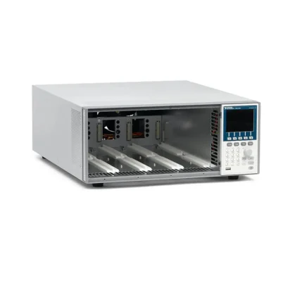
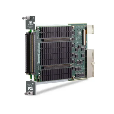
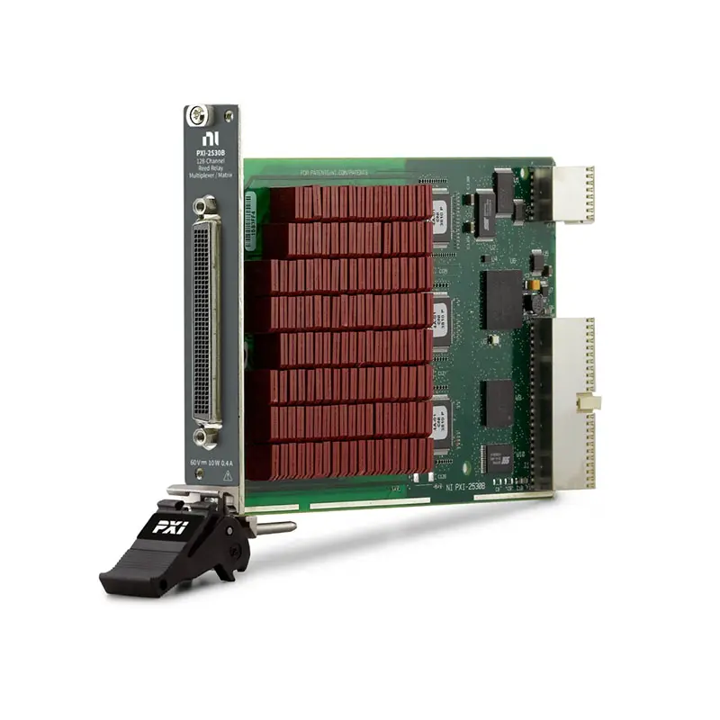
PXI-2530 128-Crosspoint PXI Multiplexer Matrix Switch
The PXI-2530 is a high-density PXI multiplexer and matrix switch module designed for automated test, data acquisition and measurement-system signal routing. It provides 128 reed-relay crosspoints that can be configured into seven different one-wire, two-wire and four-wire topologies.
The PXI-2530 supports maximum switching voltage up to 60 VDC or 30 Vrms, current up to 0.4 A and switching power up to 10 W per channel. Its flexible architecture makes it suitable for routing analog signals between sensors, devices under test and measurement instruments such as digital multimeters, digitizers and data acquisition modules.
The original PXI-2530 is discontinued. When replacing or expanding an existing system, verify the module revision and terminal-block compatibility because PXI-2530 accessories are not interchangeable with PXI-2530B accessories.
Key Features of the PXI-2530
- 128 reed-relay crosspoints
- Seven software-selectable multiplexer and matrix configurations
- One-wire, two-wire and four-wire signal routing
- 128×1 one-wire multiplexer configuration
- 64×1 two-wire multiplexer configuration
- 32×1 four-wire multiplexer configuration
- Eight-bank 16×1 one-wire multiplexer configuration
- 4×32 one-wire matrix configuration
- 8×16 one-wire matrix configuration
- 4×16 two-wire matrix configuration
- 60 VDC or 30 Vrms maximum switching voltage
- 0.4 A maximum switching current
- 10 W maximum switching power
- Greater than 15 MHz typical bandwidth in a 16×1 configuration
- Greater than 3 MHz typical bandwidth in a 128×1 configuration
- 555 µs relay operate and release time
- PXI hardware trigger support
- NI-SWITCH and NI Switch Executive compatibility
PXI-2530 Technical Specifications
| Product Model | PXI-2530 |
|---|---|
| Part Number | 778572-30; verify module revision when ordering |
| Product Type | PXI multiplexer and matrix switch module |
| Number of Crosspoints | 128 |
| Switch Type | Electromechanical reed relay |
| Supported Wire Modes | 1-wire, 2-wire and 4-wire |
| Multiplexer Topologies | 128×1 1-wire, 64×1 2-wire, 32×1 4-wire and eight banks of 16×1 1-wire |
| Matrix Topologies | 4×32 1-wire, 8×16 1-wire and 4×16 2-wire |
| Maximum Switching Voltage | 60 VDC or 30 Vrms, CAT I |
| Maximum Switching Current | 0.4 A |
| Maximum Switching Power | 10 W per channel |
| Typical Initial Path Resistance | Less than 2 Ω |
| Typical Thermal EMF | Less than 50 µV |
| Typical Bandwidth, 16×1 | Greater than 15 MHz in a 50 Ω system |
| Typical Bandwidth, 128×1 | Greater than 3 MHz in a 50 Ω system |
| Typical Channel Isolation | Greater than 60 dB at 200 kHz and greater than 40 dB at 1 MHz |
| Relay Operate Time | 555 µs |
| Relay Release Time | 555 µs |
| Simultaneously Driven Relays | 64 maximum |
| Mechanical Relay Life | 1 × 10⁹ cycles under no-load conditions |
| Input Trigger Sources | PXI trigger lines 0 through 7 and front-panel trigger |
| Minimum Input Trigger Pulse | 150 ns |
| Output Trigger Destinations | PXI trigger lines 0 through 7 and front-panel trigger |
| Programmable Output Pulse Width | 1 µs to 62 µs |
| Front-Panel Connector | 176-pin docking-station plug |
| Power Consumption | 1.2 W from 3.3 V and 4.2 W from 5 V |
| Operating Temperature | 0°C to 55°C |
| Storage Temperature | −20°C to 70°C |
| Module Format | 3U, one-slot PXI module |
| Dimensions | 21.6 × 2.0 × 13.0 cm |
| Weight | 400 g |
| Software Support | NI-SWITCH and NI Switch Executive |
| Lifecycle Status | Discontinued |
PXI-2530 Part Number and Accessories
| Item | Part Number | Description |
|---|---|---|
| PXI-2530 | 778572-30 | 128-crosspoint PXI multiplexer and matrix switch module; confirm the required revision |
| TB-2630 | 778733-01 | Terminal block for PXI-2530 multiplexer configurations |
| TB-2631 | 778734-01 | Terminal block for 4×32 one-wire and 4×16 two-wire matrix configurations |
| TB-2632 | 778735-01 | Terminal block for the 8×16 one-wire matrix configuration |
| 176-Pin PXI-2530 Cable | 780889-01 | Cable for connecting the original PXI-2530 to compatible accessories or fixtures |
A compatible terminal block is required to expose the signal connections and establish the selected topology. The TB-2630 supports multiplexer configurations, while the TB-2631 and TB-2632 support specific matrix configurations.
Compatibility warning: TB-2630, TB-2631 and TB-2632 accessories are intended for the original PXI-2530. They are not compatible with the PXI-2530B, which requires the corresponding B-series terminal blocks.
128-Crosspoint Reed-Relay Architecture
The PXI-2530 contains 128 independently controlled reed-relay crosspoints. The connected terminal block organizes these relays into the required multiplexer or matrix topology.
Reed relays provide physical contact isolation, low leakage and reliable routing for DC and moderate-frequency analog signals. The architecture supports measurement applications in which many test points must share one instrument or several sources and instruments must be interconnected dynamically.
The module can drive no more than 64 relays simultaneously. Route planning should account for this limit when the system requires multiple concurrent matrix connections.
Seven Supported Switch Configurations
| Configuration | Wire Mode | Recommended Accessory | Typical Use |
|---|---|---|---|
| 128×1 multiplexer | 1-wire | TB-2630 | Maximum single-ended channel density |
| 64×1 multiplexer | 2-wire | TB-2630 | Differential or paired-signal measurements |
| 32×1 multiplexer | 4-wire | TB-2630 | Four-wire resistance and Kelvin measurements |
| Eight banks of 16×1 | 1-wire | TB-2630 | Independent multiplexing groups |
| 4×32 matrix | 1-wire | TB-2631 | Connecting four buses to 32 test points |
| 8×16 matrix | 1-wire | TB-2632 | Additional row capacity and flexible routing |
| 4×16 matrix | 2-wire | TB-2631 | Differential matrix routing |
128×1 One-Wire Multiplexer
The 128×1 one-wire configuration routes one of 128 single-ended channels to a common connection. This topology provides the maximum channel density available from one PXI-2530 module.
It is suitable for scanning large numbers of voltage, sensor and monitoring signals into one measurement instrument. The common reference is handled separately through the terminal block and test fixture.
64×1 Two-Wire Multiplexer
The 64×1 two-wire configuration switches two conductors for every channel. It is appropriate for differential measurements, floating signals and applications where both signal connections must be routed together.
Two-wire switching can reduce errors caused by sharing a common return, although the complete system must still be designed for the source, instrument and grounding requirements.
32×1 Four-Wire Multiplexer
The 32×1 four-wire configuration routes four conductors per channel. It is commonly used for Kelvin resistance measurement, in which separate source and sense connections reduce the effect of cable and switch-path resistance.
When combined with an appropriate digital multimeter or source-measure instrument, this topology supports automated measurement of resistors, wiring assemblies, connectors and other low-resistance devices.
Eight-Bank 16×1 Multiplexer
The eight-bank configuration divides the module into eight independent 16×1 one-wire multiplexers. Each bank can be connected to a different instrument, stimulus source or subsystem.
This topology is useful when a test rack requires several smaller multiplexers rather than one large scanning structure. It can also reduce unnecessary wiring between independent signal groups.
4×32 One-Wire Matrix
The 4×32 matrix configuration allows four row buses to be connected to any of 32 columns. It supports flexible routing between multiple instruments and a larger group of test points.
Multiple nonconflicting crosspoints can be closed simultaneously, subject to the maximum relay-drive limit and the electrical constraints of the connected equipment.
8×16 One-Wire Matrix
The 8×16 configuration provides eight rows and 16 columns. It is useful when more instruments, sources or common buses must access a smaller number of device-under-test connections.
The TB-2632 terminal block is required for this topology. Verify the row and column assignments before designing the external cable or fixture.
4×16 Two-Wire Matrix
The 4×16 two-wire matrix routes paired conductors between four row groups and 16 column groups. It is suitable for differential signals and applications requiring simultaneous switching of high and low connections.
Two-wire matrix operation helps preserve paired-signal routing, but shielding and guarding connections may still require separate fixture wiring.
60 V and 0.4 A Switching
The PXI-2530 supports maximum switching voltage up to 60 VDC or 30 Vrms in Measurement Category I circuits. Maximum switching current is 0.4 A, and maximum switching power is 10 W per channel.
All three ratings must be respected simultaneously. A load that remains below the voltage or current limit can still exceed the permitted switching power.
The module is intended for signal-level test and measurement applications. It should not be used for mains distribution, high-energy power switching or circuits outside its specified measurement category.
Switching Bandwidth
Bandwidth depends on the selected topology and signal path. In a 50 Ω system, the typical bandwidth is greater than 15 MHz for a 16×1 one-wire configuration and greater than 3 MHz for the full 128×1 one-wire configuration.
Larger multiplexers generally have more connected relay and wiring capacitance, which reduces bandwidth. Cable length, terminal-block layout, source impedance, loading and fixture construction also affect the final system response.
Channel Isolation
The PXI-2530 provides typical channel-to-channel isolation greater than 60 dB at 200 kHz and greater than 40 dB at 1 MHz. Isolation decreases as signal frequency increases.
For applications involving low-level signals near higher-amplitude channels, use shielding, suitable grounding and careful route allocation. Separating sensitive and noisy signals can improve system-level crosstalk performance.
Path Resistance and Thermal EMF
The relay path has typical initial resistance below 2 Ω. The total measurement path also includes the terminal block, cable, fixture wiring and connectors.
Typical thermal EMF is below 50 µV. When measuring microvolt-level signals, manage temperature gradients and avoid placing high-current or heat-producing circuits near sensitive measurement connections.
Relay Life and Maintenance
The reed relays have a mechanical life of up to 1 × 10⁹ operations under no-load conditions. Electrical life depends on the switched voltage, current and load type.
Representative electrical endurance includes approximately 1 × 10⁸ cycles at 10 V and 100 mA, 5 × 10⁶ cycles at 25 V and 400 mA, and 1 × 10⁶ cycles at 60 V and 160 mA.
Switching capacitive or inductive loads can shorten relay life because of inrush current or arcing. External current limiting, flyback protection or transient suppression may be necessary.
PXI Hardware Triggering
The PXI-2530 accepts input triggers from PXI trigger lines 0 through 7 and from the front-panel trigger connection. The minimum input-trigger pulse width is 150 ns.
Output triggers can be routed to the PXI trigger bus or front-panel connection. Programmable output pulse widths from 1 µs to 62 µs allow switching operations to be coordinated with measurement instruments and automated test sequences.
Typical PXI-2530 Applications
- Automated data acquisition
- Digital multimeter channel expansion
- Production functional testing
- Electronic device validation
- Sensor and transducer scanning
- Differential voltage measurements
- Four-wire resistance measurements
- Continuity and cable testing
- Semiconductor characterization
- Matrix-based instrument routing
- Design verification testing
- Laboratory test automation
Digital Multimeter Channel Expansion
The PXI-2530 can expand a digital multimeter by routing many test points to one measurement input. One-wire topology provides maximum density, while two-wire topology supports differential measurements.
The four-wire topology can be used with a compatible DMM for Kelvin resistance measurements. A PXI-4072 digital multimeter can be combined with the switch in suitable legacy PXI measurement systems.
Automated Production Testing
In a production test system, the PXI-2530 can connect shared instruments to multiple device-under-test nodes without manual cable changes. Software-defined routes allow a test sequence to scan measurements or change signal connections automatically.
When the application requires continuous high-volume operation, review the switched load and expected relay count. Using the lowest practical voltage and current can extend electrical relay life.
Cable and Continuity Testing
Matrix configurations can connect measurement equipment to different conductors in a cable assembly or wiring harness. The test system can measure continuity, open circuits, resistance and unintended connections.
Route validation is particularly important in matrix systems. Software should prevent configurations that connect incompatible sources or create an unintended short circuit.
NI-SWITCH Software Support
The PXI-2530 is controlled through the NI-SWITCH instrument driver. NI-SWITCH provides functions for initializing the module, selecting topology, opening and closing channels, configuring scan lists and controlling triggers.
The driver can be used with LabVIEW, LabWindows/CVI and compatible text-based programming environments. Confirm operating-system and driver compatibility when installing this discontinued module in a newer computer or PXI controller.
NI Switch Executive Integration
NI Switch Executive allows developers to create named routes and route groups instead of directly controlling individual relay crosspoints. Meaningful route names can make complex matrix applications easier to understand and maintain.
Switch Executive also assists with route validation and configuration management in systems containing multiple switching modules.
PXI-2530 Troubleshooting
The PXI-2530 is not detected in NI MAX
Confirm that the module is fully installed in a compatible PXI chassis slot. Check chassis power, PXI controller communication and NI-SWITCH installation, then restart NI Measurement & Automation Explorer.
The terminal block does not fit
Verify whether the module is an original PXI-2530 or a PXI-2530B. Original TB-2630, TB-2631 and TB-2632 accessories are not interchangeable with the B-series terminal blocks.
The expected topology is unavailable
Check that the correct terminal block is installed. Use the TB-2630 for multiplexer configurations, the TB-2631 for 4×32 one-wire or 4×16 two-wire matrices, and the TB-2632 for the 8×16 one-wire matrix.
A channel remains disconnected
Verify the software route name, topology configuration, terminal-block wiring and external cable continuity. Check whether a route conflict or maximum-relay-drive limitation is preventing the connection.
The signal level is lower than expected
Measure the resistance of the complete signal path, including the relay, terminal block, cable and fixture. Source impedance and instrument loading can also cause attenuation.
High-frequency signals are distorted
Confirm that the required signal frequency is appropriate for the selected topology. Use short cables, controlled impedance and suitable termination, and avoid unnecessary stubs in the external fixture.
Low-level measurements show an offset
Allow the system to reach thermal equilibrium and reduce temperature gradients around the module, terminal block and cable. Use suitable shielding and keep sensitive connections away from heat-producing circuits.
Relay life is shorter than expected
Review the actual voltage, current, switching power and load type. Capacitive inrush and inductive transients can damage contacts even when steady-state current appears to be within specification.
PXI-2530 Comparison with Related Switch Modules
| Model | Primary Configuration | Best Suited For |
|---|---|---|
| PXI-2530 | 128-crosspoint configurable multiplexer and matrix | Maintaining existing PXI switching systems |
| PXI-2530B | Updated 128-crosspoint configurable multiplexer and matrix | Newer systems requiring the supported successor |
| PXI-2531 | High-density multiplexer architecture | Large channel-count scanning applications |
| PXI-2534 | Multiplexer and matrix switching | Applications requiring a different density and topology balance |
| PXI-2503 | Multiplexer switch module | General-purpose analog signal scanning |
PXI-2530 vs PXI-2530B
The PXI-2530B is the updated model in this high-density switch family. Both products provide 128 crosspoints and support the same general multiplexer and matrix topology choices.
The modules use different accessory families. The original PXI-2530 requires TB-2630, TB-2631 or TB-2632 hardware, while the PXI-2530B requires TB-2630B, TB-2631B or TB-2632B accessories. Confirm the complete model name before ordering replacement parts.
PXI-2530 vs PXI-2531
The PXI-2530 is designed around 128 configurable crosspoints and supports both multiplexer and matrix operation. The PXI-2531 emphasizes high-density multiplexer configurations for scanning a larger number of channels.
Choose the PXI-2530 when matrix routing or multiple wire modes are required. Consider the PXI-2531 when multiplexer channel density is the primary requirement.
PXI-2530 vs PXI-2534
Both modules are intended for automated signal routing, but their channel counts, available topologies and accessory requirements differ. The PXI-2530 is useful when a 128-crosspoint architecture and seven selectable topologies match an existing fixture.
Review voltage, current, bandwidth, topology and connector requirements before replacing one model with another. Software compatibility does not guarantee direct cable or terminal-block compatibility.
Recommended Related Products
- PXI-2530B 128-Crosspoint Multiplexer Matrix Switch
- PXI-2531 High-Density Multiplexer Switch Module
- PXI-2532 High-Density Matrix Switch Module
- PXI-2533 Matrix Switch Module
- PXI-2534 Multiplexer Matrix Switch Module
- PXI-2503 Multiplexer Switch Module
- PXI-4072 Digital Multimeter
- View More NI PXI and PXI Express Modules
Selecting the Right PXI Switch Module
Choose the PXI-2530 when maintaining a system that requires 128 crosspoints, one-wire through four-wire operation and selectable multiplexer or matrix configurations. It is particularly useful when an existing fixture already uses a compatible TB-2630, TB-2631 or TB-2632 terminal block.
For a new system, consider the PXI-2530B or another currently supported NI switch module. Confirm the required topology, voltage, current, bandwidth, connector, accessory availability and software support before selecting a replacement.
Why Choose the PXI-2530?
- Provides 128 high-density reed-relay crosspoints
- Supports seven multiplexer and matrix configurations
- Offers one-wire, two-wire and four-wire signal routing
- Handles switching voltage up to 60 VDC
- Supports switching current up to 0.4 A
- Provides hardware triggering through the PXI trigger bus
- Supports automated scanning with NI-SWITCH
- Integrates with NI Switch Executive named routes
- Supports DMM channel expansion and four-wire measurements
- Maintains compatibility with established PXI-2530 fixtures
Frequently Asked Questions
What is the PXI-2530?
The PXI-2530 is a 128-crosspoint reed-relay PXI switch module that can operate in seven multiplexer and matrix configurations.
Which topologies does the PXI-2530 support?
It supports 128×1 one-wire, 64×1 two-wire, 32×1 four-wire, eight-bank 16×1 one-wire, 4×32 one-wire, 8×16 one-wire and 4×16 two-wire configurations.
What is the maximum switching voltage?
The maximum switching voltage is 60 VDC or 30 Vrms for Measurement Category I signal circuits.
What is the maximum switching current?
The maximum switching current is 0.4 A, with a maximum switching-power rating of 10 W per channel.
What is the bandwidth of the PXI-2530?
Typical bandwidth depends on topology. It is greater than 15 MHz in a 16×1 one-wire configuration and greater than 3 MHz in the full 128×1 one-wire configuration.
Which terminal block is required for multiplexer operation?
The original TB-2630 terminal block, part number 778733-01, supports the PXI-2530 multiplexer configurations.
Which terminal block supports the 4×32 matrix?
The TB-2631, part number 778734-01, supports the 4×32 one-wire and 4×16 two-wire matrix configurations.
Which terminal block supports the 8×16 matrix?
The TB-2632, part number 778735-01, is used for the 8×16 one-wire matrix configuration.
Can PXI-2530B terminal blocks be used with the PXI-2530?
No. The PXI-2530 and PXI-2530B use different terminal-block revisions, and their accessories should not be interchanged.
Does the PXI-2530 support four-wire resistance measurements?
Yes. Its 32×1 four-wire multiplexer configuration can route source and sense connections for Kelvin resistance measurements.
Which software controls the PXI-2530?
The PXI-2530 is controlled with the NI-SWITCH instrument driver and can be integrated with NI Switch Executive.
Is the PXI-2530 discontinued?
Yes. The original PXI-2530 is discontinued. Buyers should confirm used or refurbished availability, accessory compatibility and driver support before ordering.
What is the PXI-2530 part number?
The model is commonly associated with NI ordering number 778572-30. Confirm whether the required unit is the original PXI-2530 or PXI-2530B revision before purchase.
Request a Quote for the PXI-2530
Contact us for current availability, lead time and project pricing for the PXI-2530 128-Crosspoint PXI Multiplexer Matrix Switch. We can also help identify compatible TB-2630, TB-2631 or TB-2632 terminal blocks, cables, PXI chassis and replacement switch modules for your automated test system.















