






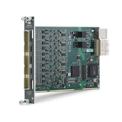
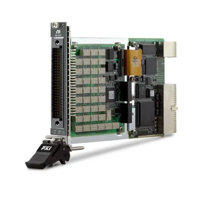
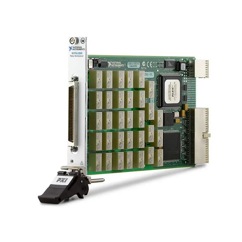
PXI-2503 48-Channel PXI Multiplexer and Matrix Switch Module
The PXI-2503 is a flexible electromechanical PXI switch module designed for automated measurement, signal routing and production test systems. Using different terminal blocks, it can operate as a 1-wire, 2-wire or 4-wire multiplexer or as a 2-wire matrix.
The module supports switching up to 60 VDC or 30 VAC, 1 A per channel and 30 W per channel. Its low thermal electromotive force, 10 MHz typical bandwidth and programmable 1,024-step scan list make it suitable for precision measurements, data acquisition, sensor testing and high-throughput automated test equipment.
Key Features of the PXI-2503
- 48-channel PXI multiplexer switch module
- Configurable multiplexer and matrix topologies
- 1-wire, 2-wire and 4-wire switching modes
- Up to 60 VDC or 30 VAC switching voltage
- 1 A maximum switching and carry current per channel
- 30 W maximum DC switching power per channel
- 10 MHz or greater typical bandwidth
- Less than 2 µV differential thermal EMF
- Less than 1 Ω initial DC path resistance
- 100 channels/s typical maximum scan rate
- 1,024-step deterministic scan list
- Nonlatching electromechanical relays
- Gold-clad silver-alloy relay contacts
- PXI hardware trigger support
- 68-pin male SCSI front-panel connector
- PXI hybrid-slot compatibility
- NI-SWITCH and NI Switch Executive support
PXI-2503 Technical Specifications
| Product Model | PXI-2503 |
|---|---|
| Part Number | 777697-01 |
| Product Type | PXI multiplexer and matrix switch module |
| Advertised Channel Count | 48 channels |
| Supported Wire Modes | 1-wire, 2-wire and 4-wire |
| Multiplexer Topologies | 64 × 1, 48 × 1, 24 × 1, dual 12 × 1, quad 6 × 1 and 12 × 1, depending on wire mode and accessory |
| Matrix Topology | 2-wire 4 × 6 matrix |
| Maximum Switching Voltage | 60 VDC or 30 VAC |
| Maximum Switching Current | 1 A per channel |
| Maximum Carry Current | 1 A per channel |
| Maximum Switching Power | 30 W per channel |
| Minimum Switch Load | 10 µA at 10 mV |
| Initial DC Path Resistance | Less than 1 Ω |
| Differential Thermal EMF | Less than 2 µV |
| Typical Bandwidth | 10 MHz or greater with 50 Ω termination |
| Maximum Scan Rate | 100 channels/s typical |
| Typical Relay Operate Time | 3 ms at 20°C |
| Maximum Relay Operate Time | 5 ms at 20°C |
| Typical Relay Release Time | 1.5 ms at 20°C |
| Maximum Relay Release Time | 5 ms at 20°C |
| Mechanical Relay Life | 5 × 10⁷ cycles expected |
| Electrical Relay Life | 2 × 10⁵ cycles expected at maximum load |
| Relay Type | Electromechanical, nonlatching |
| Relay Contact Material | Gold-clad silver alloy |
| I/O Connector | 68-pin male SCSI |
| Bus Interface | PXI hybrid |
| Module Format | 3U, one-slot PXI/cPCI module |
| Dimensions | 21.6 × 2.0 × 13.0 cm |
| Weight | 228 g |
| Operating Temperature | 0°C to 50°C |
| Software Support | NI-SWITCH and NI Switch Executive |
PXI-2503 Part Number and Accessories
| Item | Part Number | Description |
|---|---|---|
| PXI-2503 | 777697-01 | 48-channel PXI multiplexer and matrix switch module |
| TB-2605 | 777878-01 | Multiplexing terminal block and analog-bus plug kit |
| TB-2606 | 777879-01 | Terminal block for configuring the module as a 2-wire 4 × 6 matrix |
| TBX-68 | 777141-01 | 68-pin male SCSI remote connector block |
| CB-68LP | 777145-01 | Low-cost unshielded 68-pin I/O connector block |
| SH68-68-S Cable | 185262-01 | 1 m shielded 68-pin switch cable |
| SH68-68-S Cable | 185262-02 | 2 m shielded 68-pin switch cable |
| SH68-68-S Cable | 185262-05 | 5 m shielded 68-pin switch cable |
The PXI-2503 topology depends on the selected terminal block and software configuration. Use the TB-2605 for multiplexer configurations or the TB-2606 for the 2-wire 4 × 6 matrix configuration. Confirm the required topology, cable length and terminal arrangement before ordering.
Configurable Multiplexer Architecture
The PXI-2503 can connect many input channels to a common measurement instrument. This allows a digital multimeter, digitizer, data acquisition device or other instrument to measure multiple test points without requiring a separate instrument for every signal.
Depending on the selected wire mode, the module can switch individual conductors or groups of two or four conductors together. This flexibility allows the same PXI module to support single-ended voltage measurements, differential measurements, resistance measurements and other automated test configurations.
1-Wire Multiplexer Operation
In a 1-wire multiplexer configuration, one conductor from each signal is switched to a common connection. The PXI-2503 supports 1-wire multiplexer topologies including 48 × 1 and, where the applicable configuration is used, 64 × 1.
One-wire switching is useful when all signals share a common ground or return path. It provides the highest channel density but does not independently switch the signal return conductor.
2-Wire Multiplexer Operation
The module supports a 2-wire 24 × 1 multiplexer, dual 12 × 1 multiplexers or quad 6 × 1 multiplexers. Each selected channel switches two conductors simultaneously, making this mode appropriate for differential signals and measurements requiring an isolated return path.
Multiple-bank configurations allow separate instruments or measurement groups to operate through the same switch module. The correct terminal-block wiring and NI-SWITCH topology must be selected before connecting the device under test.
4-Wire Multiplexer Operation
The 4-wire 12 × 1 configuration switches four conductors for each selected channel. It is especially useful for four-wire resistance measurements in which separate source and sense connections help eliminate errors caused by cable and lead resistance.
Four-wire switching can also be used for devices that require paired differential stimulus and measurement paths. Because four conductors are assigned to every channel, this configuration provides fewer measurement channels than the 1-wire and 2-wire modes.
2-Wire 4 × 6 Matrix Configuration
Using the appropriate TB-2606 terminal block, the PXI-2503 can be configured as a 2-wire 4 × 6 matrix. A matrix allows multiple row and column connections to be established instead of limiting operation to one selected input connected to a common output.
This configuration is useful for flexible instrument-to-device routing, component characterization and automated test fixtures that require multiple possible connections between sources, instruments and test points.
60 VDC and 1 A Switching
The PXI-2503 can switch signals up to 60 VDC or 30 VAC and currents up to 1 A per channel. The maximum switching power is 30 W per channel, so voltage, current and power limits must all be observed simultaneously.
Switching inductive or capacitive loads can expose the relay contacts to voltage transients or inrush current. External suppression, current limiting or protection may be necessary when the connected load produces conditions beyond the module’s ratings.
Low Thermal EMF for Precision Measurements
The module provides less than 2 µV of differential thermal EMF. Low thermal offset helps reduce measurement error when routing low-level DC voltage, thermocouple and resistance signals.
For the best low-level measurement performance, use suitable shielded cables, minimize temperature gradients and keep high-current wiring separated from sensitive measurement paths. The thermal characteristics of cables, connectors and terminal blocks must also be considered.
Low Path Resistance
Initial DC path resistance is specified at less than 1 Ω. This value includes relay contact resistance and internal trace resistance.
Path resistance can affect voltage-drop and resistance-measurement accuracy. For precision applications, characterize the complete switch, cable and fixture path or use compensation techniques supported by the measurement system.
10 MHz Typical Bandwidth
The PXI-2503 provides a typical bandwidth of at least 10 MHz with 50 Ω termination. This supports DC and moderate-frequency signal routing in automated test and data acquisition applications.
Actual system bandwidth depends on topology, cable length, source and load impedance, fixture construction and the number of connected channels. Short shielded cables and controlled signal-path layout help preserve high-frequency performance.
Deterministic Scanning
The PXI-2503 supports a 1,024-step scan list for deterministic channel sequencing. A scan list defines the order in which switch connections are made, allowing the module to coordinate channel selection with automated measurements.
The typical maximum scan rate is 100 channels per second. Total test throughput also depends on relay settling time, measurement aperture, instrument triggering and the stabilization requirements of the signal or device under test.
PXI Hardware Triggering
Input and output triggers can be routed through PXI trigger lines 0 through 7 or the front-panel trigger connection. Hardware triggering allows switch operations to be synchronized with digital multimeters, digitizers, data acquisition modules and other PXI instruments.
Hardware-based synchronization reduces the timing uncertainty associated with software-controlled sequencing and is useful for repeatable production tests and tightly coordinated measurement systems.
Nonlatching Electromechanical Relays
The PXI-2503 uses nonlatching electromechanical relays with gold-clad silver-alloy contacts. Electromechanical switching supports signal types that may not be suitable for semiconductor switches and provides physical contact isolation when a route is open.
The relays return to their default state when power is removed. Relay life depends on the switched load, voltage, current, switching frequency and load characteristics.
Relay-Life Considerations
The expected mechanical relay life is 50 million cycles, while expected electrical life at maximum load is 200,000 cycles. Switching low-level signals generally places less electrical stress on the contacts than switching maximum-rated loads.
Applications with frequent switching should monitor relay usage and distribute high-activity routes when possible. Contact resistance that increases rapidly can indicate that a relay is approaching the end of its useful electrical life.
Typical PXI-2503 Applications
- Automated voltage and resistance measurements
- Digital multimeter channel expansion
- Production functional testing
- Printed circuit board testing
- Sensor and transducer measurement
- Thermocouple signal routing
- Four-wire resistance measurement
- Differential signal multiplexing
- Data acquisition channel selection
- Component characterization
- Instrument-to-DUT matrix routing
- Design verification and reliability testing
- Laboratory automation
Digital Multimeter Channel Expansion
The PXI-2503 can expand the number of measurement points accessible to a PXI digital multimeter. Test software selects a switch channel, allows the signal path to settle and then commands the DMM to acquire a measurement.
This arrangement reduces instrument count while allowing voltage, resistance and other measurements to be collected from multiple points. Four-wire configurations are particularly useful for accurate low-resistance measurements.
Sensor and Data Acquisition Systems
The module can route signals from multiple sensors to a shared measurement device. Its low thermal EMF helps preserve the accuracy of low-level sensor signals when the complete cabling and terminal system is designed appropriately.
When routing thermocouples or other temperature-sensitive signals, consider connector materials, cold-junction compensation, thermal gradients and the settling time required after channel changes.
Production Test Applications
In production test systems, the PXI-2503 can automatically connect measurement equipment to different test points on a device or fixture. Its programmable scan list allows repeatable sequences to run without manual cable changes.
Hardware triggering can coordinate relay operations with the measurement instrument, while NI Switch Executive can organize physical connections into readable, reusable route names.
NI-SWITCH Software Support
The PXI-2503 is controlled through the NI-SWITCH instrument driver. NI-SWITCH provides functions for initializing the module, selecting a topology, connecting and disconnecting channels, defining scan lists and configuring triggers.
The driver supports LabVIEW, LabWindows/CVI and compatible text-based programming environments. Software applications should use the exact channel names and topology defined for the selected terminal block.
NI Switch Executive Integration
NI Switch Executive allows engineers to define signal routes using meaningful aliases and route-group names. This can simplify systems containing multiple switching modules, measurement instruments and test fixtures.
Named routes reduce the need to manage every physical relay connection directly in application code. They can also make test sequences easier to review, troubleshoot and maintain.
PXI Hybrid-Slot Integration
The PXI-2503 is a one-slot 3U PXI module with a PXI hybrid bus connector. It can be installed in a compatible PXI or PXI Express hybrid slot and used alongside DMMs, digitizers, power supplies, DAQ modules and other modular instruments.
Before installation, verify the chassis slot type, controller compatibility, cooling capacity and required NI-SWITCH version. Turn off chassis power before installing or removing the module.
PXI-2503 Troubleshooting
The PXI-2503 is not detected in NI MAX
Confirm that the module is fully seated in a compatible PXI or PXI Express hybrid slot. Check chassis power, controller communication and the installed NI-SWITCH driver, then rescan the system in NI Measurement & Automation Explorer.
A requested channel cannot be connected
Verify that the NI-SWITCH topology matches the installed terminal block. Channel names and permitted routes change between 1-wire, 2-wire, 4-wire and matrix configurations.
Measurements show excessive resistance
Inspect the relay path, cable, terminal block and fixture wiring. The measured resistance includes every connection in the signal path. Four-wire measurement can reduce the effect of lead resistance when supported by the test configuration.
Low-level measurements are unstable
Allow sufficient settling time after switching. Check shielding, grounding, cable movement, temperature gradients and nearby high-current circuits. Use low-thermal connections where microvolt-level accuracy is required.
The scan rate is lower than expected
Review the measurement aperture, trigger configuration, relay settling time and device-under-test stabilization requirements. The complete test cycle normally takes longer than the relay channel-change time alone.
Relay operation becomes intermittent
Check the relay operation count, switched load and contact resistance. High current, excessive switching power and inductive transients can shorten electrical relay life.
The matrix configuration is unavailable
Confirm that the required TB-2606 matrix terminal block is installed and that the 2-wire 4 × 6 matrix topology is selected in NI-SWITCH or NI MAX.
PXI-2503 Comparison with Similar Switch Modules
| Model | Primary Configuration | Best Suited For |
|---|---|---|
| PXI-2501 | Configurable multiplexer and matrix switching | Existing PXI systems requiring related 250x switching architecture |
| PXI-2503 | 48-channel, 1-, 2- or 4-wire multiplexer; 4 × 6 matrix | Flexible low-voltage precision measurement routing |
| PXI-2527 | High-density multiplexer with multiple wire modes | Applications requiring additional channel density |
| PXI-2529 | Configurable multiplexer and matrix module | Larger matrix and multiplexer configurations |
| PXI-2530B | High-density configurable multiplexer and matrix | Systems requiring more channels and topology options |
PXI-2503 vs PXI-2530B
The PXI-2503 provides a compact 48-channel architecture with 1-wire, 2-wire, 4-wire and 4 × 6 matrix configurations. The PXI-2530B is intended for applications requiring higher channel density and a broader range of multiplexer and matrix configurations.
Choose the PXI-2503 when its available topology and 68-pin connectivity fit an existing test system. Consider the PXI-2530B when additional channels or larger matrix arrangements are required.
Recommended Related Products
- PXI-2501 Multiplexer and Matrix Switch Module
- PXI-2527 High-Density Multiplexer Switch Module
- PXI-2529 Multiplexer and Matrix Switch Module
- PXI-2530B High-Density Multiplexer and Matrix Module
- PXIe-4080 Digital Multimeter
- View More NI PXI and PXI Express Modules
Selecting the Right PXI Switch Module
Choose the PXI-2503 when the application requires a configurable multiplexer, support for 1-wire through 4-wire measurements, low thermal EMF and switching up to 60 VDC or 1 A. It is particularly useful for precision measurement systems that need several topology options from one PXI module.
Consider a higher-density multiplexer when the test fixture contains more channels than the PXI-2503 can accommodate. Select a dedicated matrix module when simultaneous instrument-to-DUT routing is more important than sequential multiplexed measurements.
Why Choose the PXI-2503?
- Supports multiple multiplexer and matrix topologies
- Provides 1-wire, 2-wire and 4-wire switching
- Handles signals up to 60 VDC and 1 A
- Offers low thermal EMF for precision measurements
- Provides at least 10 MHz typical bandwidth
- Supports deterministic 1,024-step scan lists
- Integrates with PXI hardware triggers
- Uses interchangeable terminal-block accessories
- Supports NI-SWITCH and NI Switch Executive
Frequently Asked Questions
What is the PXI-2503?
The PXI-2503 is a configurable electromechanical PXI multiplexer and matrix switch module for automated measurements and signal routing.
How many channels does the PXI-2503 provide?
NI describes the PXI-2503 as a 48-channel module. Its available channel count and routing arrangement depend on the selected wire mode, topology and terminal block.
Which multiplexer configurations are supported?
Supported configurations include 1-wire 64 × 1 and 48 × 1, 2-wire 24 × 1, dual 12 × 1 and quad 6 × 1, and a 4-wire 12 × 1 multiplexer.
Can the PXI-2503 operate as a matrix?
Yes. It supports a 2-wire 4 × 6 matrix configuration when used with the appropriate TB-2606 terminal block.
What is the maximum switching voltage?
The maximum switching voltage is 60 VDC or 30 VAC between channels or between a channel and ground.
What is the maximum switching current?
The PXI-2503 supports a maximum switching or carry current of 1 A per channel.
What is the maximum switching power?
The maximum switching power is 30 W per channel. Voltage, current and switching-power limits must all be observed.
What is the bandwidth of the PXI-2503?
The typical bandwidth is at least 10 MHz with 50 Ω termination.
Which terminal block is used for multiplexing?
The TB-2605, part number 777878-01, provides multiplexer connectivity and an analog-bus plug kit.
Which terminal block is used for matrix switching?
The TB-2606, part number 777879-01, is used for the 2-wire 4 × 6 matrix configuration.
Which software controls the PXI-2503?
The module is controlled through NI-SWITCH and can be integrated into named-route systems using NI Switch Executive.
What is the PXI-2503 part number?
The standard configured product part number is 777697-01.
Request a Quote for the PXI-2503
Contact us for current availability, lead time and project pricing for the PXI-2503 48-Channel PXI Multiplexer and Matrix Switch Module. We can also help identify compatible TB-2605 or TB-2606 terminal blocks, SH68-68-S cables, PXI chassis and related NI switch modules for your test system.















