






Quick Answer: PXIe, short for PXI Express, is a modular test and measurement platform that combines the mechanical format, synchronization features, and software ecosystem of PXI with the high-speed PCI Express communication bus. A PXIe system normally consists of a chassis, a system controller, and one or more measurement or control modules. It is widely used when an application needs high channel density, deterministic triggering, precise synchronization, and faster data transfer than conventional PXI can provide.
What Does PXIe Mean?
PXIe stands for PCI eXtensions for Instrumentation Express. It is the PCI Express-based generation of the PXI modular instrumentation standard. Instead of placing every instrument in a separate enclosure, PXIe lets engineers install multiple instruments as modules inside one chassis and operate them as a coordinated system.
The platform retains the features that made PXI useful for automated testing, including a rugged Eurocard mechanical format, shared power and cooling, dedicated clocks, hardware trigger lines, and software-based instrument control. Its main advancement is the use of PCI Express links in the chassis backplane, which substantially increases the data bandwidth available between modules and the controller.
Important distinction: PXIe is not a single instrument or connector. It is a complete system architecture. Performance depends on the combined capabilities of the chassis, controller, backplane, modules, drivers, and application software.
How Does a PXIe System Work?
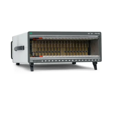
A PXIe system centralizes instruments inside a common chassis. The controller runs the operating system and test software, the backplane carries PCI Express data and synchronization signals, and the modules perform functions such as digitizing analog signals, generating waveforms, switching channels, communicating with devices, or controlling external hardware.
PXIe Chassis
Provides slots, power, cooling, PCI Express data paths, clocks, and trigger resources for the complete system.
System Controller
Runs the test application and communicates with the installed modules through the backplane.
PXIe Modules
Perform the actual measurement, generation, switching, communication, or control functions.
Software and Drivers
Configure instruments, acquire data, coordinate timing, automate procedures, and record results.
When a test begins, the controller configures the modules through PCI Express. Chassis clocks and trigger buses coordinate when each module starts or samples. Measurement data then travels across the backplane to the controller for processing, display, storage, or network transfer.
PXI vs PXIe: What Is the Difference?
| Feature | PXI | PXIe |
|---|---|---|
| Primary data bus | Parallel PCI | Serial PCI Express |
| Typical data throughput | Suitable for many traditional automated tests | Designed for high-rate and data-intensive measurements |
| Backplane topology | Shared PCI bus segments | Point-to-point PCIe links connected through switches |
| Timing and triggering | PXI clocks and trigger buses | Retains PXI resources and adds enhanced synchronization options |
| Module compatibility | PXI peripheral modules | PXIe modules; hybrid slots may also accept many PXI modules |
| Best fit | Legacy systems and moderate-bandwidth applications | RF, high-speed digitizing, vision, streaming, and modern mixed-instrument systems |
PXIe does not make conventional PXI obsolete. Many digital I/O, switch, DMM, relay, and industrial communication applications do not require extreme bandwidth. The right choice depends on module availability, existing assets, data rate, synchronization requirements, and lifecycle plans. For a broader introduction to the original platform, see What Is PXI?
Why Is PCI Express Important in PXIe?
PCI Express uses point-to-point serial links rather than a shared parallel bus. A PXIe backplane routes these links through one or more PCIe switches, allowing multiple modules to communicate with the controller at high speed. Depending on the chassis and slot, a module may receive a link with one, four, eight, or more PCIe lanes, and the link generation also affects its theoretical throughput.
However, the lane count printed in a specification is only one part of the system. Real application throughput may also be limited by the module itself, a backplane switch, the controller link, processor performance, memory, storage speed, driver behavior, or simultaneous traffic from other modules.
Practical Bandwidth Rule
Map the complete data path from each module to its final destination. Compare the required sustained data rate—not only the peak rate—with the bandwidth of the slot, shared backplane links, controller, memory, and storage device. Leave headroom for protocol overhead and concurrent module traffic.
For a closer look at link routing and shared resources, read PXI Backplane Explained.
Understanding PXIe Slot Types
Not every physical slot accepts every module. Before purchasing equipment, confirm both the mechanical connector and the electrical bus support listed in the chassis and module manuals.
| Slot Type | Purpose | Compatibility Notes |
|---|---|---|
| System controller slot | Connects an embedded controller or a remote-control interface to the backplane | Usually located at the left side of the chassis and is not a normal peripheral slot |
| PXIe peripheral slot | Supports PXIe peripheral modules through PCI Express | Does not automatically support a conventional PXI module |
| PXIe hybrid peripheral slot | Supports PXIe modules and compatible PXI modules | PXI module connector style and voltage compatibility must still be checked |
| PXIe system timing slot | Supports specialized timing and synchronization modules | Can generally accept suitable peripheral modules when not used for timing, subject to chassis documentation |
Do not judge compatibility by card size alone. A module may physically fit but still be unsupported because of the connector, bus type, required slot bandwidth, power demand, cooling direction, operating system, or driver version.
Embedded vs Remote PXIe Controllers
Every PXIe chassis requires a system controller connection. This can be provided by an embedded controller installed in the chassis or by a remote-control interface linked to an external desktop, workstation, or server.
| Controller Type | Advantages | Considerations |
|---|---|---|
| Embedded controller | Compact, self-contained, easier system integration, no external host required | CPU, storage, and upgrade options are tied to the controller format |
| Remote controller | Uses a separate computer with flexible CPU, GPU, storage, and maintenance options | Requires a compatible host interface, cable, operating system, and supported connection topology |
Select the controller by workload rather than processor name alone. Consider the number of instruments, expected streaming rate, real-time processing, software environment, storage volume, network traffic, cybersecurity policy, and required operating-system support. See How to Choose a PXI Controller for a detailed checklist.
What Types of PXIe Modules Are Available?
PXIe supports a broad range of modular instruments and interfaces. A system can mix several functions within one chassis as long as slot, software, power, cooling, and synchronization requirements are satisfied.
Analog Measurement
Digitizers, oscilloscopes, dynamic signal acquisition modules, data acquisition devices, and digital multimeters.
Signal Generation
Arbitrary waveform generators, function generators, source measure units, and programmable power instruments.
RF and Wireless Test
Vector signal analyzers, vector signal generators, transceivers, frequency references, and RF switching.
Digital and Protocol Test
Digital pattern instruments, FPGA modules, serial interfaces, avionics buses, automotive networks, and Ethernet test devices.
Switching and Multiplexing
Relay matrices, multiplexers, RF switches, fault insertion units, and signal-routing modules.
Timing and Synchronization
Clock generation, timing distribution, GPS-disciplined references, and system synchronization modules.
Start system design with the signal and measurement requirements, then choose compatible PXI and PXIe modules. Choosing the chassis first can create unnecessary slot, bandwidth, or timing constraints later.
PXIe Timing and Synchronization
High data throughput is only one reason to use PXIe. The chassis also provides shared timing resources that allow multiple modules to operate as one coordinated measurement system.
- Reference clocks give instruments a shared frequency reference.
- Trigger buses distribute start, stop, event, and handshake signals between slots.
- Star trigger resources provide dedicated paths designed to reduce slot-to-slot skew.
- Differential star resources support higher-performance clock and trigger distribution in PXIe systems.
- System timing modules can improve clock accuracy, synchronization, and coordination across multiple chassis.
Shared clocks do not guarantee that every module will sample at exactly the same instant. Instrument architecture, trigger latency, cable delay, module calibration, clock routing, and driver configuration can all affect alignment. Review PXI Trigger Bus Explained and the PXI Timing and Synchronization Guide when phase alignment or low skew is critical.
Key Benefits of PXIe
High Data Bandwidth
PCI Express links support rapid transfer from high-speed digitizers, RF instruments, cameras, and other streaming devices.
Precise Coordination
Backplane clocks and hardware triggers help instruments start, sample, and respond with predictable timing.
High Channel Density
Multiple instruments share one enclosure, power system, cooling system, controller, and software environment.
Flexible System Design
Modules can be combined or replaced as test requirements change, subject to compatibility and lifecycle support.
Automated Test Integration
Standard drivers and programming APIs support repeatable sequences, reporting, and production deployment.
Multi-Vendor Ecosystem
The open standard allows compatible chassis, controllers, and instruments from multiple vendors to be integrated.
Limitations and Design Challenges
PXIe is powerful, but it is not automatically the best platform for every measurement. A successful system requires attention to several practical constraints.
- Initial cost: A chassis, controller, software, and multiple modules may cost more than a simple benchtop instrument.
- Thermal planning: High-performance modules may require substantial airflow and cannot always be installed in any slot combination.
- Bandwidth sharing: Several modules may share a PCIe switch or controller uplink even when individual slots have fast links.
- Software compatibility: Drivers, operating systems, firmware, and application environments must support the complete hardware set.
- Signal conditioning: Sensors may still require external isolation, attenuation, amplification, excitation, or terminal accessories.
- Lifecycle management: Long-term systems need plans for calibration, spares, controller replacement, and software version control.
Common PXIe Applications
| Application | Why PXIe Is Used |
|---|---|
| Semiconductor validation and production test | Parallel measurements, precise timing, rapid data movement, and high instrument density |
| Wireless and RF test | Wideband signal generation and analysis with synchronized multi-channel operation |
| Automotive electronics | Mixed analog, digital, bus communication, switching, and fault-insertion functions |
| Aerospace and defense | Deterministic triggering, protocol interfaces, modular instrumentation, and hardware-in-the-loop integration |
| High-speed data acquisition | Sustained streaming from multiple channels to memory or storage |
| Research and physics | Accurate clock distribution and coordinated acquisition across many instruments |
| Production functional test | Repeatable automation, compact rack space, switching, and scalable test coverage |
How to Estimate PXIe Data Requirements
For a digitizer, a basic raw data-rate estimate is:
Data rate = number of channels × sample rate × bytes per sample
For example, four channels sampling at 100 MS/s with two bytes per sample produce a raw rate of approximately 800 MB/s before transport overhead, metadata, processing, or file-system effects. If several modules stream simultaneously, calculate their combined sustained rate and identify where their PCIe paths merge.
Some modules process or decimate data onboard, so the transferred rate may be lower than the converter rate. Other applications acquire short records rather than stream continuously. Use the actual acquisition mode and duty cycle when sizing the system.
Are PXI and PXIe Modules Compatible?
Compatibility is possible, but it is not universal. A PXIe hybrid slot is designed to accept PXIe peripheral modules and many compatible conventional PXI modules. A PXIe-only peripheral slot generally lacks the connector required by a conventional PXI module. A conventional PXI chassis cannot provide a PCI Express link to a PXIe module.
Before mixing generations, verify all of the following:
- Chassis slot type and connector compatibility
- Module keying and supported signaling voltage
- Required PCIe lane width and generation
- Power consumption and cooling requirements
- Driver and operating-system support
- Timing, triggering, and clock-routing requirements
- Vendor restrictions or validated system configurations
How to Choose a PXIe System
- Define the signals. List channel count, voltage, current, frequency, bandwidth, impedance, isolation, accuracy, and connector requirements.
- Select the modules. Choose instruments that meet the measurement and generation requirements, including accessories and signal conditioning.
- Calculate data flow. Estimate sustained and peak rates for every module, especially when multiple devices operate simultaneously.
- Define synchronization. Identify which instruments must share clocks, triggers, timestamps, phase, or deterministic response.
- Choose the chassis. Confirm slot count, slot types, PCIe topology, bandwidth, cooling, power, rack size, and acoustic limits.
- Choose the controller. Size CPU, RAM, storage, ports, operating system, and host link for the actual workload.
- Verify software support. Check drivers, development environment, firmware, licenses, and long-term version policy.
- Plan for expansion. Reserve appropriate slots, bandwidth, power, and cooling rather than counting empty slots alone.
- Validate the configuration. Build a representative test using the highest data rate and most demanding timing scenario before deployment.
For step-by-step purchasing guidance, see How to Choose a PXI System, How to Choose a PXI Chassis, and How to Choose PXI Modules.
PXIe vs CompactDAQ
CompactDAQ and PXIe are both modular, but they target different priorities. CompactDAQ is often a practical choice for portable or distributed sensor measurements, especially when moderate data rates and straightforward signal conditioning are more important than backplane bandwidth. PXIe is generally better when the system needs high-speed streaming, RF instruments, high channel density, tight hardware synchronization, or a broad mix of automated test functions.
The best platform is determined by the application, not by which one has the higher specification. Read CompactDAQ vs PXI for a direct comparison.
Frequently Asked Questions About PXIe
Is PXIe the same as PCIe?
No. PCIe is the computer communication bus. PXIe is an instrumentation platform that uses PCIe while adding a chassis format, power, cooling, clocks, triggers, and system specifications.
Can a PXIe chassis operate without a controller?
No. It needs either an embedded controller or a compatible remote-control interface connected to an external computer.
Can PXI modules be installed in a PXIe chassis?
Many can be installed in compatible hybrid slots, but connector, voltage, software, and chassis support must be verified for each module.
Does every PXIe slot have the same bandwidth?
No. Lane width, PCIe generation, switch topology, and shared links can differ by slot and chassis model.
Does PXIe guarantee synchronized measurements?
No. It provides synchronization resources, but the modules and software must be configured correctly, and instrument-specific delays may need compensation.
Is PXIe suitable for real-time testing?
Yes, when combined with supported real-time controllers, operating systems, FPGA hardware, and deterministic application architecture.
Can PXIe systems use modules from different manufacturers?
Often yes, because PXIe is an open standard. Driver compatibility, timing integration, support responsibility, and validated configurations still require review.
How many PXIe slots are required?
Count the controller and all required modules, then reserve the correct slot types and enough bandwidth, power, and cooling for future expansion.
Final Recommendation
PXIe is best understood as a synchronized, high-bandwidth modular test platform—not simply a faster version of a conventional instrument bus. Its value comes from combining PCI Express data transfer with shared timing, dense instrumentation, standardized mechanics, and software automation.
Begin with the signals, measurements, data rates, and timing relationships required by the application. Then select the modules and verify that the chassis, controller, backplane topology, software, cooling, and power system can support them together. For critical projects, test the proposed configuration under representative peak-load conditions before purchasing or deploying the complete system.
Categories
Latest Articles
Products on Sale


Need Help Choosing a Product?
Contact our sales team for product selection, pricing, availability and lead-time information.
sales@pxisource.com