






Quick Answer: A PXI backplane is the electrical and communication infrastructure inside a PXI chassis. It connects the controller and instrument modules, distributes power, carries PCI or PCI Express data, and provides shared clocks and trigger signals for synchronized measurements. Traditional PXI backplanes use a parallel PCI architecture, while PXI Express backplanes add high-speed point-to-point PCI Express links, a 100 MHz differential reference clock, and advanced differential star-trigger resources.
What Is a PXI Backplane?
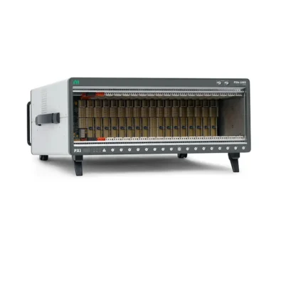
The PXI backplane is the internal circuit-board assembly located behind the slots of a PXI or PXIe chassis. When a controller and instrument modules are inserted into the chassis, their rear connectors mate with connectors on the backplane. These connections create the communication, timing, triggering, and power-distribution paths required by the complete PXI system.
It is easy to think of a backplane as a passive board that simply joins modules together. In practice, it defines much of the system architecture. The backplane determines which module types can be installed, how data reaches the controller, how much bandwidth is available, which timing signals are distributed, and how accurately multiple instruments can operate together.
For this reason, selecting a PXI chassis is not only a question of slot count. Engineers must also evaluate the backplane generation, slot type, PCI Express lane allocation, available bandwidth, timing architecture, cooling capacity, and module compatibility.
What Does the PXI Backplane Do?
Data CommunicationThe backplane carries commands, configuration data, measurement records, and streamed waveforms between the system controller and installed modules.
Power DistributionIt supplies the standardized power rails required by controllers and peripheral modules, subject to the chassis power budget and per-slot limits.
Clock DistributionCommon reference clocks help instruments derive timing from the same source and reduce long-term drift between modules.
Trigger RoutingShared trigger lines and star-trigger connections allow one device or timing module to coordinate operations across multiple slots.
The backplane also supports module identification, system enumeration, and slot-specific resources. In a PXIe chassis, active PCI Express switches may be used to route point-to-point serial links between the system controller slot and peripheral slots.
The Main Layers of a PXI Backplane
Mechanical and Connector Interface
PXI is based on the Eurocard mechanical format associated with CompactPCI. The chassis provides standardized slot dimensions, card guides, front-panel alignment, and rear connectors. This mechanical standardization allows compatible modules from different manufacturers to fit into a common modular platform.
The physical connector layout matters because PXI, PXIe, hybrid-compatible, and system timing slots do not all expose the same electrical interfaces. A module that appears mechanically similar may still be electrically incompatible with a particular slot.
Power Distribution
The chassis power supply feeds the backplane, which distributes the required voltage rails to the installed modules. Available total power and cooling are important when the chassis contains high-performance digitizers, RF instruments, FPGA modules, source measure units, or other power-intensive devices.
System designers should verify three separate values: total chassis power, the power available to each slot, and the airflow or cooling capacity at the expected operating temperature. An unused slot does not automatically guarantee that sufficient power and cooling are available for any module.
Data Bus
In a traditional PXI chassis, the backplane extends the parallel PCI bus across the controller and peripheral slots. In PXI Express, the backplane uses PCI Express serial links. These links are organized into lanes, and multiple lanes can be combined into wider connections such as x4, x8, or x16, depending on the chassis and slot architecture.
PCI Express connections are point-to-point rather than one shared parallel bus. A PXIe backplane commonly includes one or more switches that connect the controller to different peripheral slots. The actual bandwidth available to a module depends on its link width and generation, as well as shared switch links and the controller connection.
Timing and Triggering
Timing and triggering resources distinguish PXI from a general-purpose computer expansion system. The backplane allows instruments to share reference clocks, triggers, and synchronization signals without external cables. This makes PXI especially useful for automated test, multichannel acquisition, RF testing, electronic validation, and mixed-instrument systems.
Traditional PXI Backplane Architecture
A conventional PXI backplane extends the 32-bit or 64-bit PCI architecture and adds instrumentation-specific signals. These signals include the PXI trigger bus, the 10 MHz system reference clock, the PXI star trigger, and local-bus connections between adjacent slots.
Parallel PCI Data Bus
The original PXI data bus is based on parallel PCI. Multiple devices communicate through a shared bus architecture. PCI bridges may divide a larger chassis into bus segments so that additional slots can be supported.
This architecture provides sufficient performance for many digital multimeters, switches, industrial I/O interfaces, relay modules, serial interfaces, and moderate-speed data acquisition devices. However, shared parallel buses provide substantially less streaming bandwidth than modern PCI Express links.
PXI 10 MHz Reference Clock
The PXI_CLK10 signal supplies a common 10 MHz reference clock to the peripheral slots. Compatible instruments can use this clock as a frequency reference or derive their own clocks from it. Sharing a common reference helps prevent independent oscillators from drifting apart during long acquisitions or generation tasks.
A reference clock does not automatically cause every device to sample at the same instant. The instruments must support the selected synchronization method, and the application normally also requires appropriate trigger routing and driver configuration.
PXI Trigger Bus
The PXI trigger bus provides eight shared trigger lines, commonly identified as PXI_TRIG<0..7>. Modules can use these lines to route start, stop, pause, reference, handshake, or other application-specific trigger events across the chassis.
Because these lines are connected as a shared bus, their propagation delay and loading differ from dedicated point-to-point star connections. They are highly flexible for general triggering but may not provide the tightest possible slot-to-slot skew.
PXI Star Trigger
The PXI star trigger provides dedicated routes from the system timing slot to the peripheral slots. Unlike a shared trigger bus, each destination receives a separate connection. This topology reduces differences in propagation delay and is useful when multiple instruments must respond to a trigger with tighter alignment.
A compatible timing module installed in the system timing slot normally drives the star-trigger routes. The exact implementation and supported slots depend on the chassis.
Local Bus
PXI local-bus signals connect adjacent peripheral slots. Manufacturers may use these connections for private high-speed data transfer, analog signal routing, sideband communication, or specialized multi-module functions. Local-bus behavior is product-specific, so compatibility must be confirmed in the documentation for the chassis and modules.
PXI Express Backplane Architecture
PXI Express, commonly abbreviated as PXIe, extends the PXI platform with PCI Express technology while retaining instrumentation-focused clocks and triggers. The result is a modular architecture suitable for high-speed digitizers, RF signal analyzers and generators, FPGA instruments, high-channel-count acquisition, and data-intensive automated test.
Point-to-Point PCI Express Links
Each PXIe peripheral connection uses one or more serial PCI Express lanes. Because the links are point-to-point, one module does not share the same electrical bus with every other module in the way devices share a traditional parallel PCI bus. Backplane switches aggregate and route traffic between the controller and the peripheral slots.
This architecture increases bandwidth, improves scalability, and allows chassis designers to assign different lane widths to different slots. It also creates an important selection consideration: two PXIe slots in the same chassis may not have identical maximum bandwidth.
PCI Express Lanes and Switches
A lane contains separate transmit and receive differential pairs, enabling full-duplex communication. Wider links combine multiple lanes. The chassis specification may describe slot links and system links using terms such as x1, x4, x8, or x16.
Theoretical lane speed alone does not equal sustained measurement throughput. Real performance is also influenced by PCI Express generation, protocol overhead, switch topology, upstream link width, controller capability, memory performance, driver design, and simultaneous traffic from other modules.
100 MHz Differential Reference Clock
PXIe adds a 100 MHz differential clock called PXIe_CLK100. The backplane distributes this clock independently to compatible peripheral slots using low-skew point-to-point connections. Differential signaling improves noise immunity and supports more precise synchronization than a heavily loaded shared line.
PXI Express also retains the 10 MHz PXI reference clock for backward-compatible timing. This allows systems to support instruments designed around either the traditional PXI timing resource or the newer PXIe reference clock, subject to module and slot compatibility.
PXIe Synchronization Clock
PXIe_SYNC100 provides a synchronization signal associated with the 100 MHz reference-clock architecture. Compatible devices can use it to align internal timing operations and to coordinate the reliable transfer of synchronous triggers.
Differential Star Triggers
PXI Express adds dedicated differential star-trigger connections, commonly identified as PXIe_DSTAR. The architecture supports separate point-to-point routes between the system timing slot and each compatible peripheral slot. Depending on the connection, signals can travel from the timing slot to a peripheral module, from a peripheral module back to the timing slot, or in both directions as defined by the platform specification.
Differential star triggers provide high signal integrity and low slot-to-slot skew. They are valuable for phase-coherent acquisition, synchronized waveform generation, RF test, radar validation, and other applications that require precise timing across multiple instruments.
PXI vs. PXIe Backplane Comparison
| Feature | Traditional PXI Backplane | PXI Express Backplane |
|---|---|---|
| Primary data architecture | Parallel PCI | Point-to-point PCI Express |
| Data routing | Shared bus segments and bridges | Serial lanes and PCIe switches |
| Typical use | Moderate-bandwidth instruments, switching, DMM, industrial interfaces | Digitizers, RF, FPGA, high-speed streaming, large data systems |
| Reference clocks | 10 MHz PXI clock | Retains 10 MHz and adds 100 MHz differential clock |
| General trigger lines | Eight PXI trigger lines | Retains compatible PXI trigger resources |
| Star triggering | Single-ended PXI star | PXI star support plus differential star resources in compatible slots |
| Bandwidth planning | Bus and segment bandwidth | Per-slot lane width, PCIe generation, switch and upstream bandwidth |
Important: PXIe is not automatically necessary for every application. A switch module or digital multimeter may generate little data and operate effectively in a traditional PXI system. PXIe becomes especially valuable when instruments continuously stream large data volumes or require advanced differential synchronization.
PXI Backplane Slot Types Explained
System Controller Slot
The system controller slot is normally located at the left side of the chassis and is reserved for an embedded PXI controller or a remote-control interface. It connects the host processing system to the backplane data architecture and manages enumeration of installed devices.
PXI Peripheral Slot
A PXI peripheral slot supports compatible traditional PXI modules using the parallel PCI interface and PXI timing resources. It does not automatically accept a PXIe-only module because the required PCI Express connector and electrical connections may be absent.
PXIe Peripheral Slot
A PXIe peripheral slot provides PCI Express connectivity for PXIe modules. A PXI module cannot normally be inserted into a PXIe-only peripheral slot because the connector arrangement is different.
Hybrid-Compatible Slot
A hybrid-compatible slot is designed to accept compatible PXIe modules and PXI hybrid-compatible modules. It improves flexibility during migration from older PXI hardware to newer PXIe platforms. However, some older PXI modules use connector features that prevent installation in a hybrid slot. Always check the chassis and module documentation.
System Timing Slot
The system timing slot provides dedicated access to the chassis timing and star-trigger resources. A compatible timing and synchronization module can distribute higher-accuracy clocks and triggers to other modules. In many chassis it can also operate as a general peripheral slot when no timing module is required, but this must be confirmed for the specific chassis.
| Slot Type | Primary Purpose | Typical Module | Key Check |
|---|---|---|---|
| System controller | Controls the chassis and data bus | Embedded controller or remote interface | Controller generation and chassis support |
| PXI peripheral | Parallel PCI instrumentation | PXI DMM, switch, DAQ, interface | PXI connector and bus compatibility |
| PXIe peripheral | PCI Express instrumentation | PXIe digitizer, RF or FPGA module | Link width, generation, and slot type |
| Hybrid-compatible | Mixed PXI/PXIe deployment | PXIe or compatible hybrid PXI module | Legacy PXI connector restrictions |
| System timing | Clock and trigger distribution | Timing and synchronization module | Star-trigger and clock capabilities |
How Data Moves Through a PXIe Backplane
When a PXIe instrument acquires data, its onboard ADC, FPGA, or digital processing circuitry first produces measurement records. The module then transfers those records through its PCI Express endpoint and slot link. A backplane switch routes the traffic toward the system controller link, and the controller moves the data into system memory for processing, display, analysis, or storage.
- The instrument measures or generates a signal.
- Onboard logic buffers or processes the data.
- The module transfers data through its PCIe lane connection.
- A backplane switch routes traffic through an upstream link.
- The controller receives the data and places it in memory.
- Driver and application software process or store the results.
If several high-speed modules stream simultaneously, they may share an upstream switch connection. Therefore, total system throughput must be evaluated from the complete block diagram of the chassis, not by multiplying the theoretical maximum rate of each occupied slot.
Backplane Bandwidth: Per-Slot vs. System Bandwidth
Per-Slot Bandwidth
Per-slot bandwidth describes the maximum connection between an individual peripheral slot and its backplane switch or controller path. It is influenced by PCI Express generation and lane width.
System Bandwidth
System bandwidth describes the aggregate data capability of the chassis backplane architecture. It considers the combined links between switches and the system controller. Marketing specifications may state a high aggregate value, but an application can still encounter a bottleneck in one branch of the topology.
Sustained Application Throughput
Sustained throughput is the practical rate achieved by the complete system. It is affected by the controller, CPU, memory, storage device, operating system, driver, data block size, and concurrent traffic. Recording high-speed data to disk may be limited by storage performance even when the backplane has additional capacity.
Bandwidth-planning method:
- Calculate the expected data rate of each module.
- Identify which modules share each backplane switch.
- Compare their combined rate with the switch's upstream connection.
- Check the controller link and memory bandwidth.
- Verify storage speed if data will be continuously recorded.
- Allow margin for overhead, bursts, and future expansion.
Why Backplane Timing Matters
Two modules can begin acquisition from the same software command and still fail to produce precisely time-aligned data. Software commands pass through the operating system and driver stack, so their latency is not deterministic enough for tight synchronization.
Backplane clocks and hardware triggers provide a more repeatable timing relationship. A common reference clock keeps device timebases frequency-locked, while a hardware trigger defines when an event begins. Star-trigger routes reduce slot-dependent propagation differences when tighter alignment is required.
For the best result, the installed modules must support the same timing strategy. Chassis resources alone cannot compensate for incompatible device timing engines, analog filter group delay, different ADC architectures, or incorrect software configuration.
PXI Backplane Compatibility Considerations
Compatibility requires more than a matching module width. Before installing a module, verify all of the following:
- Whether the module is PXI, PXIe, or hybrid-compatible
- The exact slot type and connector arrangement
- Chassis and controller generation
- Required PCI or PCI Express link width
- Backplane timing and trigger resources
- Module power consumption and chassis power budget
- Cooling and airflow requirements
- Driver, operating-system, and application-software support
- Local-bus or star-trigger requirements
Physical fit is not proof of compatibility: Never force a module into a slot. Similar front-panel dimensions do not guarantee that rear connectors, signaling standards, power requirements, or software support are compatible.
How to Select the Right PXI Backplane and Chassis
List Every Required Module
Start with the exact model number of each controller and instrument. Classify every module as PXI, PXIe, or hybrid-compatible and note its slot width, power consumption, and bandwidth demand.
Map Modules to Slot Types
Compare the module list with the chassis slot map. Reserve the controller position and system timing slot where required. Confirm that enough compatible peripheral or hybrid slots remain for all instruments.
Calculate Data Throughput
Estimate the sustained rate from each digitizer, RF instrument, or FPGA module. For acquisition, a basic uncompressed estimate is channel count multiplied by sample rate and bytes per sample, plus protocol and application overhead.
Review the Backplane Block Diagram
The block diagram shows lane widths, switches, and upstream connections. It is the most useful document for identifying shared bottlenecks and deciding where high-throughput modules should be installed.
Define Synchronization Accuracy
Determine whether the application needs only a common start event, frequency alignment, sample-level synchronization, phase coherence, or synchronization across multiple chassis. This decision determines whether general trigger lines are sufficient or whether a timing module and star-trigger resources are needed.
Allow for Expansion
Select enough spare compatible slots, power, cooling, and bandwidth for expected upgrades. Leaving physical slots empty is useful only if the remaining system resources can support the future instruments.
Common Applications of PXI Backplanes
- Automated functional test: Coordinates DMMs, switches, power supplies, digital I/O, and waveform instruments.
- High-speed data acquisition: Streams synchronized multichannel data to controller memory or storage.
- RF and wireless test: Supports high-throughput signal analyzers, generators, switches, and timing modules.
- Semiconductor test: Integrates synchronized source-measurement, digital, switching, and waveform resources.
- Aerospace and defense: Enables deterministic triggering, radar testing, hardware-in-the-loop systems, and multichannel recording.
- Research and validation: Provides modular instruments with shared timing and scalable bandwidth.
Frequently Asked Questions About PXI Backplanes
Is the PXI backplane the same as the PXI chassis?
No. The backplane is the internal electrical and communication board. The chassis includes the backplane, enclosure, power supply, cooling system, slot guides, and monitoring functions.
What is the difference between a PXI and PXIe backplane?
A PXI backplane primarily uses parallel PCI, while a PXIe backplane uses PCI Express point-to-point links and switches. PXIe also adds a 100 MHz differential reference clock and differential star-trigger resources while retaining important PXI timing features.
Can a PXI module work in a PXIe chassis?
It may work in a compatible hybrid slot, but not in every PXIe slot. Some legacy PXI modules cannot fit a hybrid-compatible connector. Verify the module and chassis compatibility documentation before installation.
Can a PXIe module work in a traditional PXI chassis?
No. A PXIe module requires PCI Express connectivity and the appropriate PXIe connector, which a traditional PXI-only backplane does not provide.
Does every PXIe slot have the same bandwidth?
No. Slot link width, PCI Express generation, switch connection, and upstream bandwidth may differ. Review the chassis backplane block diagram for the exact allocation.
What is the PXI trigger bus?
It is a set of eight shared hardware trigger lines used to route timing events among compatible modules. It is flexible for general triggering but does not provide the same point-to-point characteristics as star-trigger connections.
What is a PXI star trigger?
A star trigger uses dedicated routes from a system timing slot to peripheral slots. The matched point-to-point topology provides lower slot-to-slot skew than a shared trigger bus.
Why does PXIe include both 10 MHz and 100 MHz clocks?
The 10 MHz clock preserves compatibility with traditional PXI timing methods. The 100 MHz differential clock supports higher-performance, low-skew timing for compatible PXIe instruments.
Does higher backplane bandwidth improve every instrument?
No. It benefits modules that move large data volumes. Low-bandwidth instruments such as many DMMs, relays, switches, and serial interfaces may see little practical improvement.
Can the PXI backplane synchronize several chassis?
A single backplane synchronizes resources inside its chassis. Multiple chassis normally require external clock and trigger distribution, dedicated timing modules, or synchronization technologies such as GPS, IEEE 1588, IRIG-B, or vendor-specific links, depending on the required accuracy.
Conclusion
The PXI backplane is the foundation of a modular test system. It does much more than connect a controller to instrument modules: it distributes power, transports measurement data, supplies common reference clocks, and routes hardware triggers for coordinated operation.
Traditional PXI backplanes use parallel PCI and provide the 10 MHz reference clock, eight-line trigger bus, star trigger, and local-bus resources. PXI Express backplanes add point-to-point PCI Express links, switching, a 100 MHz differential clock, synchronization signals, and advanced differential star triggers for high-bandwidth and tightly synchronized applications.
The correct chassis should be selected by analyzing module compatibility, slot types, power, cooling, per-slot bandwidth, switch topology, controller performance, and synchronization requirements as a complete system. A careful backplane evaluation prevents compatibility problems and ensures that the test platform can deliver the required throughput and timing accuracy.
Need help selecting a PXI or PXIe chassis?
Send us your controller and module model numbers, required slot count, expected data rate, synchronization requirements, and application details. We can help identify a compatible PXI chassis and backplane architecture for your test system.
Send us your controller and module model numbers, required slot count, expected data rate, synchronization requirements, and application details. We can help identify a compatible PXI chassis and backplane architecture for your test system.
Categories
Latest Articles
Products on Sale


Need Help Choosing a Product?
Contact our sales team for product selection, pricing, availability and lead-time information.
sales@pxisource.com