






Quick Answer: The PXI Trigger Bus is a set of eight shared hardware signal lines, identified as
PXI_TRIG<0..7>, built into a PXI or PXIe chassis backplane. Compatible modules use these lines to exchange start, reference, pause, clock, synchronization, or handshaking signals without external cables. The trigger bus is flexible and suitable for many automated test systems, but applications requiring the lowest slot-to-slot skew may use PXI Star or PXIe Differential Star connections instead.What Is the PXI Trigger Bus?
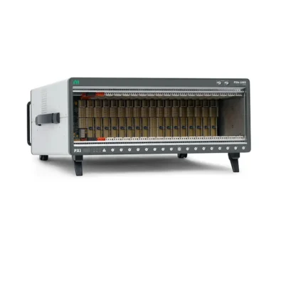
The PXI Trigger Bus is one of the instrumentation-specific features that distinguishes the PXI platform from a general-purpose PCI or PCI Express computer. It provides eight backplane signal lines that allow compatible controllers and instrument modules to communicate timing events directly through the chassis.
These lines are named PXI_TRIG0 through PXI_TRIG7, or collectively PXI_TRIG<0..7>. Each line can be assigned a role by the modules, drivers, and application software. One line might carry a start trigger from a digitizer to a waveform generator, while another carries a reference trigger, pause signal, sample clock, or device-specific handshake.
Unlike a fixed-purpose connector, the trigger bus does not define one permanent function for each line. Its strength is flexible routing. The exact signals that a module can export or import depend on its internal timing engine, driver, and terminal-routing capabilities.
Why Does PXI Need a Hardware Trigger Bus?
Software can command several instruments to start, but software execution passes through an operating system, drivers, and communication layers. The timing of those commands varies from one execution to another. That variability makes ordinary software control unsuitable when measurements must start at a predictable instant or remain aligned across multiple modules.
The trigger bus provides a hardware path. One device can generate an electrical event, and other devices can respond to that event through the backplane. This architecture reduces external cabling, improves repeatability, and supports deterministic coordination inside the chassis.
Deterministic StartA master instrument can send a hardware start event to one or more slave instruments.
Shared EventsMultiple modules can react to the same reference, pause, stop, or marker event.
Reduced CablingSignals travel through the backplane instead of separate front-panel cables.
System IntegrationDrivers can coordinate routes, reserve lines, and configure multidevice operations.
How the Eight PXI Trigger Lines Work
The eight trigger lines run along a trigger-bus segment of the chassis backplane. Compatible slots on that segment connect to the same group of lines. A module configured as the source drives a selected line, and one or more destination modules monitor the same line.
- A source module produces an internal event, such as an analog comparison or acquisition start.
- The module's timing engine routes that event to an available PXI trigger terminal.
- The selected line carries the electrical transition across the backplane segment.
- One or more destination modules receive the transition.
- Each destination uses the event to start, stop, pause, latch, or synchronize an operation.
Because the lines are shared, only one active source should drive a given trigger line at one time unless a specifically supported protocol says otherwise. Several receivers may listen to the line, but two unrelated sources attempting to drive it can cause a route conflict and unreliable behavior.
Important: A PXI chassis provides the physical trigger lines, but it does not guarantee that every module connects to every line or supports every signal type. Verify the routing table or hardware manual for each module.
Common Signals Routed Over the PXI Trigger Bus
Start Trigger
A start trigger tells a configured device when to begin an acquisition or generation operation. The device is normally armed first and then waits for the hardware edge. This is one of the most common ways to coordinate digitizers, DAQ modules, waveform generators, digital instruments, and other PXI modules.
Reference Trigger
A reference trigger identifies an event within an acquisition record. A digitizer may collect samples before and after the reference event, allowing the system to preserve pretrigger and post-trigger data. The trigger bus can distribute the same reference event to several compatible instruments.
Pause Trigger
A pause trigger temporarily controls whether an acquisition or generation task proceeds. It can be useful for gated measurements, conditional acquisition, or excluding data during an invalid process state.
Arm or Advance Trigger
Some instruments use an arm trigger to enable a later trigger stage, or an advance trigger to move through a sequence of generated waveforms, switching states, or list-mode operations. Support and naming vary between product families.
Clock or Timebase
The PXI specification permits variable-frequency clock transmission over the trigger bus. This can help modules share a timebase that is not derived from the standard 10 MHz PXI reference clock. The specification recommends PXI_TRIG7 for compatible variable-frequency clock transmission to improve interoperability.
A shared trigger line is not always the best path for a high-quality clock. Loading, reflections, propagation delay, and jitter must be considered. When available, dedicated reference clocks or differential star connections generally provide better timing performance.
Handshake and Communication Signals
Manufacturers may implement protocols that use trigger lines for ready, acknowledge, data-valid, or other intermodule handshaking. The trigger bus can also support general-purpose module-defined communication, provided the electrical and routing rules are followed.
| Signal Type | Purpose | Typical Example | Key Consideration |
|---|---|---|---|
| Start trigger | Begins a configured operation | Start several digitizers from one master | Arm destinations before generating the event |
| Reference trigger | Marks a point within acquired data | Capture samples before and after a fault | Configure record length and pretrigger samples |
| Pause trigger | Gates an active task | Acquire only while a process is valid | Check level or edge behavior |
| Clock | Shares a periodic timing signal | Distribute a custom sample timebase | Evaluate jitter, rate, and receiving support |
| Handshake | Coordinates intermodule states | Ready and acknowledge sequencing | Usually device- or driver-specific |
Asynchronous and Synchronous PXI Triggers
Asynchronous Trigger
An asynchronous trigger is not required to have a defined phase relationship with the PXI backplane reference clock. A source generates a pulse or edge, and receivers detect the event according to their own trigger circuitry. This method is simple and flexible, but different modules may recognize the event on different internal clock edges.
Asynchronous triggers work well when the application needs a common approximate start event and small timing differences are acceptable. The final synchronization accuracy depends on backplane propagation, receiver circuitry, device timebases, and internal processing.
Synchronous Trigger
A synchronous PXI trigger is generated and received in relation to the common PXI_CLK10 reference clock. Participating modules detect the trigger according to a defined reference-clock edge. This creates a more predictable timing relationship for operations derived from the same 10 MHz timebase.
Sharing only a trigger is not the same as sharing or locking clocks. If devices start together but run from independent oscillators, their sample timing can gradually drift. For long synchronized acquisitions, devices normally need a common reference clock as well as a coordinated start event.
Practical synchronization principle:
- Use a common reference clock to control long-term frequency alignment.
- Use a hardware trigger to define when acquisition or generation begins.
- Use a synchronous protocol or star route when lower skew is required.
- Confirm that every participating module supports the selected method.
PXI Trigger Bus vs. PXI Star Trigger
The trigger bus and star trigger both distribute timing events, but their electrical topologies are different.
The PXI Trigger Bus is shared. Each line connects multiple slots on a segment, providing flexible one-to-many routing. This flexibility also means the line is affected by the electrical loading and physical positions of connected modules.
PXI Star uses an individual point-to-point route between the system timing slot and each supported peripheral slot. Trace lengths are closely matched to reduce differences in propagation time. A timing module installed in the designated timing slot can distribute a trigger to the other modules with tighter slot-to-slot alignment.
PXI Trigger Bus vs. PXIe Differential Star
PXI Express retains the eight traditional PXI trigger lines and also adds differential star-trigger resources known as PXIe_DSTAR. Differential signaling improves noise immunity and signal integrity, while dedicated point-to-point connections provide lower skew than a shared trigger bus.
PXIe Differential Star is especially useful for high-speed digitizers, RF instruments, phase-coherent systems, FPGA modules, radar testing, and applications requiring precise module-to-module timing. It normally requires compatible modules and access to the PXIe system timing slot.
| Resource | Topology | Main Advantage | Typical Use |
|---|---|---|---|
| PXI Trigger Bus | Eight shared lines per trigger segment | Flexible routing and broad compatibility | Start, pause, reference, handshake, general triggers |
| PXI Star | Dedicated single-ended routes from timing slot | Lower slot-to-slot skew | Tighter multidevice synchronization |
| PXIe Differential Star | Dedicated differential point-to-point routes | Best signal integrity and precise timing | RF, high-speed acquisition, FPGA, phase alignment |
| External cabling | Front-panel or chassis connections | Connects unsupported devices or separate chassis | Cross-chassis or mixed-platform triggering |
Trigger Propagation Delay and Skew
Propagation delay is the time required for an electrical trigger to travel from its source to a destination. Skew is the difference in arrival time between multiple destinations. These parameters matter when several modules must capture the same event with tight time correlation.
On a shared trigger bus, propagation depends on the position of the source and receivers, bus length, loading, drivers, and signal integrity. Receivers may also add different internal delays before applying the event to their measurement engines.
Consequently, the trigger line can coordinate when operations begin without guaranteeing that analog samples from different modules are perfectly aligned. For precision synchronization, consider the complete timing chain:
- Trigger source detection delay
- Source-module output delay
- Backplane routing and propagation delay
- Destination input and resynchronization delay
- Sample-clock phase and timebase accuracy
- ADC or digital-filter group delay
- Driver and task configuration
Trigger Bus Segments in Larger Chassis
A large PXI or PXIe chassis may divide the trigger bus into multiple segments to preserve signal integrity and limit electrical loading. Each segment has its own eight trigger lines. The lines on separate segments are not necessarily connected by default.
When a source and destination are located on different segments, the chassis may provide programmable bidirectional buffers that route a selected trigger line between segments. The route usually connects the same numbered line—for example, PXI_TRIG2 on one segment to PXI_TRIG2 on another.
Cross-segment routing can introduce additional delay. The direction of the route must also be configured correctly so that the signal travels away from the source segment. On supported NI systems, trigger-segment routing can be configured through Measurement & Automation Explorer or appropriate platform services.
Common mistake: Two modules can be installed in the same chassis but still belong to different trigger-bus segments. If an apparently valid route does not work, check the chassis backplane diagram and trigger-segment configuration.
Trigger Routing and Line Reservation
Drivers commonly reserve a trigger line when a task is committed or started. Reservation prevents another operation from configuring a conflicting source on the same physical line. Automatic routing can select an available terminal when a valid path exists, while explicit routing allows the engineer to choose a particular line.
A typical terminal name may resemble /Dev1/PXI_Trig0, although exact names depend on the device, chassis identification, driver, and programming environment. The leading slash and device context can matter when specifying routes.
After stopping a task, a previously exported route may remain reserved until the task is uncommitted, cleared, or reconfigured. If another task reports that the terminal is already in use, release the original reservation before creating the new route.
Automatic Routing
Automatic routing reduces configuration work when the driver understands the installed chassis and device topology. It can select available lines and avoid many conflicts. Correct chassis identification is important; otherwise, the software may not know which backplane routes exist.
Explicit Routing
Explicit routing is useful when the system design reserves particular lines, when several instruments must share one known trigger, or when cross-segment routing requires a defined path. The engineer must make sure that the selected terminal is supported by both source and destination.
Typical PXI Trigger Bus Configuration
Consider a system with one master digitizer and two slave modules. The goal is to begin all three acquisitions from the master's analog trigger.
- Configure channels, sample rates, record lengths, and input ranges on all modules.
- Configure the master to detect the required analog event.
- Export the master's start trigger to an available line such as
PXI_TRIG0. - Configure both slaves to use
PXI_TRIG0as their digital start-trigger source. - Commit or start the slave tasks first so they are armed and waiting.
- Start or arm the master task.
- Apply the signal that generates the master trigger.
- Read the acquired records and verify time alignment.
Starting the master before the slaves can cause the slaves to miss a short trigger pulse. A reliable sequence arms every receiver before enabling the source event.
Using the PXI Trigger Bus with NI-DAQmx and LabVIEW
NI-DAQmx-supported modules can often import or export start triggers, reference triggers, sample clocks, and other internal signals. In LabVIEW, applications may use trigger configuration VIs, timing VIs, export-signal functions, terminal properties, or multidevice tasks depending on the hardware.
The exact route is device-dependent. A DAQ module may export an analog input start trigger, while another instrument family may expose different terminals through its own driver. Never assume that the same route syntax or signal set applies to all PXI instruments.
Before programming, verify that the chassis and module positions are correctly identified in NI MAX. Software needs an accurate topology to determine valid backplane paths and perform automatic routing.
Common PXI Trigger Bus Problems
No Registered Trigger Lines Between Devices
This error can occur when the software does not recognize the chassis topology, the modules are assigned to the wrong chassis, or no valid path exists between the selected terminals. Confirm chassis identification, slot assignments, and driver support.
Trigger Line Already Reserved
Another task or instrument may already own the line. Stop and clear the previous task, remove its exported route, or select a different trigger line. Ensure that only one source drives the line.
Slave Module Never Starts
The slave may not be armed before the trigger arrives, may be configured for the wrong edge, or may be listening to a different terminal. Check trigger polarity, source name, task order, and whether the source actually exports the event.
Works Within One Segment but Not Another
Configure trigger routing across the chassis segments. Confirm the route direction and make sure the selected line is available on each segment.
Measurements Start Together but Drift
A common trigger aligns the initial event but does not lock independent timebases. Configure a shared reference clock or an appropriate reference-clock synchronization method.
Unexpected Skew Between Modules
Shared trigger-bus propagation, different input circuitry, independent sample clocks, ADC architecture, and filter delay can all contribute. Use a common reference, synchronous triggering, or star-trigger resources where supported.
| Symptom | Likely Cause | Recommended Check |
|---|---|---|
| Route cannot be created | Unsupported terminal or incorrect topology | Check device routing table and chassis identification |
| Resource reserved | Another task owns the line | Stop, uncommit, clear, or reconfigure the original task |
| Receiver misses trigger | Receiver was armed too late | Start slave tasks before the source task |
| Cross-segment failure | Segment buffers are not routed | Configure trigger routing in the chassis settings |
| Long-term timing drift | Independent device clocks | Share or lock to a common reference clock |
| Excessive module skew | Shared-bus and device timing delays | Use PXI Star or PXIe Differential Star if supported |
Best Practices for Reliable Trigger Routing
- Create a trigger-line allocation table before programming a complex system.
- Use one clearly defined source for each active shared line.
- Arm receiving tasks before enabling the source trigger.
- Use a common reference clock for long or continuous synchronized acquisition.
- Keep clocks on dedicated clock resources when possible.
- Check the chassis diagram for trigger segments and programmable buffers.
- Confirm trigger polarity, pulse width, and voltage compatibility.
- Release reserved routes when tasks stop or system modes change.
- Use star-trigger resources when the application requires tighter alignment.
- Measure actual end-to-end skew for critical systems instead of relying only on nominal routing specifications.
How to Choose the Right Triggering Method
Use the PXI Trigger Bus When
- You need flexible one-to-many trigger distribution.
- The modules support a common PXI trigger terminal.
- Moderate slot-to-slot skew is acceptable.
- You need start, pause, reference, or handshake signals.
- You want to minimize front-panel cabling.
Use PXI Star When
- Lower slot-to-slot skew is required.
- A compatible system timing module is available.
- Participating modules support the PXI Star terminal.
Use PXIe Differential Star When
- The system requires precise, high-integrity synchronization.
- You are coordinating high-speed digitizers, RF, or FPGA instruments.
- The chassis and modules support the required DSTAR connections.
Use External Trigger Cabling When
- Devices are installed in separate chassis.
- A module does not connect to the required backplane line.
- An external instrument must participate in the timing system.
- The application requires a specialized electrical interface.
Frequently Asked Questions About the PXI Trigger Bus
How many trigger lines does PXI provide?
The standard PXI Trigger Bus provides eight shared lines, numbered PXI_TRIG0 through PXI_TRIG7.
Are the eight lines assigned fixed functions?
No. Their functions are configured by the instruments, drivers, and application. Supported routes depend on the installed hardware.
Can one trigger start multiple PXI modules?
Yes. One source can drive a selected trigger line and multiple compatible destination modules can receive it. The receivers should be armed before the event occurs.
Can two modules drive the same trigger line?
Normally, only one active source should drive a shared line. Two sources can create contention or route-reservation errors unless a specific supported protocol explicitly permits the arrangement.
Is the trigger bus available in PXIe chassis?
Yes. PXI Express retains the traditional eight-line trigger bus while adding advanced timing resources such as a 100 MHz differential clock and differential star triggers.
Does the PXI Trigger Bus synchronize sample clocks?
It can carry compatible clock signals, but a trigger alone does not synchronize independent sample clocks. For long-term alignment, use a shared reference clock or supported synchronization method.
What is the difference between PXI_TRIG and PXI_STAR?
PXI_TRIG lines are shared across multiple slots. PXI_STAR uses dedicated, closely matched point-to-point routes from the system timing slot, providing lower slot-to-slot skew.
Why should PXI_TRIG7 sometimes be used for clock transmission?
The PXI specification recommends line 7 for compatible variable-frequency clock transmission to improve interoperability between clock sources and receivers.
Why does a trigger work in some slots but not others?
The modules may be on separate trigger-bus segments, a route buffer may not be configured, or one module may not connect to the selected line. Check the chassis and module documentation.
Can trigger signals be shared between multiple chassis?
Not through one internal backplane bus alone. Multiple chassis require supported external trigger connections, timing modules, cabling, or a chassis synchronization architecture.
Conclusion
The PXI Trigger Bus is a flexible eight-line hardware network built into the chassis backplane. It allows controllers and instrument modules to exchange start, reference, pause, clock, handshake, and other timing events without separate front-panel cables.
Its shared-bus topology makes it convenient for general triggering and one-to-many event distribution. However, accurate synchronization depends on more than selecting a trigger line. Engineers must consider reference clocks, propagation delay, device timing engines, trigger-bus segments, signal reservation, receiver arming order, and ADC or filter delays.
For systems requiring tighter slot-to-slot alignment, PXI Star or PXIe Differential Star resources may be more suitable. The best architecture is determined by the installed modules, required timing accuracy, data-acquisition duration, chassis topology, and software environment.
Need help configuring a PXI triggering system?
Send us your chassis, controller and module model numbers, required trigger source, synchronization accuracy, sample rate and application details. We can help identify compatible PXI hardware and an appropriate trigger-routing architecture.
Send us your chassis, controller and module model numbers, required trigger source, synchronization accuracy, sample rate and application details. We can help identify compatible PXI hardware and an appropriate trigger-routing architecture.
Categories
Latest Articles
Products on Sale


Need Help Choosing a Product?
Contact our sales team for product selection, pricing, availability and lead-time information.
sales@pxisource.com