






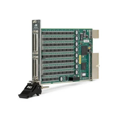
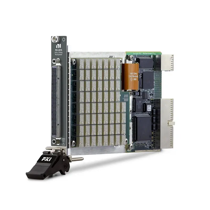
PXI-2575 High-Density Multiplexer Switch Module
The PXI-2575 is a high-density PXI multiplexer switch module designed to route hundreds of signals to measurement instruments or source units. It supports a 196×1 one-wire topology and selectable 98×1 or 95×1 two-wire topologies.
With switching ratings up to 100 V and 1 A, a scan rate of 140 cycles per second and onboard relay-count tracking, the PXI-2575 is suitable for automated data acquisition, production testing and high-channel-count signal-routing systems.
Key Features of the PXI-2575
- 196×1 one-wire multiplexer topology
- 98×1 two-wire multiplexer topology
- 95×1 two-wire multiplexer topology
- Maximum switching voltage of 100 V
- Maximum switching and carry current of 1 A
- Maximum switching power of 60 W or 62.5 VA per channel
- Greater than 20 MHz bandwidth in one-wire mode
- Greater than 8 MHz bandwidth in two-wire mode
- 140-cycle-per-second scan rate
- Electromechanical latching relays
- 1 ms typical relay operate time
- Onboard relay-count tracking
- Hardware triggering and deterministic scanning
- PXI Hybrid slot compatibility
PXI-2575 Technical Specifications
| Product Model | PXI-2575 |
|---|---|
| Part Number | 778572-75 |
| Product Type | PXI Multiplexer Switch Module |
| One-Wire Topology | 196×1 multiplexer |
| Two-Wire Topologies | 98×1 and 95×1 multiplexers |
| Maximum Switching Voltage | 100 V channel-to-channel |
| Channel-to-Ground Rating | 100 V, Measurement Category I |
| Maximum Switching Current | 1 A |
| Maximum Carry Current | 1 A |
| Maximum Switching Power | 60 W or 62.5 VA per channel |
| One-Wire Bandwidth | Greater than 20 MHz |
| Two-Wire Bandwidth | Greater than 8 MHz |
| Initial DC Path Resistance | Less than 0.5 Ω |
| DC Isolation Resistance | Greater than 1 GΩ, typical at 25°C |
| Differential Thermal EMF | Less than 12 µV |
| Scan Rate | 140 cycles/s |
| Typical Relay Operate Time | 1 ms |
| Maximum Relay Operate Time | 3.4 ms |
| Relay Type | Electromechanical latching |
| Mechanical Relay Life | 1 × 10⁸ cycles |
| Front Connector | 200-position LFH |
| Bus Interface | PXI Hybrid |
Part Number and Available Topologies
| Part Number | Topology | Channels | Recommended Use |
|---|---|---|---|
| 778572-75 | One-wire 196×1 | 196 | Single-ended signal routing |
| 778572-75 | Two-wire 98×1 | 98 pairs | Differential and paired-signal routing |
| 778572-75 | Two-wire 95×1 | 95 pairs | Improved cable signal performance |
196×1 One-Wire Multiplexer Mode
In one-wire mode, the PXI-2575 routes any of 196 single-ended input channels to a common connection. This topology provides maximum channel density for applications in which every signal shares a common reference or return path.
One-wire mode offers a bandwidth greater than 20 MHz with a 50 Ω termination. It is suitable for scanning voltage signals, device test points and other single-conductor measurement paths.
98×1 Two-Wire Multiplexer Mode
The 98×1 topology pairs two signal conductors and switches both conductors together. This configuration is appropriate for differential signals and applications that require the signal and return connections to be routed simultaneously.
When standard LFH200 breakout cables are used, channels 95, 96 and 97 are not routed as twisted pairs and can have lower high-frequency performance than the other channels.
95×1 Two-Wire Multiplexer Mode
The 95×1 topology excludes the final three channel pairs that do not use twisted-pair routing in compatible breakout cables. This provides more consistent signal performance across the available two-wire channels.
Choose the 95×1 topology when signal integrity is more important than using the three additional channel pairs. Choose the 98×1 topology when maximum differential channel count is required and the reduced performance of the final channels is acceptable.
High-Channel-Count Signal Routing
The PXI-2575 allows one measurement instrument to acquire signals from as many as 196 single-ended channels or 98 paired channels. It can also route a source signal from the common connection to a selected device under test.
This architecture can reduce the number of digital multimeters, digitizers, source units and other instruments required in a test system. Only the selected signal path is connected to the common terminal during conventional multiplexer operation.
Voltage, Current and Power Ratings
The PXI-2575 supports signals up to 100 V channel-to-channel and 100 V channel-to-ground in Measurement Category I applications. Maximum switching and carry current is 1 A.
The switching power on any channel must not exceed 60 W or 62.5 VA. Voltage, current and power are separate limits, and all three requirements must be satisfied simultaneously.
The module must not be connected directly to Measurement Category II, III or IV circuits or to mains distribution circuits such as 115 VAC or 230 VAC wall outlets.
Electromechanical Latching Relays
The PXI-2575 uses electromechanical latching relays. A latching relay maintains its selected state without requiring continuous coil power, which can reduce heat generation after switching.
Relay operation takes approximately 1 ms under typical conditions and no more than 3.4 ms under specified conditions. Some applications may require additional settling time before an accurate measurement can be made.
Relay Monitoring and Preventive Maintenance
Onboard relay counting records the operation count of the switching relays. Test software can retrieve this information to identify frequently used paths and plan preventive maintenance.
The expected mechanical relay life is up to 100 million cycles under specified conditions. Electrical life can be shorter and depends on switched voltage, current, load type and transient suppression.
Hardware Triggering and Scanning
The PXI-2575 supports deterministic scanning with PXI hardware triggers. A predefined scan list can be loaded to the module and advanced without issuing a separate software command for every connection.
Hardware scanning reduces controller overhead and allows relay changes to be coordinated with a digital multimeter, digitizer or other PXI measurement instrument.
Typical PXI-2575 Applications
- High-channel-count data acquisition
- Automated voltage scanning
- Electronic component testing
- Semiconductor production testing
- Battery cell monitoring
- Cable and wiring-harness testing
- Environmental chamber monitoring
- Industrial sensor acquisition
- Functional circuit-board testing
- Device-under-test signal routing
- Automated production testing
- Research and laboratory measurement systems
Software and Driver Support
The PXI-2575 can be controlled using the NI-SWITCH driver. NI-SWITCH provides topology configuration, channel routing, scan-list execution, hardware triggering and relay-count monitoring.
NI Switch Executive can simplify larger switching systems by allowing engineers to create channel aliases, define routes and detect routing conflicts. The module can also be controlled through LabVIEW, LabWindows/CVI, C/C++, C# and supported Python environments.
Cables and Terminal Accessories
The PXI-2575 uses a high-density 200-position LFH front connector. Compatible connection accessories include:
- LFH200-to-four-50-pin D-SUB switch cable, 1 m, part number 779038-02
- LFH200-to-four-50-pin D-SUB switch cable with channel-to-channel twisted pairs, part number 779038-03
- LFH200-to-bare-wire switch cable, 2 m, part number 779038-01
- TBX-50 screw-terminal block, part number 779305-01
Confirm the cable voltage rating, topology and channel-pair arrangement before purchase. The available LFH200 cables referenced for this module are rated for signals up to 60 VDC, which is lower than the module’s 100 V maximum rating.
PXI Chassis and System Integration
The PXI-2575 uses a PXI Hybrid-compatible bus connector. It can be installed in supported PXI peripheral slots or compatible hybrid slots, subject to chassis and controller compatibility.
Suitable chassis options include the PXIe-1092, PXIe-1085 and other NI PXI chassis that provide an appropriate hybrid-compatible slot.
Installation and Troubleshooting
Module Is Not Detected
Confirm that the PXI-2575 is fully installed in a compatible PXI or hybrid slot. Verify chassis communication and install the required NI-SWITCH driver before checking the module in NI Measurement & Automation Explorer.
Unexpected Channels Are Connected
Verify the selected topology before creating routes. Channel names and pairings differ among the 196×1, 98×1 and 95×1 operating modes.
Two-Wire Measurements Are Noisy
Use a cable with twisted channel pairs and consider the 95×1 topology. In the 98×1 topology, the final three channel pairs can have lower high-frequency performance with standard breakout cables.
Measurements Require Additional Settling Time
Add a delay after each relay operation to allow the relay, cable and connected measurement instrument to settle. High-impedance sources and capacitive loads may require more settling time than the relay operate-time specification alone.
Path Resistance Is Too High
Inspect the cable, terminal block and external wiring, then review the relay operation count. Initial module path resistance is below 0.5 Ω, but contact resistance rises as a relay reaches the end of its electrical life.
The Cable Cannot Support the Required Voltage
Apply the lowest rating among the module, cable, terminal block and external wiring. Do not apply the module’s complete 100 V rating through a cable specified for only 60 V.
PXI-2575 Comparison with Similar Multiplexer Modules
| Model | Primary Configuration | Recommended Selection |
|---|---|---|
| PXI-2575 | 196×1 one-wire or up to 98×1 two-wire | Maximum multiplexer channel density in a PXI Hybrid module |
| PXIe-2575 | 196×1 one-wire or up to 98×1 two-wire | Similar functionality with a native PXI Express interface |
| PXI-2576 | Multiple configurable two-wire multiplexer banks | Applications requiring several independent multiplexers |
| PXIe-2527 | Configurable one-, two- and four-wire multiplexing | Higher-voltage or lower-channel-count switching |
| PXIe-2529 | High-density matrix switching | Systems requiring flexible row-to-column connections |
Recommended Related Products
- PXIe-2575 Multiplexer Switch Module – provides similar high-density routing with a native PXI Express interface
- PXI-2576 Multiplexer Switch Module – offers multiple independent and configurable multiplexer banks
- PXIe-2527 Multiplexer Switch Module – supports one-, two- and four-wire signal routing
- PXIe-2529 Matrix Switch Module – provides flexible high-density matrix connections
- PXIe-4081 Digital Multimeter – can be combined with the multiplexer for automated multichannel measurements
Additional compatible switching hardware is available in our NI PXI modules category.
How to Select the PXI-2575
Choose the PXI-2575 when a test system must route up to 196 single-ended signals or as many as 98 paired signals to one measurement instrument or source connection.
Before purchasing, confirm the required topology, voltage, current, switching power, bandwidth, settling time, cable arrangement and chassis compatibility. Use the 95×1 topology when consistent twisted-pair cable performance is more important than the three additional channel pairs.
Why Choose the PXI-2575?
The PXI-2575 provides exceptional multiplexer channel density, three selectable topologies and deterministic hardware scanning in one modular instrument. It can substantially reduce the number of measurement instruments and manual cable changes required by high-channel-count automated test systems.
Frequently Asked Questions
How many channels does the PXI-2575 provide?
It provides 196 channels in one-wire mode, 98 channel pairs in the complete two-wire mode or 95 channel pairs in the optimized two-wire mode.
What is the difference between the 95×1 and 98×1 topologies?
The 95×1 topology excludes three pairs that do not receive the same twisted-pair cable routing as the other channels. It can therefore provide more consistent high-frequency signal performance.
What is the maximum switching voltage?
The maximum switching voltage is 100 V channel-to-channel or channel-to-ground in Measurement Category I applications.
What is the maximum switching current?
The maximum switching and carry current is 1 A, subject to the 60 W or 62.5 VA per-channel power limit.
What is the maximum scanning speed?
The PXI-2575 supports scanning at up to 140 cycles per second.
Does the PXI-2575 track relay usage?
Yes. Onboard relay-count tracking allows maintenance software to monitor the number of operations performed by the relays.
What is the difference between PXI-2575 and PXIe-2575?
They provide the same main switching topologies and signal ratings, but the PXI-2575 uses a PXI Hybrid-compatible interface while the PXIe-2575 uses a native PXI Express interface.
What is the part number for the PXI-2575?
The standard NI part number for the PXI-2575 is 778572-75.
Request a Quote for the PXI-2575
Contact us for current availability, lead time and project pricing for the PXI-2575 High-Density Multiplexer Switch Module. We can also help identify compatible cables, terminal blocks, PXI chassis, controllers and measurement instruments.















