







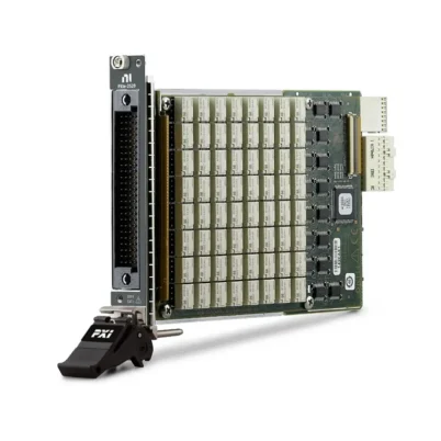
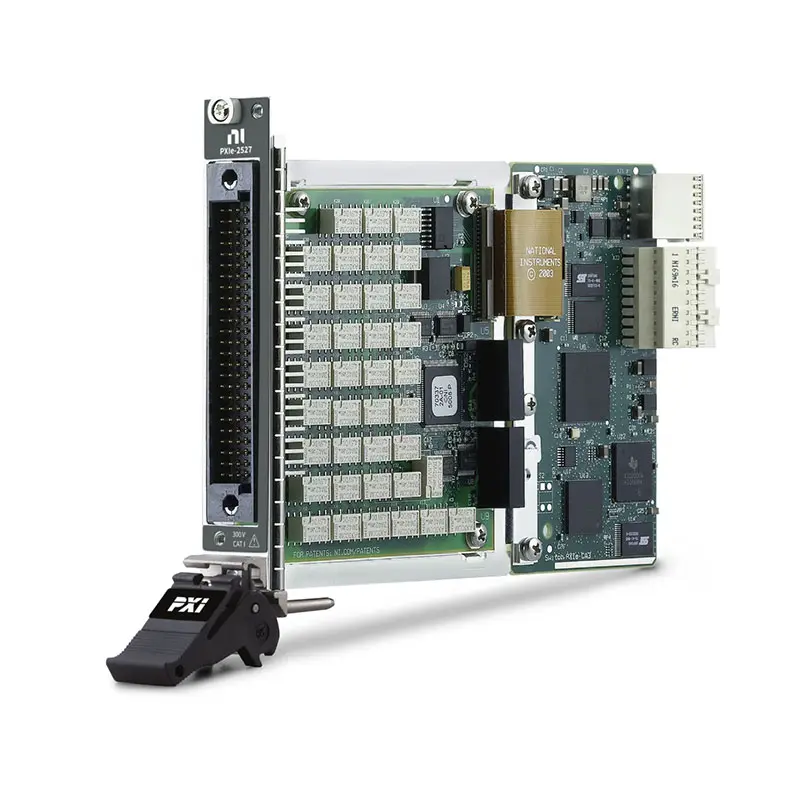
PXIe-2527 High-Voltage Multiplexer Switch Module
The PXIe-2527 is a high-voltage PXI Express multiplexer switch module designed for medium- and high-density automated test systems. It provides flexible signal routing for voltage, current, resistance, capacitance, inductance and temperature measurements.
Featuring high-power electromechanical relays, multiple multiplexer topologies and deterministic hardware triggering, the PXIe-2527 is an effective channel-expansion front end for compatible PXI digital multimeters and other measurement instruments.
Key Features of the PXIe-2527
- Maximum switching voltage of 300 V
- Maximum switching or carrying current of 2 A
- 64×1 one-wire multiplexer configuration
- 32×1 two-wire multiplexer configuration
- 16×1 four-wire multiplexer configuration
- Dual-bank multiplexer configurations
- Up to 140 relay cycles per second
- More than 30 MHz bandwidth in one-wire mode
- More than 25 MHz bandwidth in two-wire mode
- Electromechanical latching relays
- Onboard relay-count monitoring
- Deterministic hardware triggering
- Field-replaceable relays
- Native PXI Express interface
PXIe-2527 Technical Specifications
| Product Model | PXIe-2527 |
|---|---|
| Part Number | 780587-27 |
| Product Type | High-Voltage Multiplexer Switch Module |
| Bus Type | PXI Express |
| Maximum Channel Count | 64 channels |
| Single Multiplexer Topologies | 64×1 one-wire, 32×1 two-wire or 16×1 four-wire |
| Dual-Bank Topologies | Dual 32×1 one-wire or dual 16×1 two-wire |
| Maximum Switching Voltage | 300 V |
| Maximum Switching or Carry Current | 2 A |
| Minimum Switch Load | 20 mV or 1 mA |
| Maximum Scan Rate | 140 cycles/s |
| One-Wire Bandwidth | Greater than 30 MHz |
| Two-Wire Bandwidth | Greater than 25 MHz |
| Initial DC Path Resistance | Less than 1 Ω |
| Typical Relay Operate Time | 1 ms |
| Maximum Relay Operate Time | 3.4 ms |
| Relay Type | Electromechanical latching |
| Front Connector | 100-position HDI male |
| PXI Slots Required | 1 |
PXIe-2527 Part Number and Accessory
| Model | Part Number | Description |
|---|---|---|
| PXIe-2527 | 780587-27 | 64-channel, 300 V PXI Express multiplexer module |
| TB-2627 | 779358-01 | Direct-mount screw-terminal block for PXI/PXIe-2527 |
| HV6-BAN4 | 192795-0R2 | Cable for connecting multiplexer common terminals to DMM banana inputs |
Configurable Multiplexer Topologies
The PXIe-2527 can be configured in several single-bank and dual-bank topologies. This allows the same module to support different measurement methods and channel-density requirements.
- 64×1 one-wire: Provides maximum channel density for signals using a shared return path.
- 32×1 two-wire: Routes differential or signal-and-return channel pairs.
- 16×1 four-wire: Supports compensated four-wire resistance measurements.
- Dual 32×1 one-wire: Provides two independent one-wire multiplexers.
- Dual 16×1 two-wire: Provides two independent two-wire multiplexers.
The topology is selected through software and must match the physical wiring of the terminal block or custom connection assembly.
High-Voltage Signal Routing
The PXIe-2527 can switch signals up to 300 V and currents up to 2 A within its specified operating limits. It is suitable for automated systems that must route higher-voltage signals than conventional low-level multiplexer modules can accommodate.
Voltage, current and switching-power ratings are separate limits. They should not be interpreted as being simultaneously available under all conditions. The connected terminal block, cable and measurement instrument must also meet the voltage and current requirements of the application.
PXI Digital Multimeter Channel Expansion
The PXIe-2527 can expand a compatible PXI digital multimeter across multiple devices or test points. A single DMM can sequentially perform voltage, current, resistance, capacitance or inductance measurements through the multiplexer.
This arrangement reduces instrument count and system cost while maintaining software-controlled routing. The four-wire topology is particularly useful for low-resistance measurements where test-lead resistance must be compensated.
Hardware-Triggered Scanning
The PXIe-2527 accepts triggers from PXI trigger lines and provides deterministic relay operation for automated scanning. Hardware coordination between the switch and a measurement instrument can improve throughput and reduce the timing variation associated with software-controlled switching.
The module supports relay operation rates up to 140 cycles per second. Additional settling time may be necessary for certain instruments, cables, loads and measurement types.
Relay Monitoring and Maintenance
Onboard relay counting records the number of operations performed by individual relays. Engineers can use this information to schedule preventive maintenance and identify heavily used signal paths before relay degradation affects test results.
The electromechanical relays are field replaceable. Actual relay life depends on the switched voltage, current, power, load type and switching frequency.
Typical PXIe-2527 Applications
- Automated production testing
- High-channel-count voltage measurements
- Two-wire and four-wire resistance measurements
- Battery and power-system testing
- Electronic component characterization
- Environmental chamber monitoring
- Thermocouple signal scanning
- Manufacturing process monitoring
- Research and laboratory measurements
- PXI digital multimeter channel expansion
NI-SWITCH Software Support
The PXIe-2527 is controlled through the NI-SWITCH instrument driver. NI-SWITCH provides functions for topology selection, channel routing, scan-list configuration, triggering and relay-count monitoring.
NI Switch Executive can also be used to create named routes and manage larger switching systems graphically. Compatible development environments include LabVIEW, LabWindows/CVI, C and supported Microsoft programming environments.
TB-2627 Terminal Block
The TB-2627 is the recommended front-mount screw-terminal block for the PXIe-2527. It connects directly to the module and provides access to all channels required for single- or dual-bank one-wire, two-wire and four-wire multiplexer configurations.
The TB-2627 also includes a cold-junction compensation sensor that can assist with thermocouple scanning applications. The optional HV6-BAN4 cable connects the multiplexer common terminals to the banana inputs of a compatible digital multimeter.
Safety and Wiring Considerations
The TB-2627 and PXIe-2527 are intended for Measurement Category I signals. They must not be connected directly to Category II, III or IV circuits, including standard 115 V or 230 V wall-outlet power circuits.
Before applying power, verify conductor insulation, terminal-block covers, strain relief, grounding and the ratings of all connected equipment. Always use the lowest voltage, current and power rating within the complete signal path.
PXI Express Chassis Integration
The PXIe-2527 occupies one peripheral slot in a compatible PXI Express chassis. It can be combined with PXI DMMs, digitizers, source measurement units and other modular instruments to create an integrated automated test platform.
Verify chassis slot compatibility and cooling before installation. Unused slots should be fitted with filler panels to maintain proper airflow through the system.
PXIe-2527 Troubleshooting
The module is not detected by the system
Confirm that the PXIe-2527 is fully seated in a compatible PXI Express slot. Verify the chassis, controller and NI-SWITCH installation, then check the device status in NI Measurement & Automation Explorer.
The channels do not route as expected
Verify that the software-selected topology matches the physical TB-2627 wiring. Channel relationships differ between one-wire, two-wire, four-wire and dual-bank configurations.
The measured resistance is inaccurate
For low-resistance measurements, use the four-wire topology to compensate for test-lead and relay-path resistance. Allow sufficient settling time after each channel change and perform instrument compensation where applicable.
The measurements are unstable or noisy
Inspect the terminal connections, shielding and grounding. Keep signal cables away from switching power supplies, motors and other interference sources. Confirm that the switched signal remains within the specified limits.
The scan rate is lower than expected
Review the DMM aperture time, relay settling delay, trigger routing and scan-list configuration. Overall system throughput is determined by both the switch timing and the connected measurement instrument.
A relay may have reached the end of its service life
Review the onboard relay count and measure the path resistance. Relay life decreases when switching high-power or inductive loads, and additional transient suppression may be required for motors, solenoids and similar devices.
PXIe-2527 Compared with Related Multiplexer Modules
| Model | Configuration | Maximum Voltage | Best Suited For |
|---|---|---|---|
| PXIe-2527 | 64×1 one-wire, 32×1 two-wire or 16×1 four-wire | 300 V | High-voltage PXI Express measurement systems |
| PXI-2527 | 64×1 one-wire, 32×1 two-wire or 16×1 four-wire | 300 V | Legacy PXI and PXI Hybrid systems |
| PXI-2575 | 196×1 one-wire or 98×1 two-wire | 100 V | Higher-density signal routing |
| PXIe-2525 | Configurable multiplexer | 150 V | General-purpose medium-voltage switching |
| PXIe-2529 | Configurable matrix | 150 V | Flexible row-to-column matrix routing |
Recommended Related Products
- PXI-2527 Multiplexer Switch Module – The PXI version for legacy PXI and PXI Hybrid systems.
- PXIe-4081 Digital Multimeter – A high-resolution DMM for precision voltage, current and resistance measurements.
- PXIe-4080 Digital Multimeter – A versatile DMM for automated multipoint measurement systems.
- PXI-2575 Multiplexer Switch Module – A higher-density alternative for lower-voltage signals.
- PXIe-2529 Matrix Switch Module – A matrix-routing option for connecting multiple sources and loads.
- PXIe-1092 PXI Express Chassis – A chassis for modular automated test and measurement systems.
Additional switching, measurement and signal-routing products are available in the NI PXI Modules category.
Selecting the PXIe-2527
Choose the PXIe-2527 when an application requires up to 300 V signal handling, flexible one-wire through four-wire routing and native PXI Express integration. It is particularly suitable as a channel-expansion front end for a PXI digital multimeter.
Select the PXI-2527 for older PXI-based systems. If the application requires substantially more channels at a lower maximum voltage, the PXI-2575 may provide a more appropriate channel configuration.
PXIe-2527 vs PXI-2527
The PXIe-2527 and PXI-2527 provide similar switching topologies and electrical performance but use different bus interfaces and part numbers. The PXIe-2527 uses a native PXI Express interface and carries part number 780587-27. The PXI-2527 carries part number 778572-27.
Confirm the available chassis slot type before ordering. These two versions should not be treated as the same orderable product even though both are compatible with the TB-2627 terminal block.
Why Choose the PXIe-2527?
- Handles signals up to 300 V and 2 A
- Supports one-wire, two-wire and four-wire measurements
- Provides single- and dual-bank multiplexer configurations
- Expands compatible PXI DMMs across multiple test points
- Supports deterministic hardware-triggered scanning
- Tracks relay usage for preventive maintenance
- Integrates directly into PXI Express test systems
Frequently Asked Questions
What is the PXIe-2527 used for?
The PXIe-2527 routes multiple test points to a shared measurement instrument. It is commonly used to expand a PXI DMM for voltage, current, resistance and other multipoint measurements.
How many channels does the PXIe-2527 provide?
It provides up to 64 channels in a one-wire configuration. It can also operate as a 32×1 two-wire, 16×1 four-wire or dual-bank multiplexer.
What is the maximum switching voltage?
The PXIe-2527 supports switching voltages up to 300 V within its specified Measurement Category I limits.
What is the maximum switching current?
The module supports switching or carrying currents up to 2 A. The applicable voltage, current and power limits must be evaluated for the specific signal and load.
Which terminal block is compatible with the PXIe-2527?
The recommended terminal block is the TB-2627, part number 779358-01.
Can the PXIe-2527 perform four-wire resistance measurements?
Yes. Its 16×1 four-wire topology supports compensated resistance measurements using a compatible four-wire DMM.
What is the difference between PXIe-2527 and PXI-2527?
The principal difference is the bus interface. The PXIe-2527 is a native PXI Express module, while the PXI-2527 uses the PXI interface. Their orderable part numbers are also different.
What is the part number for the PXIe-2527?
The standard NI part number for the PXIe-2527 is 780587-27.
Request a Quote for the PXIe-2527
Contact us for current availability, lead time and project pricing for the PXIe-2527 High-Voltage Multiplexer Switch Module. We can also help identify compatible PXI digital multimeters, TB-2627 terminal blocks, cables and PXI Express chassis for your test system.















