






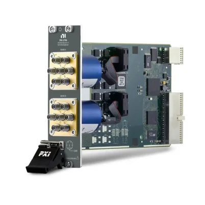
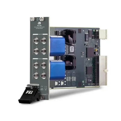

PXI-2797 40 GHz Terminated RF Multiplexer Module
The PXI-2797 is a 50 Ω, 6×1 terminated PXI RF multiplexer designed for routing RF and microwave signals at frequencies up to 40 GHz. It connects one of six input channels to a common RF port while terminating every unselected channel.
With low insertion loss, high channel isolation and electromechanical coaxial switching, the PXI-2797 is suitable for semiconductor testing, microwave component characterization, harmonic measurements and automated RF production systems.
Key Features of the PXI-2797
- Single terminated 6×1 multiplexer bank
- SP6T RF switching topology
- Frequency coverage up to 40 GHz
- 50 Ω characteristic impedance
- Electromechanical coaxial relay
- Maximum insertion loss below 1.1 dB at 40 GHz
- Maximum RF carry power of 18 W at lower frequencies
- Maximum switching voltage of 30 Vrms
- Maximum carry current of 0.6 Arms
- Internal 50 Ω termination on unselected channels
- Greater than 50 dB open-channel isolation at 40 GHz
- 5-channel-per-second recommended scan speed
- 15 ms relay operate and release time
- Hardware triggering and relay-count tracking
- PXI Hybrid bus compatibility
PXI-2797 Technical Specifications
| Product Model | PXI-2797 |
|---|---|
| Part Number | 782357-01 |
| Product Type | PXI RF Multiplexer Switch Module |
| Topology | Terminated 6×1 multiplexer |
| Relay Configuration | SP6T |
| Number of Banks | 1 |
| Number of Input Channels | 6 |
| Maximum Frequency | 40 GHz |
| Characteristic Impedance | 50 Ω |
| Relay Type | Electromechanical |
| Maximum Switching Voltage | 30 Vrms, cold switching only |
| Maximum Carry Current | 0.6 Arms per channel |
| Maximum RF Carry Power | 18 W, frequency-dependent |
| Termination Power | 1 W average per channel, 3 W total at 25°C |
| Insertion Loss at 6 GHz | Less than 0.2 dB |
| Insertion Loss at 12.4 GHz | Less than 0.4 dB |
| Insertion Loss at 18 GHz | Less than 0.5 dB |
| Insertion Loss at 26.5 GHz | Less than 0.7 dB |
| Insertion Loss at 40 GHz | Less than 1.1 dB |
| Relay Operate/Release Time | 15 ms |
| Recommended Scan Speed | 5 channels/s |
| Bus Interface | PXI Hybrid |
Part Number and Configuration
| Part Number | Topology | Frequency | Impedance | Termination |
|---|---|---|---|---|
| 782357-01 | 6×1 SP6T multiplexer | Up to 40 GHz | 50 Ω | Yes |
6×1 Microwave Multiplexer Architecture
The PXI-2797 routes one of six RF input channels to a single common connection. Only one channel can be connected to the common port at a time.
This topology allows a signal analyzer, receiver, power sensor or other RF instrument to measure signals from as many as six devices or test points without manually reconnecting microwave cables.
Terminated RF Channels
Every input channel that is not connected to the common port is internally connected to its associated 50 Ω termination. This helps prevent open-channel reflections and provides a controlled load for attached RF sources.
The internal terminators are rated for an average of 1 W per channel at 25°C, with the total termination power limited to 3 W. The terminators cannot withstand the module’s full 18 W RF carry-power rating.
Low Insertion Loss to 40 GHz
The PXI-2797 is designed to minimize attenuation across its microwave frequency range. Maximum insertion loss is specified below 0.2 dB through 6 GHz and below 1.1 dB through 40 GHz.
Low insertion loss makes the module suitable for routing weak microwave signals and high-order harmonics. System software should still compensate for switch, cable and adapter loss when accurate amplitude measurements are required.
Frequency-Dependent RF Power Handling
The maximum RF carry power depends on frequency. The PXI-2797 supports up to 18 W through 12.4 GHz, with the allowable power decreasing at higher frequencies.
| Frequency Range | Maximum RF Carry Power |
|---|---|
| Up to 12.4 GHz | 18 W |
| Above 12.4 GHz to 18 GHz | 15 W |
| Above 18 GHz to 26.5 GHz | 10 W |
| Above 26.5 GHz to 40 GHz | 5 W |
Confirm both source power and possible external amplifier gain before connecting a signal. The applicable carry-power rating must not be confused with the lower power rating of the internal termination loads.
Open-Channel Isolation
High isolation reduces signal leakage between the selected path and unselected channels. The PXI-2797 provides open-channel isolation greater than 70 dB through 6 GHz and greater than 50 dB through 40 GHz.
Actual system isolation also depends on RF cable routing, connector condition, chassis configuration and external fixture design. Keep high-level transmitter paths separated from low-level receiver paths whenever possible.
Cold-Switching Requirements
The PXI-2797 uses electromechanical microwave relays and should not switch an active RF signal. During relay movement, the selected channel can become momentarily unterminated, potentially creating reflections that may damage or destabilize some RF sources.
Disable or sufficiently reduce the RF source before changing routes. After the relay has settled, restore the required signal level and begin the measurement.
Electromechanical Relay Operation
Electromechanical coaxial relays provide low insertion loss and strong isolation across the module’s 40 GHz bandwidth. Relay operation and release take approximately 15 ms, and the recommended scanning speed is five channels per second.
The module records relay operations in nonvolatile memory. Relay-count data can support preventive maintenance and help identify channels approaching their expected mechanical operating life.
Typical PXI-2797 Applications
- 40 GHz microwave signal routing
- RF semiconductor production testing
- High-order harmonic measurements
- Microwave component characterization
- Millimeter-wave research systems
- Multiple-source signal analyzer routing
- Receiver and transmitter validation
- Aerospace and defense RF testing
- Radar subsystem testing
- Automated antenna measurements
- High-frequency calibration systems
- Laboratory microwave test systems
Software and Driver Support
The PXI-2797 is controlled using the NI-SWITCH driver. NI-SWITCH supports channel routing, disconnection, triggering, scanning and relay-count monitoring.
NI Switch Executive can simplify larger RF switching systems by allowing users to create aliases, define routes and store RF path information. The module can also be controlled through LabVIEW, LabWindows/CVI, C/C++, C# and supported Python environments.
RF Cable and Connector Considerations
Use 50 Ω microwave cables, adapters and torque-controlled connectors rated for operation to 40 GHz. Standard low-frequency SMA cables may not provide acceptable insertion loss, return loss or mode control at the upper end of the module’s frequency range.
Inspect all microwave connectors before use. Damaged center contacts, contamination and incorrect torque can permanently damage the module or significantly reduce measurement repeatability.
PXI Chassis and System Integration
The PXI-2797 uses a PXI Hybrid-compatible bus connection and requires a chassis with suitable hybrid or compatible peripheral slots. Verify the module width and adjacent slot availability when planning the system.
Compatible chassis options include the PXIe-1092, PXIe-1085 and other NI PXI chassis offering the required hybrid-compatible slots.
Installation and Troubleshooting
Module Is Not Detected
Confirm that the PXI-2797 is fully installed in a compatible PXI Hybrid slot. Check chassis communication and install the required NI-SWITCH driver before reviewing the module in NI Measurement & Automation Explorer.
Unexpectedly High Insertion Loss
Confirm that the intended channel is connected to COM. Inspect the microwave cables, adapters and connectors, and verify that every component is rated for the measurement frequency.
Signal Leakage Appears on Unselected Channels
Review the expected isolation at the operating frequency and inspect external cable routing. High-power transmit signals can couple into adjacent low-level paths outside the switch module.
An RF Source Becomes Unstable During Switching
Do not switch active RF signals. Disable or reduce the source before operating the relay because the RF path can be momentarily unterminated while the relay changes position.
Termination Becomes Overloaded
Verify the power present on every unselected channel. Each internal termination is limited to 1 W average power, and total power across all terminations must not exceed 3 W at 25°C.
Amplitude Results Differ Between Channels
Characterize each complete RF path and apply channel-specific correction data. Cable length, connector repeatability and relay-path variation can create small differences between channels.
PXI-2797 Comparison with Similar Microwave Switch Modules
| Model | Topology | Maximum Frequency | Termination | Recommended Selection |
|---|---|---|---|---|
| PXI-2797 | Single 6×1 multiplexer | 40 GHz | Yes | Terminated 40 GHz SP6T routing |
| PXI-2796 | Dual 6×1 multiplexer | 40 GHz | No | Two unterminated microwave multiplexer banks |
| PXI-2597 | Single 6×1 multiplexer | 26.5 GHz | Yes | Terminated routing when 26.5 GHz is sufficient |
| PXI-2596 | Dual 6×1 multiplexer | 26.5 GHz | No | Dual-bank microwave signal routing |
| PXI-2798 | Dual transfer switch | 40 GHz | No | Inserting or bypassing components in two RF paths |
Recommended Related Products
- PXI-2796 40 GHz RF Multiplexer – provides two unterminated 6×1 microwave multiplexer banks
- PXI-2798 40 GHz Transfer Switch – supports inserting and bypassing components in microwave signal paths
- PXI-2597 26.5 GHz RF Multiplexer – provides a terminated 6×1 topology for lower-frequency microwave systems
- PXI-2596 26.5 GHz RF Multiplexer – offers two unterminated 6×1 switching banks
- PXIe-5842 Vector Signal Transceiver – provides wideband RF signal generation and analysis
Additional compatible microwave switching hardware is available in our NI PXI modules category.
How to Select the PXI-2797
Choose the PXI-2797 when an automated test system requires one terminated 6×1 microwave multiplexer with 50 Ω impedance and frequency coverage up to 40 GHz.
Before purchasing, confirm the required topology, maximum frequency, insertion loss, isolation, RF power, termination power and connector compatibility. Select the PXI-2796 when two unterminated 6×1 banks are required.
Why Choose the PXI-2797?
The PXI-2797 combines 40 GHz bandwidth, low insertion loss and terminated unselected channels in a modular PXI platform. It is well suited to sensitive microwave systems in which open-channel reflections and signal-path loss must be carefully controlled.
Frequently Asked Questions
What is the maximum frequency of the PXI-2797?
The PXI-2797 routes RF and microwave signals at frequencies up to 40 GHz.
What switching topology does it provide?
It provides one terminated 6×1 multiplexer, also described as an SP6T RF switch.
Are the unselected channels terminated?
Yes. Each unselected input channel is connected to an internal 50 Ω termination.
What is the maximum insertion loss?
Maximum insertion loss is below 1.1 dB through 40 GHz. Lower insertion-loss limits apply at lower frequencies.
Can the PXI-2797 carry 18 W at 40 GHz?
No. The 18 W rating applies through 12.4 GHz. Maximum RF carry power decreases to 5 W at frequencies above 26.5 GHz through 40 GHz.
Can the internal terminators absorb 18 W?
No. Each termination is rated for 1 W average power, and total power across all terminations must not exceed 3 W at 25°C.
Can the PXI-2797 switch an active RF signal?
NI advises against switching active RF signals. Disable or sufficiently reduce the source before changing the relay route.
What is the part number for the PXI-2797?
The standard NI part number for the PXI-2797 is 782357-01.
Request a Quote for the PXI-2797
Contact us for current availability, lead time and project pricing for the PXI-2797 40 GHz Terminated RF Multiplexer Module. We can also help identify compatible microwave cables, PXI chassis, controllers and related RF switching modules.















