






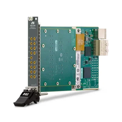
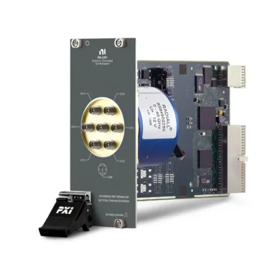
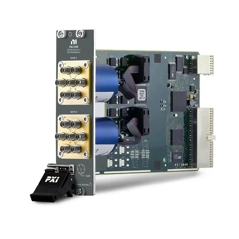
PXI-2796 RF Multiplexer Switch Module
The PXI-2796 is a 40 GHz, 50 Ω PXI RF multiplexer switch module featuring two independent 6×1 SP6T multiplexer banks. Its unterminated architecture provides high-density microwave signal routing for automated RF and microwave test systems.
With low insertion loss, high channel isolation and 14 front-panel 2.9 mm connectors, the PXI-2796 is suitable for routing multiple RF sources, measurement instruments or device-under-test connections at frequencies up to 40 GHz.
Key Features of the PXI-2796
- 40 GHz maximum switch bandwidth
- 50 Ω nominal characteristic impedance
- Two independent 6×1 SP6T multiplexer banks
- 12 RF channels and two common connections
- Unterminated multiplexer architecture
- Less than 1.1 dB insertion loss at 40 GHz
- Greater than 45 dB open-channel isolation at 40 GHz
- Maximum VSWR below 2.2 at 40 GHz
- Up to 18 W RF power at frequencies through 18 GHz
- Maximum cold-switching voltage of 30 Vrms
- Maximum current of 0.6 Arms per channel
- Electromechanical, nonlatching relays
- PXI hardware triggering support
- Fourteen 2.9 mm female RF connectors
PXI-2796 Technical Specifications
| Product Model | PXI-2796 |
|---|---|
| Part Number | 782356-01 |
| Product Type | RF and Microwave Multiplexer Switch Module |
| Bus Type | PXI Hybrid |
| Switch Topology | Dual 6×1 multiplexer, SP6T |
| Number of Banks | 2 |
| RF Channels | 12 channels plus two common ports |
| Termination | Unterminated |
| Maximum Frequency | 40 GHz |
| Characteristic Impedance | 50 Ω nominal |
| Maximum Insertion Loss | Less than 1.1 dB at 40 GHz |
| Open-Channel Isolation | Greater than 45 dB at 40 GHz |
| Maximum VSWR | Less than 2.2 at 40 GHz |
| Maximum Cold-Switching Voltage | 30 Vrms |
| Maximum Current | 0.6 Arms per channel |
| Maximum RF Power | 18 W into a 50 Ω load, frequency dependent |
| Relay Set/Reset Time | 15 ms |
| Recommended Cycling Rate | 5 channels/s |
| Mechanical Relay Life | 2 × 10⁶ cycles |
| Relay Type | Electromechanical, nonlatching |
| I/O Connectors | 14 × 2.9 mm female connectors |
| PXI Slots Required | 2 |
| Operating Temperature | 0°C to 55°C |
| Dimensions | 21.6 × 4.1 × 13.0 cm |
| Weight | Approximately 378 g |
PXI-2796 Part Number and Configuration
| Model | Part Number | Configuration |
|---|---|---|
| PXI-2796 | 782356-01 | 40 GHz, 50 Ω, dual 6×1 unterminated RF multiplexer |
Dual 6×1 SP6T Multiplexer Architecture
The PXI-2796 contains two independent multiplexer banks. Each bank routes one of six RF channels to a common port, allowing the module to connect as many as 12 RF paths to two separate instruments or test points.
The two banks can be controlled independently. This makes it possible to route signals between separate RF sources and receivers or to test two RF paths within the same automated system.
Unterminated RF Signal Paths
The PXI-2796 uses an unterminated architecture. Channels that are not connected to a common port are left open rather than internally terminated into 50 Ω loads.
This architecture provides two 6×1 banks in a compact module, but engineers must consider reflections from open channels. If internal termination is required to protect a source or maintain port matching, the single-bank terminated PXI-2797 may be more appropriate.
Insertion Loss Across Frequency
| Frequency | Maximum Insertion Loss |
|---|---|
| Up to 3 GHz | Less than 0.2 dB |
| Up to 8 GHz | Less than 0.3 dB |
| Up to 12.4 GHz | Less than 0.4 dB |
| Up to 18 GHz | Less than 0.5 dB |
| Up to 26.5 GHz | Less than 0.7 dB |
| Up to 40 GHz | Less than 1.1 dB |
Actual system insertion loss also includes the effects of cables, adapters, connectors and fixture transitions. These additional losses should be included when calculating the complete RF path budget.
RF Power Handling
| Frequency Range | Maximum RF Power into 50 Ω |
|---|---|
| Up to 18 GHz | 18 W |
| Above 18 GHz to 26.5 GHz | 15 W |
| Above 26.5 GHz to 40 GHz | 5 W |
RF power capacity decreases as frequency increases. The 18 W rating must not be applied across the entire 40 GHz operating range. Switching power is also limited by the module’s maximum voltage and current ratings.
Cold-Switching Requirement
The PXI-2796 is specified for cold switching. RF power should be removed before changing the relay state and restored only after the new connection has settled.
During relay movement, the selected path can become temporarily unterminated. Switching an active RF source may create reflections that could damage sensitive source or receiver equipment.
PXI Triggering and Automated Routing
The PXI-2796 accepts input triggers from PXI trigger lines 0 through 7. Triggered switching allows its relay operations to be coordinated with signal generators, analyzers, digitizers and other instruments.
The recommended relay cycling rate is five channels per second. Applications should include sufficient settling time before beginning the next RF measurement.
Typical PXI-2796 Applications
- RF and microwave automated testing
- Multiple-source signal routing
- Multiple-device RF characterization
- Routing signals to RF downconverters
- Routing high-order harmonics from RF upconverters
- Radar and electronic warfare testing
- Satellite communications testing
- 5G and wireless component validation
- Amplifier, filter and mixer testing
- Antenna and transceiver measurements
- Semiconductor RF device testing
NI-SWITCH Software Support
The PXI-2796 is controlled through the NI-SWITCH instrument driver. NI-SWITCH provides functions for relay control, channel routing, trigger configuration, route validation and relay-count monitoring.
NI Switch Executive can be used to create named signal routes and manage larger switching systems. Application development is supported in LabVIEW, LabWindows/CVI, C and compatible Microsoft programming environments.
RF Cable and Connector Selection
The module provides fourteen front-panel 2.9 mm female connectors. Use phase-stable 50 Ω microwave cables, connectors and adapters rated for the highest frequency and RF power in the application.
Connector interfaces should be clean and inspected before use. Apply the specified connector torque of 0.8 N·m to 1.1 N·m using an appropriate calibrated torque wrench. Excessive or insufficient torque can degrade repeatability or damage the RF interface.
PXI Chassis Integration
The PXI-2796 is a two-slot 3U PXI/cPCI module with a PXI Hybrid bus interface. Confirm that two adjacent compatible slots are available before installation.
The module can be combined with RF signal generators, vector signal analyzers and other PXI instruments to create an integrated microwave test system. Maintain proper chassis airflow and install filler panels in unused slots.
PXI-2796 Troubleshooting
The module is not detected by the system
Verify that the PXI-2796 is fully seated in a compatible PXI Hybrid slot and that the adjacent slot provides sufficient physical clearance. Confirm that the chassis, controller and NI-SWITCH driver are operating correctly.
The measured insertion loss is too high
Inspect and clean the RF connectors, verify cable frequency ratings and tighten each connector to the recommended torque. Measure the cables and adapters separately to determine whether the additional loss originates outside the module.
The signal contains unexpected reflections
The PXI-2796 is unterminated, so unselected channels remain open. Verify source and load matching, remove unnecessary adapters and consider the terminated PXI-2797 when open-channel reflections are unacceptable.
The relay does not switch reliably
Remove RF power before changing channels, verify trigger timing and allow at least the specified relay operating and settling time. Review the relay count if a frequently used channel begins to behave inconsistently.
High-frequency measurements are not repeatable
Use phase-stable cables, avoid moving cables after calibration and maintain consistent connector torque. Recalibrate the complete measurement path whenever cables, adapters or switch routes are changed.
The RF source reports a mismatch or protection fault
Because the signal path may be temporarily unterminated during switching, disable the RF output before operating the relay. Re-enable the signal only after the new route has been established.
PXI-2796 Compared with Related RF Switch Modules
| Model | Topology | Bandwidth | Termination | Best Suited For |
|---|---|---|---|---|
| PXI-2796 | Dual 6×1 SP6T | 40 GHz | Unterminated | High-density RF multiplexing |
| PXI-2797 | Single 6×1 SP6T | 40 GHz | Internally terminated | Applications requiring termination of open channels |
| PXI-2798 | Dual transfer switch | 40 GHz | Application dependent | Inserting or bypassing RF components |
| PXI-2799 | Dual SPDT | 40 GHz | Application dependent | General-purpose RF path selection |
Recommended Related Products
- PXI-2797 Terminated RF Multiplexer – A 40 GHz single 6×1 multiplexer with internal termination for unselected channels.
- PXI-2798 RF Transfer Switch – A dual transfer switch for inserting or bypassing devices in microwave signal paths.
- PXI-2799 RF Relay Module – A dual SPDT module for general-purpose RF signal selection up to 40 GHz.
- PXIe-5841 Vector Signal Transceiver – An RF instrument for generation and analysis in automated wireless test systems.
- PXIe-1092 PXI Express Chassis – A modular chassis for building synchronized RF and mixed-signal test systems.
Additional RF switching and measurement products are available in the NI PXI Modules category.
Selecting the PXI-2796
Choose the PXI-2796 when an application requires two independent 6×1 RF multiplexers, operation through 40 GHz and high channel density in a PXI system. It is appropriate when open, unterminated channels are acceptable.
Select the PXI-2797 when internal termination is required. Choose the PXI-2798 for transfer-switch routing or the PXI-2799 for simpler dual-SPDT signal selection.
Why Choose the PXI-2796?
- Provides two independent 6×1 banks in one module
- Routes RF and microwave signals up to 40 GHz
- Maintains low insertion loss across a broad frequency range
- Offers high isolation between open channels
- Supports PXI hardware-triggered operation
- Integrates with NI-SWITCH and NI Switch Executive
- Reduces the space required for high-density RF routing
Frequently Asked Questions
What is the PXI-2796 used for?
The PXI-2796 routes RF and microwave signals between multiple sources, instruments and devices under test. It is commonly used in automated RF component, wireless and semiconductor testing.
What is the switching topology?
The module contains two independent 6×1 SP6T multiplexer banks, providing 12 channel ports and two common ports.
What is the maximum operating frequency?
The PXI-2796 supports RF and microwave signal routing at frequencies up to 40 GHz.
Is the PXI-2796 internally terminated?
No. It uses an unterminated architecture, meaning that unselected channels remain open.
Can the PXI-2796 switch a live RF signal?
NI specifies cold switching for this module. RF power should be removed before changing the relay state and restored only after the route has settled.
What RF connectors does the module use?
The PXI-2796 provides fourteen front-panel 2.9 mm female connectors.
How many PXI slots does it require?
The PXI-2796 occupies two adjacent 3U PXI slots.
What is the part number for the PXI-2796?
The standard NI part number for the PXI-2796 is 782356-01.
Request a Quote for the PXI-2796
Contact us for current availability, lead time and project pricing for the PXI-2796 40 GHz RF Multiplexer Switch Module. We can also help identify compatible RF cables, PXI chassis, signal generators, analyzers and related microwave switch modules for your test system.















