






PXI-2798 Dual-Transfer 40 GHz PXI RF Switch Module
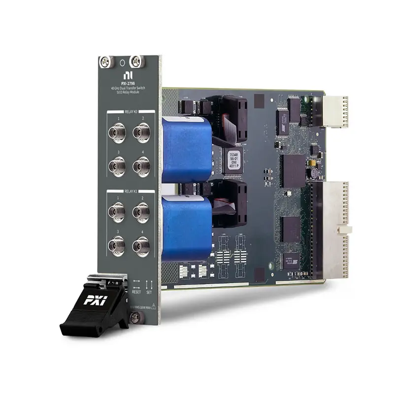
The PXI-2798 is a dual-transfer PXI RF switch module designed for routing microwave signals at frequencies up to 40 GHz. Its two independently controlled transfer relays can insert or remove devices, filters, attenuators and other components from high-frequency signal paths.
The module combines electromechanical latching relays, eight front-panel 2.92 mm RF connectors and less than 1 dB insertion loss at frequencies up to 40 GHz. It is suitable for automated RF validation, microwave component testing, signal-path configuration and high-order harmonic measurements.
Key Features of the PXI-2798
- Dual-transfer RF switch topology
- Two independently controlled transfer relays
- DC to 40 GHz switching bandwidth
- Less than 1 dB insertion loss at up to 40 GHz
- 50 Ω characteristic impedance
- Electromechanical latching relay technology
- Eight female 2.92 mm RF connectors
- 30 VAC maximum switching voltage
- 0.6 A maximum AC carry current
- 5 cycles/s maximum scan rate
- PXI hybrid-bus interface
- 3U, two-slot PXI module
- NI-SWITCH software support
- NI Switch Executive compatibility
PXI-2798 Technical Specifications
| Product Model | PXI-2798 |
|---|---|
| Part Number | 782358-01 |
| Product Type | PXI microwave transfer switch module |
| Topology | Dual transfer |
| Number of Transfer Relays | 2 |
| Frequency Range | DC to 40 GHz |
| Characteristic Impedance | 50 Ω |
| Insertion Loss | Less than 1 dB at up to 40 GHz |
| Relay Type | Electromechanical, latching |
| Relay Manufacturer Series | Radiall R578 series |
| Contact Material | Gold-plated beryllium copper |
| Maximum Switching Voltage | 30 VAC |
| Maximum AC Carry Current | 0.6 A |
| Maximum Scan Rate | 5 cycles/s |
| Front-Panel Connectors | 8 × female 2.92 mm RF connectors |
| Recommended Connector Torque | 0.8 to 1.1 N·m, or 7 to 10 in-lb |
| Bus Interface | PXI hybrid |
| Module Size | 3U, two-slot PXI/cPCI module |
| Dimensions | 21.6 × 4.1 × 13.0 cm |
| Weight | 279 g |
| Operating Temperature | 0°C to 55°C |
| Storage Temperature | −20°C to 70°C |
| Operating Humidity | 5% to 85%, noncondensing |
| Maximum Operating Altitude | 2,000 m |
| Software Support | NI-SWITCH and NI Switch Executive |
PXI-2798 Part Number and RF Accessories
| Item | Part Number or Interface | Description |
|---|---|---|
| PXI-2798 | 782358-01 | Dual-transfer, 40 GHz PXI microwave switch module |
| RF Test Cables | 2.92 mm, 50 Ω | Phase-stable microwave cables rated for the required frequency |
| Connector Torque Wrench | 5/16-inch RF torque wrench | Used to tighten RF connections to the recommended torque |
| Connector Savers | 2.92 mm compatible | Help reduce wear on frequently used front-panel connectors |
| RF Adapters | Application dependent | Adapters must support 50 Ω operation and the required frequency range |
The PXI-2798 does not require a dedicated terminal block. Signals connect directly to its eight front-panel RF connectors. For operation approaching 40 GHz, use precision 2.92 mm cables, adapters and calibration standards with suitable microwave ratings.
Dual-Transfer Switch Architecture
The PXI-2798 contains two independently controlled transfer switches. A transfer switch provides four RF ports and changes two signal paths simultaneously, allowing a component to be inserted into or bypassed from a test path.
This topology is particularly useful when a device must be compared against a through connection. Test software can switch between the device path and bypass path without manually moving microwave cables.
PXI-2798 Relay States
Each transfer relay has a reset state and a set state. In the reset state, the standard PXI-2798 topology inserts the connected device or component into the signal path. Changing the relay to the set state routes the signal through the bypass path and removes the component from the active connection.
The exact system behavior depends on how the four ports of each relay are wired. Engineers should document the set and reset paths in the test fixture so that every software command produces the intended RF route.
DC to 40 GHz Frequency Coverage
The PXI-2798 supports signal routing from DC through 40 GHz. This wide operating range allows the same module to handle low-frequency signals, microwave test signals and high-order harmonics generated by RF devices.
Performance at the upper end of the frequency range depends heavily on the complete test path. Cables, adapters, connector condition, fixture transitions and calibration methods must all support 40 GHz operation.
Low Insertion Loss
The PXI-2798 provides less than 1 dB insertion loss at frequencies up to 40 GHz. Low insertion loss helps preserve signal amplitude and available measurement dynamic range when the switch is installed between an RF source, device under test and measurement instrument.
The total system loss includes the switch module, cables, adapters, connector interfaces and test fixture. Characterize or calibrate the complete path when accurate power measurements are required.
50 Ω RF Signal Paths
The module uses a 50 Ω RF architecture compatible with common microwave signal generators, spectrum analyzers, vector network analyzers, RF digitizers and other test instruments.
All connected cables, adapters, attenuators and terminations should also use a 50 Ω impedance. Impedance discontinuities can increase reflections and degrade amplitude and phase accuracy, especially at higher microwave frequencies.
Electromechanical Latching Relays
The PXI-2798 uses Radiall R578-series electromechanical latching relays. Latching construction allows a relay to remain in its selected position without continuously energizing its actuator.
Electromechanical relays provide physical metal-contact signal paths and can route signals from DC through microwave frequencies. Because the relay contacts are mechanical, service life depends on switching power, operating frequency and the number of switching operations.
Eight 2.92 mm RF Connectors
The front panel provides eight female 2.92 mm RF connectors, four for each transfer relay. The 2.92 mm interface is designed for precision microwave connections and supports the module’s 40 GHz frequency range when used with correctly rated components.
Some SMA connectors can mechanically mate with 2.92 mm interfaces, but standard SMA cables and adapters may not deliver specified performance at 40 GHz. Use precision 2.92 mm components for measurements requiring the full module bandwidth.
RF Connector Care
Inspect every connector before use. Damaged center conductors, contaminated interfaces or worn threads can increase insertion loss, reduce repeatability and permanently damage the module’s front-panel connectors.
Align connectors before engaging the threads, rotate the coupling nut rather than the cable body and use the recommended torque of 0.8 to 1.1 N·m. Do not apply lateral force to connected microwave cables.
Device Insertion and Bypass Testing
A primary PXI-2798 application is inserting and removing an RF component from a measurement path. The component can be a filter, amplifier, attenuator, coupler, cable assembly or other two-port microwave device.
Switching between the component and bypass paths allows test software to compare results, perform reference measurements or verify the effect of the component without stopping the automated sequence.
High-Order Harmonic Routing
The 40 GHz bandwidth makes the PXI-2798 suitable for routing high-order harmonics produced by RF upconverters, amplifiers and transmitters. These harmonics can be directed to a suitable spectrum analyzer or other microwave measurement instrument.
Every part of the test path must support the highest harmonic being measured. A cable or adapter with insufficient bandwidth can introduce loss or reflections that make the harmonic measurement inaccurate.
RF Source and Receiver Routing
The transfer topology can route different RF sources or signal paths to microwave receivers and downconverters. This supports systems that must compare sources, alternate between test configurations or provide a bypass route for calibration.
Before changing routes, verify that the connected sources are compatible. Avoid configurations that directly connect two active RF outputs or expose a sensitive receiver to excessive power.
Cold Switching and Hot Switching
Relay life and signal integrity are generally improved when RF power is removed before changing the relay state. This operating method is commonly called cold switching.
If the application requires hot switching, verify the permissible switching power at the operating frequency in the official PXI-2798 specifications. RF power capability can decrease as frequency increases, and transient energy can accelerate contact wear.
Microwave Path Calibration
For precision testing, calibrate the measurement system with the PXI-2798 and associated cables included in the signal path. Depending on the application, calibration may involve power-sensor corrections, path-loss tables or vector network analyzer error correction.
Separate correction data may be needed for each relay and each switch state. Recording state-specific loss and phase information helps maintain measurement accuracy after automated route changes.
PXI System Integration
The PXI-2798 uses a PXI hybrid interface and occupies two chassis slots. It can be combined with PXI RF signal generators, analyzers, digitizers, frequency references and other switching modules to build a compact automated microwave test platform.
Before installation, confirm that two adjacent compatible slots are available. Verify chassis cooling, controller compatibility, module clearance and the required NI-SWITCH software version.
NI-SWITCH Software Support
The PXI-2798 is controlled with the NI-SWITCH instrument driver. NI-SWITCH provides functions for initializing the module, connecting and disconnecting routes, changing relay states and integrating switching operations into automated test software.
The driver supports LabVIEW, LabWindows/CVI and compatible text-based programming environments. The published topology name is 2798/Dual Transfer.
NI Switch Executive Integration
NI Switch Executive allows developers to assign meaningful names to physical switch routes. Named routes can make complex RF test programs easier to understand and maintain, particularly when multiple switch modules are installed in one system.
Route definitions can represent paths such as DUT insertion, DUT bypass, calibration reference or analyzer selection. This reduces the need to manage individual relay connections directly throughout the application code.
Typical PXI-2798 Applications
- Automated microwave component testing
- DC to 40 GHz RF signal routing
- Device insertion and bypass testing
- Filter and attenuator validation
- Amplifier test-system routing
- High-order harmonic measurements
- RF upconverter and downconverter testing
- Signal-source selection
- Calibration-path switching
- Vector network analyzer test systems
- Spectrum-analyzer signal routing
- Production microwave testing
Automated RF Component Testing
In an automated component test system, one PXI-2798 relay can insert a device into the signal path while its alternate route provides a direct through connection. Software can compare the two measurements and calculate the additional loss or response introduced by the device.
The second independent transfer relay can control another device, create an additional reference path or route the signal at a different point in the test system.
Production Microwave Test Systems
The module can reduce manual cable changes in production RF test stations. Automated routing improves repeatability and allows the same instruments to test multiple signal configurations under software control.
Production maintenance should include regular connector inspection, verification with a known reference path and monitoring of relay operation counts where supported by the software environment.
PXI-2798 Troubleshooting
The PXI-2798 is not detected in NI MAX
Confirm that the module is fully installed in two compatible adjacent chassis slots. Check chassis power, controller communication and NI-SWITCH installation, then restart NI Measurement & Automation Explorer and rescan the system.
The RF signal is missing after switching
Verify the software topology and confirm whether the relay is in its set or reset state. Check all four connections associated with the selected transfer relay and confirm that the source and receiver are connected to the intended ports.
Insertion loss is higher than expected
Inspect and clean the RF connectors according to approved microwave-connector procedures. Check cable frequency ratings, adapter quality, connector torque and the condition of the test fixture. Measure each component separately to locate the excessive loss.
Measurements change when cables are moved
Use phase-stable microwave cables and provide strain relief. Cable flexure can change loss and phase, particularly near 40 GHz. Recalibrate the system after changing the cable arrangement.
Performance degrades at high frequency
Confirm that every cable, adapter, termination and instrument port supports the required frequency. Standard SMA components may fit mechanically but may not provide adequate performance at 40 GHz.
The relay does not change state
Confirm that the correct relay bank and route are being addressed. Reset the module through NI-SWITCH and verify operation without applied RF power. If the state still does not change, inspect the module in NI MAX and run the available diagnostics.
Results differ between the two transfer relays
Characterize each relay path independently. Small differences in switch paths, cables and adapters can produce different loss and phase responses. Store separate correction data when the application requires precision measurements.
RF connectors show visible wear
Stop using damaged connectors to avoid harming mating components. Connector savers can reduce wear in fixtures that are disconnected frequently. Maintain the specified connector torque and avoid overtightening.
PXI-2798 Comparison
| Switch Type | Routing Capability | Best Suited For |
|---|---|---|
| PXI-2798 | Dual-transfer switching through 40 GHz | Inserting or bypassing two-port microwave components |
| High-frequency SPDT switch | Selects one of two RF paths | Source, receiver or antenna selection |
| RF multiplexer | Connects one common port to multiple channels | Testing multiple devices or test points with one instrument |
| RF matrix switch | Provides multiple interconnected inputs and outputs | Complex multi-instrument RF routing systems |
PXI-2798 vs SPDT RF Switches
An SPDT switch selects between two signal paths using one common port. A transfer switch changes two connections at the same time, making it better suited to inserting a two-port device while maintaining an alternate bypass path.
Choose the PXI-2798 when the system must switch both the input and output sides of a component simultaneously. Choose an SPDT module when the application only needs to select one of two sources, loads or destinations.
Recommended Related Products
- PXI-2799 RF Switch Module
- PXI-2598 RF Switch Module
- PXI-2599 RF Switch Module
- PXI-2596 RF Multiplexer Switch Module
- View More NI PXI and PXI Express Modules
Selecting the Right RF Switch Module
Choose the PXI-2798 when the application requires two independent transfer switches, operation through 40 GHz and the ability to insert or bypass microwave components automatically.
For selecting between individual RF sources or destinations, an SPDT switch may provide a simpler topology. For connecting one instrument to many test points, consider an RF multiplexer. Systems requiring many simultaneous input-to-output combinations may require a matrix architecture.
Why Choose the PXI-2798?
- Provides two independent transfer switches in one module
- Routes signals from DC through 40 GHz
- Offers less than 1 dB insertion loss at up to 40 GHz
- Supports automated device insertion and bypass testing
- Uses precision 2.92 mm RF interfaces
- Employs electromechanical latching relays
- Integrates with modular PXI RF test systems
- Supports NI-SWITCH and NI Switch Executive
Frequently Asked Questions
What is the PXI-2798?
The PXI-2798 is a dual-transfer PXI microwave switch module that routes RF signals from DC through 40 GHz.
What is the PXI-2798 part number?
The standard NI part number for the PXI-2798 is 782358-01.
How many transfer switches does the module provide?
The PXI-2798 provides two independently controlled transfer switches. Each switch has four RF ports.
What is the maximum frequency?
The module supports RF and microwave signal routing at frequencies up to 40 GHz.
What is the insertion loss?
NI specifies less than 1 dB insertion loss at frequencies up to 40 GHz. Total test-system loss also includes cables, adapters and fixture connections.
What connectors does the PXI-2798 use?
The front panel provides eight female 2.92 mm RF connectors. Precision 2.92 mm cables are recommended when using the module near its maximum frequency.
Can the PXI-2798 bypass a device under test?
Yes. Its transfer topology is designed to insert a two-port device into the RF path or remove it by selecting the alternate bypass route.
Does the PXI-2798 use solid-state switches?
No. It uses electromechanical latching relays with gold-plated beryllium-copper contacts.
What connector torque should be used?
NI specifies a connector torque of 0.8 to 1.1 N·m, equivalent to approximately 7 to 10 in-lb.
Which software controls the PXI-2798?
The module is controlled with NI-SWITCH and can be integrated with NI Switch Executive. Its published NI-SWITCH topology is 2798/Dual Transfer.
How many PXI slots does the PXI-2798 occupy?
The PXI-2798 is a 3U module that occupies two adjacent PXI chassis slots.
Request a Quote for the PXI-2798
Contact us for current availability, lead time and project pricing for the PXI-2798 Dual-Transfer 40 GHz PXI RF Switch Module. We can also help identify compatible 2.92 mm microwave cables, adapters, PXI chassis and related RF switching modules for your automated test system.















