






Product Introduction
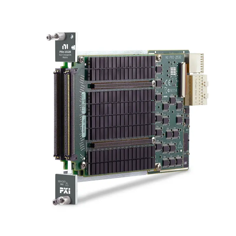
The NI PXIe-2532B is a high-density PXI Express matrix switch module designed for automated test, data acquisition, electronic validation, semiconductor test, and signal-routing applications.
The PXIe-2532B provides a flexible switching architecture that can be configured with different terminal blocks to create matrix topologies with up to 512 crosspoints. This allows engineers to route multiple instruments to multiple devices under test or test points through a compact PXI switching platform.
With its high channel density, flexible matrix configurations, software-controlled switching, and PXI Express integration, the PXIe-2532B is well suited for automated test systems where large numbers of signals must be dynamically connected between measurement instruments and DUT interfaces.
Product Overview
The National Instruments PXIe-2532B is a PXI matrix switch designed to simplify complex signal-routing architectures.
Instead of manually reconnecting cables between instruments and DUT test points, engineers can use the PXIe-2532B to control signal paths programmatically.
A simplified automated test architecture is:
PXI Instruments → PXIe-2532B Matrix Switch → DUT Test Points
The test software selects the required matrix crosspoints, performs the measurement, changes the routing configuration, and continues to the next test automatically.
Key Features
High-Density Matrix Switching
The PXIe-2532B is designed for applications requiring a large number of switching connections in limited PXI chassis space.
Depending on the selected terminal block and topology, the module can provide up to 512 matrix crosspoints.
High-density switching is particularly valuable in:
- Automated functional test
- Electronic production test
- Semiconductor test
- PCB validation
- Data acquisition systems
- Design verification
- High-channel-count measurement systems
Flexible Matrix Topologies
The PXIe-2532B can be configured into different matrix arrangements through compatible terminal blocks and accessories.
A matrix switch consists of rows and columns connected through programmable crosspoints.
For example:
Rows → Measurement Instruments
Columns → DUT Test Points
Closing a crosspoint connects the selected row to the selected column.
This architecture provides substantially greater routing flexibility than a simple multiplexer when several instruments and DUT connections must interact.
Up to 512 Crosspoints
The PXIe-2532B supports configurations providing up to 512 crosspoints.
Crosspoint count represents the number of programmable intersections available between matrix rows and columns.
For example, a matrix architecture can allow multiple measurement instruments to be selectively connected to a large number of DUT test points without manually changing physical connections.
Software-Controlled Signal Routing
The PXIe-2532B provides software-controlled switching, allowing signal routes to be automatically changed according to the test sequence.
A typical automated process may include:
- Configure the matrix topology.
- Select the required instrument.
- Close the appropriate crosspoint.
- Perform the measurement.
- Open the previous connection.
- Select another DUT test point.
- Repeat the measurement.
- Continue until all required test points are complete.
300 V Switching Capability
Depending on the selected configuration and terminal block, the PXIe-2532B supports signal routing for applications requiring voltages up to approximately 300 V.
Actual allowable voltage depends on the terminal block, topology, signal configuration, insulation requirements, and applicable safety limits.
Engineers should verify the complete signal path before routing higher-voltage signals.
Up to 2 A Switching Current
The PXIe-2532B supports switching currents up to approximately 2 A under applicable operating conditions.
Current capability depends on factors including the selected terminal block, switching configuration, simultaneous channel usage, signal voltage, and power limits.
Electromechanical Relay Architecture
The PXIe-2532B uses electromechanical relay technology to provide physical signal-path switching.
Electromechanical relays are commonly used in automated test systems because they can provide:
- Low contact resistance
- Good signal isolation
- DC signal compatibility
- AC signal compatibility
- Bidirectional signal routing
- Broad measurement-instrument compatibility
PXI Express Platform
The PXIe-2532B is designed for the PXI Express platform and can operate alongside other PXI measurement and stimulus instruments.
This enables signal switching to be integrated directly with:
- Digital multimeters
- Source Measure Units
- Data acquisition modules
- Programmable power supplies
- Oscilloscopes and digitizers
- Waveform generators
- LCR meters
- Other PXI switching modules
Technical Specifications
| Parameter | Description |
|---|---|
| Product Type | PXI Matrix Switch Module |
| Model | NI PXIe-2532B |
| Platform | PXI Express |
| Switch Architecture | Matrix |
| Maximum Crosspoints | Up to 512 |
| Maximum Switching Voltage | Up to Approximately 300 V, Configuration Dependent |
| Maximum Switching Current | Up to Approximately 2 A, Configuration Dependent |
| Relay Type | Electromechanical |
| Signal Direction | Bidirectional |
| Software-Controlled Switching | Supported |
| Matrix Configuration | Terminal Block Dependent |
| Primary Applications | Automated Test, Signal Routing, Data Acquisition, Electronic Validation and Production Test |
What Is a Matrix Switch?
A matrix switch is a signal-routing device that provides programmable connections between a set of rows and columns.
The basic architecture can be represented as:
Rows × Columns = Matrix Crosspoints
Each crosspoint represents a potential electrical connection between one row and one column.
By opening and closing these crosspoints, automated test software can dynamically create different signal-routing configurations.
How Does the PXIe-2532B Work?
The PXIe-2532B contains a high-density relay switching architecture controlled through the PXI system.
Compatible terminal blocks determine the available matrix topology and external signal connections.
During operation, software commands control individual relay crosspoints to create the required signal path.
A typical sequence is:
Test Software → PXIe-2532B → Select Crosspoint → Connect Instrument to DUT → Measure → Disconnect → Select Next Crosspoint
Matrix Switch vs Multiplexer
A matrix switch and a multiplexer both route signals, but their routing architectures are different.
| Feature | Matrix Switch | Multiplexer |
|---|---|---|
| Architecture | Rows × Columns | Multiple Inputs to Common Output |
| Routing Flexibility | High | Moderate |
| Multiple Instruments | Well Suited | More Limited |
| Crosspoint Connections | Yes | No Traditional Matrix |
| Typical Application | Complex Automated Test Routing | Scanning Multiple Measurement Channels |
PXIe-2532B for Automated Test
Automated test systems frequently require several instruments to access many DUT test points.
Without an automated switch, these connections would require dedicated wiring or manual cable changes.
The PXIe-2532B allows test software to dynamically configure these signal paths.
A typical system may use:
PXI DMM → PXIe-2532B → DUT Test Point 1
PXI DMM → PXIe-2532B → DUT Test Point 2
PXI SMU → PXIe-2532B → DUT Test Point 3
PXI Power Supply → PXIe-2532B → Compatible DUT Connection
Electronic Functional Test
The PXIe-2532B is suitable for automated electronic functional test systems where many circuit nodes must be accessed by different instruments.
Typical measurements may include:
- DC voltage
- Current
- Resistance
- Continuity
- Open and short tests
- Component measurements
- Power rail verification
PCB Testing
Printed circuit boards can contain hundreds of electrical test points.
A high-density matrix switch can reduce the number of dedicated measurement instruments required by allowing one instrument to access multiple test nodes sequentially.
A simplified architecture is:
Measurement Instrument → PXIe-2532B → PCB Test Fixture → Multiple Test Points
Test software automatically selects each required connection and records the measurement result.
Production Test Applications
Production environments require repeatable signal routing and minimal manual intervention.
The PXIe-2532B can automate connection changes between instruments and DUTs, helping create repeatable production test sequences.
Typical applications include:
- PCB production test
- Electronic module testing
- End-of-line test
- Manufacturing quality control
- Automated pass/fail testing
Data Acquisition Signal Routing
The PXIe-2532B can be used with compatible PXI modules to create high-channel-count measurement systems.
For example:
Multiple Sensors → PXIe-2532B → PXI Measurement Instrument
The matrix can select which sensor or test point is connected to the measurement instrument at a particular time.
PXIe-2532B with a PXI Digital Multimeter
One of the most common applications for a matrix switch is expanding the number of test points accessible by a precision digital multimeter.
A typical architecture is:
PXI DMM → PXIe-2532B → Multiple DUT Test Points
The DMM can remain fixed while the matrix switch automatically routes different DUT signals to the instrument.
This architecture can be used for:
- Voltage measurements
- Resistance measurements
- Continuity testing
- Current measurements where appropriate
- Production functional testing
PXIe-2532B with a Source Measure Unit
The PXIe-2532B can be combined with a compatible PXI Source Measure Unit to route precision DC stimulus and measurements to multiple DUT connections.
A simplified architecture is:
PXI SMU → PXIe-2532B → Multiple DUT Test Points
This can reduce the number of dedicated SMU channels required when DUT terminals do not need to be measured simultaneously.
PXIe-2532B for Semiconductor Test
Semiconductor test systems can require complex routing between precision instruments and DUT pins.
The PXIe-2532B can be incorporated into compatible semiconductor test architectures to route:
- DC bias signals
- Voltage measurements
- Current measurements
- Continuity test signals
- Open and short test signals
- Parametric measurement connections
Switch leakage, contact resistance, thermal EMF, voltage, current, and isolation requirements should be evaluated carefully for precision semiconductor measurements.
Open and Short Testing
The PXIe-2532B can be used in automated open and short test systems.
A matrix switch can sequentially connect different DUT pins to a measurement instrument to verify electrical continuity and detect unwanted connections.
This is useful for:
- Semiconductor devices
- PCB assemblies
- Cable assemblies
- Connectors
- Electronic modules
Cable and Harness Testing
High-density matrix switching can also be useful for cable and wire-harness test systems.
The matrix can automatically route measurement signals between multiple connector pins to test:
- Continuity
- Open circuits
- Short circuits
- Resistance
- Pin-to-pin connectivity
Matrix Expansion
For applications requiring more connections than a single module can provide, multiple PXIe-2532B modules can be incorporated into a larger switching architecture.
This allows engineers to scale the number of available signal paths according to the DUT and test-system requirements.
Expansion architecture should account for signal integrity, relay resistance, leakage, wiring complexity, and overall system topology.
Terminal Block Selection
The PXIe-2532B requires a compatible terminal block or connectivity accessory to implement the required matrix configuration.
The selected terminal block can determine important characteristics such as:
- Matrix topology
- Number of rows
- Number of columns
- Number of crosspoints
- External connector type
- Signal voltage capability
- Current capability
- System wiring architecture
For this reason, the PXIe-2532B module and terminal block should be selected as a complete switching solution rather than considering the module alone.
Signal Routing Considerations
Before routing a signal through the PXIe-2532B, engineers should verify that the complete signal path meets the electrical requirements of the application.
Important parameters include:
- Signal voltage
- Signal current
- Switching power
- Contact resistance
- Relay lifetime
- Isolation
- Leakage current
- Thermal EMF
- Signal bandwidth
- Terminal block limitations
Relay Contact Resistance
Contact resistance is an important consideration when routing precision or higher-current signals.
Every relay contact introduces some resistance into the measurement path.
For precision resistance measurements or high-current applications, engineers should account for the complete resistance of:
- Relay contacts
- Terminal block
- Cables
- Connectors
- DUT fixture
Relay Lifetime
The PXIe-2532B uses electromechanical relays, which have a finite mechanical and electrical operating life.
Relay lifetime depends strongly on the electrical load being switched.
Switching low-level signals generally places less electrical stress on relay contacts than repeatedly switching high voltage or high current.
Test-system software should therefore minimize unnecessary relay operations when practical.
PXIe-2532B vs Multiplexer Switch
| Feature | PXIe-2532B Matrix | PXI Multiplexer |
|---|---|---|
| Routing Architecture | Rows × Columns | Many-to-One |
| Routing Flexibility | Very High | High for Scanning |
| Multiple Instruments | Excellent | More Limited |
| Crosspoints | Up to 512 | Not Matrix-Based |
| Best Application | Complex Instrument-to-DUT Routing | Multi-Channel Scanning |
PXIe-2532B vs General-Purpose Relay Module
| Feature | PXIe-2532B | General-Purpose Relay Module |
|---|---|---|
| Architecture | Matrix | Independent Relays |
| Channel Density | Very High | Model Dependent |
| Complex Routing | Excellent | More Limited |
| Automated Scanning | Supported | Supported |
| Primary Application | High-Density Signal Routing | General Signal Switching |
PXIe-2532B in a Complete PXI System
The PXIe-2532B can serve as the central signal-routing component within a complete PXI system.
A typical automated test platform may include:
- PXI Chassis
- PXI Controller
- PXIe-2532B matrix switch
- PXI Modules
- PXI digital multimeters
- PXI Source Measure Units
- PXI programmable power supplies
- PXI data acquisition modules
- PXI oscilloscopes and digitizers
The switching system dynamically connects the required measurement or stimulus instrument to the appropriate DUT test point.
Software and Driver Support
The PXIe-2532B is designed for software-controlled switching in automated PXI systems.
Test software can control functions such as:
- Opening relay connections
- Closing relay connections
- Creating signal routes
- Disconnecting routes
- Scanning multiple channels
- Changing matrix configurations
- Coordinating switching with measurements
This allows signal routing to become an integrated part of the automated test sequence.
PXIe-2532B Selection Considerations
Selecting a matrix switch requires more than comparing the total number of crosspoints.
Before purchasing the PXIe-2532B, engineers should verify:
- Required matrix topology
- Number of instrument connections
- Number of DUT connections
- Required number of crosspoints
- Maximum signal voltage
- Maximum signal current
- Maximum switching power
- Required bandwidth
- Contact resistance requirements
- Leakage requirements
- Isolation requirements
- Relay lifetime requirements
- Required terminal block
- Cable and fixture requirements
- PXI Express chassis compatibility
Industries
- Automated Test Equipment
- Electronic Manufacturing
- Semiconductor Test
- Automotive Electronics
- Aerospace and Defense
- Communication Equipment
- Industrial Electronics
- Research and Development
- Data Acquisition
Applications
Automated Signal Routing
The PXIe-2532B automatically routes measurement and stimulus signals between PXI instruments and DUT test points.
PCB Functional Test
High-density matrix switching allows measurement instruments to access multiple circuit-board test points without manual reconnection.
Semiconductor Test
The matrix can route compatible DC stimulus and measurement signals between semiconductor DUT terminals and precision PXI instruments.
Digital Multimeter Channel Expansion
A PXI DMM can access many DUT measurement points through the PXIe-2532B matrix architecture.
Open and Short Testing
Programmable signal routing supports automated continuity, open-circuit, and short-circuit verification.
Cable and Harness Test
High-density crosspoint switching can automate pin-to-pin connectivity testing for cables, connectors, and wire harnesses.
Automated Production Test
Software-controlled switching provides repeatable signal routing for electronic manufacturing and production test systems.
Recommended Related Products
| NI PXIe-2532B | High-density PXI Express matrix switch with flexible terminal-block-dependent configurations and up to 512 crosspoints. |
| NI PXI-2533 | PXI multiplexer switch module for automated channel scanning and signal-routing applications. |
| NI PXIe-2525 | PXI Express switch module for automated test applications requiring a different relay topology and switching configuration. |
| NI PXIe-2725 | PXI programmable resistor module for automated resistance simulation and sensor-emulation applications. |
| NI PXIe-2727 | PXI programmable resistor module for applications requiring software-controlled resistance values. |
| NI PXI Modules | PXI and PXI Express modules for switching, data acquisition, source measurement, waveform analysis, RF testing, and automated measurement. |
Why Choose NI PXIe-2532B?
- High-density PXI matrix switching
- Up to 512 matrix crosspoints
- Flexible terminal-block-dependent topologies
- Up to approximately 300 V switching capability
- Up to approximately 2 A switching current
- Electromechanical relay architecture
- Software-controlled signal routing
- Bidirectional signal paths
- Suitable for automated test
- Suitable for PCB functional testing
- Suitable for semiconductor test systems
- Suitable for DMM channel expansion
- Suitable for open and short testing
- PXI Express modular architecture
Frequently Asked Questions
What is the NI PXIe-2532B?
The NI PXIe-2532B is a high-density PXI Express matrix switch module designed for automated signal routing between measurement instruments and devices under test.
Is the PXIe-2532B a matrix switch?
Yes. The PXIe-2532B uses a configurable matrix switching architecture in which programmable crosspoints connect matrix rows and columns.
How many crosspoints does the PXIe-2532B support?
Depending on the selected matrix topology and terminal block, the PXIe-2532B supports configurations with up to 512 crosspoints.
What is a crosspoint?
A crosspoint is a programmable switching connection located at the intersection of a matrix row and column. Closing the corresponding relay electrically connects that row and column.
What is the difference between a matrix switch and a multiplexer?
A multiplexer generally connects one of many channels to a common connection, while a matrix provides programmable connections between multiple rows and multiple columns. Matrix switching therefore provides greater routing flexibility for complex automated test systems.
Does the PXIe-2532B require a terminal block?
Yes. A compatible terminal block or connectivity accessory is required to implement the desired matrix topology and provide external signal connections.
Can different terminal blocks change the PXIe-2532B topology?
Yes. The selected terminal block is an important part of the PXIe-2532B switching architecture and determines the available matrix configuration and associated electrical characteristics.
Can the PXIe-2532B switch 300 V?
The PXIe-2532B supports configurations with voltage capability up to approximately 300 V. The exact allowable voltage depends on the selected terminal block, topology, signal configuration, insulation requirements, and applicable operating limits.
Can the PXIe-2532B switch 2 A?
The PXIe-2532B supports current levels up to approximately 2 A under applicable configurations and operating conditions. The terminal block, signal voltage, simultaneous connections, switching power, and other electrical limits must also be considered.
Can the PXIe-2532B be used with a PXI DMM?
Yes. Combining the PXIe-2532B with a PXI digital multimeter is a common architecture for automatically measuring voltage, resistance, continuity, and other electrical parameters across many DUT test points.
Can the PXIe-2532B be used with an SMU?
Yes. A compatible PXI Source Measure Unit can be routed through the PXIe-2532B to multiple DUT connections, provided the switching voltage, current, power, leakage, resistance, and accuracy requirements are satisfied.
Can the PXIe-2532B be used for semiconductor testing?
Yes. It can be incorporated into compatible semiconductor test systems for DC signal routing, continuity testing, open-short testing, and parametric measurement routing.
Can the PXIe-2532B be used for PCB testing?
Yes. High-density matrix switching is particularly useful for PCB functional test systems requiring automated access to many electrical test points.
Can the PXIe-2532B test cable harnesses?
Yes. When combined with appropriate measurement instruments and fixtures, the matrix can be used for automated continuity, open-circuit, short-circuit, resistance, and pin-to-pin connectivity testing.
Can multiple PXIe-2532B modules be used together?
Yes. Multiple modules can be incorporated into larger switching systems when additional matrix connections are required. The complete topology and inter-module wiring should be designed according to the signal-routing requirements.
Does the PXIe-2532B use electromechanical relays?
Yes. The PXIe-2532B uses electromechanical relay switching technology.
What should I check before purchasing a PXIe-2532B?
Before purchasing a PXIe-2532B, verify the required matrix topology, number of rows and columns, crosspoint count, switching voltage, switching current, switching power, signal bandwidth, contact resistance, leakage, isolation, relay lifetime, required terminal block and cables, PXI Express chassis compatibility, and the exact ordering configuration.
Conclusion
The NI PXIe-2532B High-Density PXI Matrix Switch Module provides flexible software-controlled signal routing with configurations supporting up to 512 crosspoints. Its configurable matrix architecture, electromechanical relays, PXI Express integration, and support for a wide range of automated switching applications make it well suited for PCB functional testing, semiconductor test, DMM channel expansion, data acquisition, open-short testing, cable and harness testing, electronic validation, and automated production test systems.















