




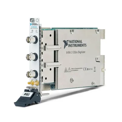

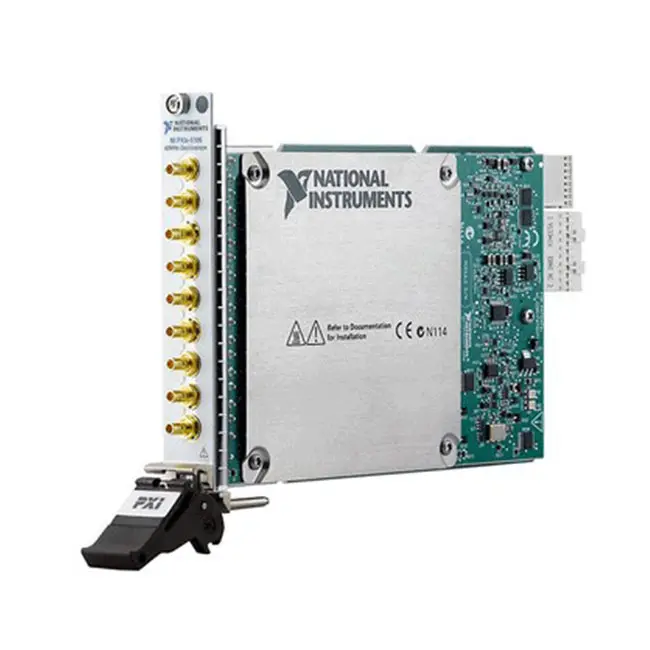
PXI-5110 / PXIe-5110 100 MHz PXI Oscilloscope
Земля PXIe-5110, sometimes searched for as the PXI-5110, is a two-channel PXI Express oscilloscope designed for automated electronic testing, waveform acquisition and time-domain signal analysis. It provides 100 MHz analog bandwidth, 8-bit vertical resolution and a maximum time-interleaved sample rate of 1 GS/s.
The PXIe-5110 combines flexible voltage ranges, selectable 50 Ω and 1 MΩ input impedance, AC/DC coupling, deep onboard memory and advanced triggering in a compact one-slot PXI Express module. It is suitable for production testing, electronic design validation, pulse measurements, power-electronics testing and synchronized multi-instrument PXI systems.
Four ordering configurations are available, combining either 64 MB or 512 MB of onboard memory with optional CableSense technology. CableSense-compatible versions can help identify signal-path faults, impedance changes and cable discontinuities within an automated test system.
Important PXI-5110 Model Identification
NI officially identifies this oscilloscope as the PXIe-5110. Although it is frequently listed or searched online as PXI-5110, the module uses a PXI Express Gen 1 ×4 interface and must be installed in a PXI Express peripheral slot, PXI Express hybrid peripheral slot or compatible PXI Express system timing slot.
It is not a conventional PCI-based PXI module. Verify the complete model number and chassis slot compatibility before purchasing or replacing an existing oscilloscope module.
Key Features of the PXIe-5110
- Two simultaneously sampled analog input channels
- 100 MHz analog input bandwidth
- 1 GS/s maximum time-interleaved sample rate
- 500 MS/s maximum real-time sample rate
- 8-bit analog input resolution
- 64 MB or 512 MB onboard waveform memory
- Up to 100,000 records with the 512 MB version
- 40 mVpk-pk to 40 Vpk-pk selectable input ranges
- 50 Ω and 1 MΩ selectable input impedance
- AC and DC input coupling
- 20 MHz bandwidth-limiting noise filter
- Edge, glitch, runt, width and window triggering
- Four bidirectional front-panel PFI connections
- Optional CableSense signal-path diagnostics
- NI-TClk multi-instrument synchronization
- Software-controlled self-calibration
- NI-SCOPE and InstrumentStudio support
- One-slot 3U PXI Express module
PXIe-5110 Technical Specifications
| Product Model | PXIe-5110 |
|---|---|
| Alternative Search Name | PXI-5110 |
| Product Type | PXI Express oscilloscope and high-speed digitizer |
| Number of Analog Channels | 2, simultaneously sampled |
| Input Configuration | Referenced single-ended |
| Analog Input Connectors | 2 × ground-referenced female BNC |
| Analog Bandwidth | 100 MHz |
| Maximum Real-Time Sample Rate | 500 MS/s |
| Maximum Time-Interleaved Sample Rate | 1 GS/s, single-channel operation |
| Real-Time Sample-Rate Range | 7.63 kS/s to 500 MS/s |
| Analog Input Resolution | 8 bits |
| Input Impedance | 50 Ω or 1 MΩ |
| Input Capacitance | 16 pF with 1 MΩ input |
| Input Coupling | AC or DC |
| Full-Scale Input Ranges | 0.04 Vpk-pk to 40 Vpk-pk, depending on impedance |
| Maximum 50 Ω Input Range | 10 Vpk-pk |
| Maximum 1 MΩ Input Range | 40 Vpk-pk |
| Maximum 50 Ω Input Overload | Peak voltage not exceeding 7 V |
| Maximum 1 MΩ Input Overload | Peak voltage not exceeding 250 VDC, frequency derating applies |
| Bandwidth-Limiting Filter | 20 MHz noise filter |
| AC-Coupling Cutoff Frequency | 10 Hz |
| Typical RMS Noise | 0.3% of full scale |
| Channel Crosstalk | Less than -65 dB at input frequencies up to 100 MHz |
| Spurious-Free Dynamic Range | -50 dBc under specified conditions |
| Total Harmonic Distortion | -50 dBc under specified conditions |
| Onboard Memory Options | 64 MB or 512 MB, shared between enabled channels |
| Maximum Number of Records | 100,000 with the 512 MB option |
| Timebase Frequency | 500 MHz |
| Timebase Accuracy | ±50 ppm |
| Sample Clock Jitter | 2 ps RMS |
| Channel-to-Channel Skew | Less than 100 ps |
| PFI Connections | 4 × bidirectional front-panel HD-BNC |
| Probe Compensation Output | 0 V to 5 V, 1 kHz square wave |
| Calibration Interval | 2 years |
| Recommended Warm-Up Time | 15 minutes |
| Driver | NI-SCOPE |
| Шинный интерфейс | PXI Express Gen 1 ×4 |
| Compatible Slots | PXI Express peripheral or hybrid peripheral slots |
| Module Format | 3U, one-slot PXI Express module |
| Dimensions | 2.0 × 13.0 × 21.6 cm |
| Weight | 380 g |
| Operating Temperature | 0°C to 55°C |
| Storage Temperature | -40°C to 71°C |
| Operating Humidity | 10% to 90%, noncondensing |
PXIe-5110 Part Numbers
| Part Number | Memory | CableSense | Описание |
|---|---|---|---|
| 785767-11 | 64 MB | Да | PXIe-5110 oscilloscope with CableSense technology |
| 785768-11 | 512 MB | Да | PXIe-5110 oscilloscope with deep memory and CableSense technology |
| 785767-01 | 64 MB | No | PXIe-5110 oscilloscope with standard waveform memory |
| 785768-01 | 512 MB | No | PXIe-5110 oscilloscope with extended waveform memory |
Confirm the required memory capacity and CableSense option before ordering. Products with similar model names can have different memory, diagnostic and pricing configurations.
PXIe-5110 Compatible Accessories
| Accessory | Purpose |
|---|---|
| 50 Ω BNC coaxial cable | Connects matched signal sources and test fixtures to CH 0 or CH 1 |
| Passive oscilloscope probe | Measures higher-impedance circuits through the 1 MΩ input |
| 50 Ω BNC terminator | Provides external termination when required by the measurement setup |
| HD-BNC trigger cable | Connects external trigger and event signals to PFI 0 through PFI 3 |
| BNC adapters and attenuators | Supports fixture integration and signal-level adjustment |
| Compatible PXI Express chassis | Provides power, cooling, triggering and the PXI Express interface |
Select cables, probes and attenuators according to the required bandwidth, impedance, voltage rating and connector type. A cable or probe with insufficient bandwidth can limit the performance of the complete measurement path.
Two Simultaneously Sampled Channels
The PXIe-5110 provides two analog input channels that can acquire signals simultaneously. Simultaneous sampling is important when comparing timing, phase, propagation delay or transient behavior between two related signals.
Typical examples include comparing a power-converter input and output, measuring a command signal and system response, or observing clock and data signals at the same point in a test sequence.
Channel-to-channel skew is less than 100 ps under the specified conditions, supporting accurate timing comparisons between the two input paths.
100 MHz Analog Bandwidth
The PXIe-5110 provides 100 MHz analog bandwidth with either 50 Ω or 1 MΩ input impedance. This bandwidth supports many electronic validation and automated test applications involving pulse signals, communication interfaces, power electronics and moderate-frequency analog waveforms.
System bandwidth is also affected by probes, cables, adapters, fixtures, source impedance and termination. Every component in the signal path should provide sufficient bandwidth for the signal being measured.
1 GS/s Maximum Sampling
The oscilloscope reaches a maximum sample rate of 1 GS/s in time-interleaved sampling mode. This mode uses a single input channel and interleaves the converter resources to provide the highest available sampling rate.
For normal simultaneous acquisition on both channels, the maximum real-time sample rate is 500 MS/s. Lower sample rates are generated through decimation from the 500 MS/s clock.
Choose the sample rate according to the signal bandwidth, transient duration and required record length. Higher sample rates provide greater time resolution but consume onboard memory more rapidly.
8-Bit Vertical Resolution
The PXIe-5110 uses an 8-bit analog-to-digital converter architecture. Each selected full-scale range is divided into 256 nominal digitization levels.
Selecting the smallest suitable input range improves the amount of ADC resolution applied to the measured waveform. If the selected range is much larger than the signal, the waveform uses only a small portion of the available digitizer codes.
For applications prioritizing greater amplitude resolution rather than maximum sampling speed, consider a 12-bit or 14-bit PXI oscilloscope.
Flexible Input Ranges
The PXIe-5110 provides full-scale input ranges from 40 mVpk-pk to 10 Vpk-pk with 50 Ω impedance. With the 1 MΩ input selected, ranges extend from 40 mVpk-pk to 40 Vpk-pk.
Programmable vertical offset allows the digitizer range to be positioned around a DC operating level. This can help capture relatively small variations superimposed on a larger DC voltage, provided the signal and offset remain within the applicable operating limits.
50 Ω and 1 MΩ Input Impedance
The selectable 50 Ω input is suitable for impedance-matched signal generators, RF signal paths and coaxial test systems. Correct 50 Ω termination reduces reflections and helps maintain signal integrity.
The 1 MΩ input is appropriate for general oscilloscope measurements and passive probes where the instrument should place a lighter load on the circuit. Input capacitance and probe capacitance must still be considered when measuring fast or high-impedance signals.
Never connect a voltage that exceeds the overload specification. The permitted 1 MΩ overload decreases with increasing signal frequency.
AC and DC Input Coupling
DC coupling passes both the DC component and changing portion of the input waveform. It is normally selected when the absolute signal voltage or DC operating point is important.
AC coupling blocks the DC component and allows the oscilloscope to examine AC variations around a large DC level. The AC-coupling cutoff frequency is 10 Hz, so very-low-frequency waveform content can be attenuated.
20 MHz Noise Filter
A software-selectable 20 MHz bandwidth-limiting filter can reduce high-frequency noise when the signal of interest occupies a lower frequency range.
Enabling the filter can improve waveform stability and effective resolution for slower signals. It should be disabled when the measurement requires the full 100 MHz bandwidth or contains important frequency components above 20 MHz.
64 MB and 512 MB Waveform Memory
The PXIe-5110 is available with either 64 MB or 512 MB of onboard memory. Memory is shared between all enabled channels.
Deep onboard memory allows the oscilloscope to capture longer time intervals at high sample rates. The 512 MB configuration is preferable for long records, segmented acquisitions and applications that capture many triggered events before transferring the data to the controller.
Multi-Record Acquisition
The 512 MB PXIe-5110 can store as many as 100,000 records, depending on record length and enabled channels. Multi-record acquisition captures a series of triggered waveform segments without storing unnecessary data between events.
This capability is useful for pulse testing, intermittent-fault capture, serial-bus event analysis and production systems that must record multiple DUT events efficiently.
Advanced Triggering
The PXIe-5110 supports edge, glitch, hysteresis, runt, width, window, digital, immediate and software triggers. Trigger sources include CH 0, CH 1, PFI 0 through PFI 3 and PXI trigger lines 0 through 7.
Flexible triggering helps isolate specific waveform events such as:
- Rising or falling voltage transitions
- Pulses shorter or longer than expected
- Signals entering or leaving a voltage window
- Incomplete digital pulses and runt signals
- Intermittent glitches
- Externally synchronized test events
Front-Panel PFI Connections
Four bidirectional programmable function interface connections are provided through front-panel HD-BNC connectors. Each PFI line can accept a digital trigger or route an acquisition event to another instrument or test-system component.
The PFI connections use 3.3 V CMOS logic, accept recommended input levels from 0 V to 3.3 V and are tolerant of inputs up to 5 V. The maximum output-event frequency is 50 MHz.
CableSense Technology
Part numbers ending in the CableSense configuration provide signal-path diagnostic capability. CableSense sends a controlled pulse through a connected 50 Ω path and analyzes reflections produced by impedance changes.
This allows the test system to detect and locate certain open circuits, shorts, loose connections or discontinuities in RF cables, adapters, switching paths and fixtures.
CableSense can reduce troubleshooting time in production systems where cable failures may otherwise appear to be DUT failures. Its actual diagnostic range and accuracy depend on the connected cable and signal-path characteristics.
Probe Compensation Output
The front panel provides a 0 V to 5 V, 1 kHz square-wave output for passive probe compensation. Adjusting a compatible passive probe against this reference helps match the probe capacitance to the oscilloscope input.
An incorrectly compensated probe can produce overshoot, rounded edges or amplitude errors when measuring square waves and other fast signals.
NI-TClk Synchronization
NI-TClk allows multiple supported PXI instruments to share reference clocks and triggers through the PXI chassis backplane. This helps align acquisitions between multiple PXIe-5110 modules or between the oscilloscope and other compatible PXI instruments.
With identical modules in the same chassis, NI specifies 200 ps peak-to-peak skew without manual adjustment. Manual adjustment can reduce average skew to approximately 10 ps under the specified conditions.
Multi-instrument synchronization is useful for mixed-signal testing, multi-channel waveform acquisition, stimulus-and-response measurements and systems requiring more than two oscilloscope channels.
Self-Calibration
Software-controlled self-calibration corrects gain, offset, ADC-interleaving and intermodule synchronization errors. NI recommends allowing the module to warm up for at least 15 minutes before self-calibration.
Self-calibration should be performed after the module is power-cycled or after the controller restarts or resumes from sleep. External calibration has a recommended interval of two years.
NI-SCOPE Software Support
The PXIe-5110 is controlled through the NI-SCOPE instrument driver. NI-SCOPE provides configuration, acquisition, measurement, synchronization and calibration functions for automated oscilloscope applications.
Programming interfaces and examples are available for LabVIEW, LabWindows/CVI, Measurement Studio, Microsoft Visual C/C++ and .NET languages such as C# and Visual Basic.
InstrumentStudio Integration
InstrumentStudio provides an interactive soft front panel for configuring the PXIe-5110 and viewing acquired waveforms without initially creating a custom program.
Engineers can use InstrumentStudio during system setup, troubleshooting and measurement development. A verified configuration can then be transferred into an automated LabVIEW, C# or TestStand workflow.
Typical PXIe-5110 Applications
- Automated electronic test equipment
- Production functional testing
- Валидация электронного дизайна
- Power-electronics waveform measurement
- Pulse-width and rise-time analysis
- Clock and timing measurements
- Transient capture
- Communication-interface testing
- Component characterization
- Research and laboratory measurement
- Multi-channel synchronized acquisition
- Intermittent-fault detection
- Cable and fixture diagnostics
- Hardware-in-the-loop testing
Production Test Applications
The PXIe-5110 can acquire waveforms automatically as part of a production test sequence. Software can configure the vertical range, sample rate, trigger and record length for each product or test step.
Captured data can be analyzed for amplitude, frequency, rise time, pulse width, overshoot and other pass/fail parameters. Multi-record acquisition can improve efficiency when multiple events must be captured from each DUT.
Power-Electronics Testing
The oscilloscope can measure control signals, gate-drive waveforms, converter timing and other signals within its voltage and bandwidth limits. Its two simultaneous channels allow related input and output signals to be compared.
Appropriate differential probes, high-voltage probes and isolation equipment are required when a measurement is not referenced to the oscilloscope ground or exceeds the direct-input limits. The PXIe-5110 inputs are ground-referenced and must not be connected directly across floating high-energy circuits.
Pulse and Transient Measurements
The 1 GS/s maximum sampling rate and advanced trigger functions support measurement of short pulses and transient events. Glitch, runt and width triggers can isolate abnormal pulses that are difficult to capture with a basic edge trigger.
Deep memory allows the instrument to record activity before and after a trigger while maintaining a relatively high sample rate.
Automated Cable Diagnostics
CableSense-equipped versions can be used in automated test stations containing coaxial cables, adapters, RF switches and fixture interconnects. A diagnostic sequence can establish a baseline for a known-good path and detect changes as the system ages.
This helps maintenance teams distinguish a signal-path failure from an instrument or DUT failure and can reduce production-system downtime.
PXIe-5110 Measurement Workflow
Step 1: Select the Input Configuration
Choose CH 0 or CH 1, set the input impedance and select AC or DC coupling according to the signal source.
Step 2: Configure the Vertical Range
Select the smallest range that contains the complete waveform without clipping. Apply vertical offset when the signal is centered around a DC level.
Step 3: Set the Sample Rate and Record Length
Choose a sample rate high enough for the required time resolution and a record length that covers the entire event.
Step 4: Configure the Trigger
Select the appropriate trigger source and type. Set the trigger level, slope, window, pulse-width condition or other event criteria.
Step 5: Acquire the Waveform
Initiate the acquisition using InstrumentStudio or NI-SCOPE and retrieve the waveform after the trigger condition occurs.
Step 6: Analyze and Store Results
Calculate the required time-domain or frequency-domain measurements and save the waveform or pass/fail result.
PXIe-5110 Troubleshooting
The module is not detected in NI MAX
Confirm that the module is fully inserted into a compatible PXI Express or hybrid peripheral slot. Check chassis power, controller communication and NI-SCOPE installation, then refresh the hardware list in NI MAX.
No waveform is displayed
Verify the BNC connection, selected input channel, impedance, coupling and trigger configuration. An incorrect trigger level can prevent the acquisition from completing even when a signal is present.
The waveform is clipped
Select a larger input range or adjust the vertical offset. Confirm that the signal remains below the maximum overload rating for the selected input impedance.
The waveform amplitude is incorrect
Check the 50 Ω or 1 MΩ input setting, probe attenuation, cable termination and software probe-scaling configuration. A double-terminated 50 Ω source or incorrect probe factor can produce substantial amplitude error.
The waveform contains excessive noise
Use a smaller vertical range, improve grounding and shielding, shorten the signal cable and enable the 20 MHz filter when the signal bandwidth permits it.
The 1 GS/s rate is unavailable
Time-interleaved 1 GS/s acquisition is available for single-channel operation. Disable the second channel or use 500 MS/s when simultaneous acquisition is required.
The maximum record length is lower than expected
Onboard memory is shared between enabled channels. Disable unused channels, reduce the number of records or verify whether the module has the 64 MB or 512 MB memory option.
Channels are not aligned correctly
Run self-calibration after the warm-up period. For multiple modules, configure NI-TClk synchronization and verify that the instruments use compatible reference clocks and trigger settings.
CableSense does not appear in software
Confirm that the installed PXIe-5110 part number includes CableSense and that a compatible NI-SCOPE version is installed. Standard -01 configurations do not provide CableSense support.
PXIe-5110 Comparison with Similar PXI Oscilloscopes
| Модель | Primary Configuration | Best Suited For |
|---|---|---|
| ПХИ-5105 | 8 channels, 60 MHz bandwidth, 60 MS/s | Higher channel density at moderate sampling speed |
| PXIe-5110 | 2 channels, 100 MHz, up to 1 GS/s, 8-bit | Cost-effective high-speed automated measurements |
| PXI-5114 | 2 channels, 125 MHz, 250 MS/s, 8-bit | Existing PXI systems requiring a traditional PXI interface |
| PXI-5122 | 2 channels, 100 MHz, 100 MS/s, 14-bit | Measurements prioritizing vertical resolution |
| PXI-5154 | 2 channels, 1 GHz, up to 2 GS/s, 8-bit | Higher-bandwidth waveform acquisition |
| PXIe-5185 | Multi-gigahertz PXI Express oscilloscope | High-speed serial, RF and wideband testing |
PXIe-5110 vs PXI-5105
Земля ПХИ-5105 provides eight input channels with 60 MHz bandwidth and a maximum sampling rate of 60 MS/s. The PXIe-5110 provides only two channels but offers 100 MHz bandwidth and sampling up to 1 GS/s.
Choose the PXI-5105 when channel density is the primary requirement. Choose the PXIe-5110 when greater time resolution, faster sampling and advanced PXI Express synchronization are more important.
PXIe-5110 vs PXI-5122
Земля PXI-5122 provides 14-bit resolution and 100 MHz bandwidth with a lower maximum real-time sampling rate. The PXIe-5110 provides 8-bit resolution but offers sampling up to 1 GS/s.
Select the PXI-5122 for measurements requiring greater amplitude resolution and dynamic range. Select the PXIe-5110 for faster waveform sampling, transient capture and high-throughput automated testing.
PXIe-5110 vs PXI-5154
Земля PXI-5154 provides substantially higher analog bandwidth for measuring faster signals. The PXIe-5110 is a more economical choice for applications that remain within 100 MHz.
The required signal bandwidth, rise time, sampling rate, memory and chassis interface should be evaluated before selecting between the two instruments.
Recommended Related Products
- PXI-5105 8-Channel PXI Oscilloscope
- PXI-5114 125 MHz PXI Oscilloscope
- PXI-5122 14-Bit PXI Oscilloscope
- PXI-5124 12-Bit PXI Oscilloscope
- PXI-5142 PXI Oscilloscope
- PXI-5152 High-Speed Oscilloscope
- PXI-5153 High-Speed Oscilloscope
- PXI-5154 1 GHz PXI Oscilloscope
- PXIe-5185 High-Speed PXI Express Oscilloscope
- View More NI PXI and PXI Express Modules
Selecting the Right PXIe-5110 Configuration
Choose a 64 MB version for shorter waveform records and conventional automated measurements. Select the 512 MB version when the application requires long high-speed records, extensive pretrigger data or a large number of segmented acquisitions.
Select a CableSense-compatible part number when the test system includes signal paths that require automated cable and fixture diagnostics. A standard version may be sufficient when CableSense is not required.
Why Choose the PXIe-5110?
- Provides two simultaneously sampled channels
- Delivers 100 MHz analog bandwidth
- Supports sampling rates up to 1 GS/s
- Offers selectable 50 Ω and 1 MΩ inputs
- Provides AC/DC coupling and a 20 MHz filter
- Supports 64 MB or 512 MB waveform memory
- Provides advanced pulse and window triggers
- Supports optional CableSense diagnostics
- Synchronizes with other PXI instruments through NI-TClk
- Integrates with NI-SCOPE and InstrumentStudio
- Occupies only one PXI Express chassis slot
Frequently Asked Questions
Is the official model PXI-5110 or PXIe-5110?
The official NI model is PXIe-5110. PXI-5110 is commonly used as a shortened search term, but the hardware uses a PXI Express interface.
What is the bandwidth of the PXIe-5110?
The oscilloscope provides 100 MHz analog bandwidth with either 50 Ω or 1 MΩ input impedance.
What is its maximum sample rate?
The maximum sample rate is 1 GS/s in single-channel time-interleaved sampling mode. The maximum real-time rate for simultaneous two-channel acquisition is 500 MS/s.
How many analog input channels are provided?
The PXIe-5110 provides two simultaneously sampled, referenced single-ended analog input channels.
What is the analog input resolution?
The analog-to-digital converter provides 8-bit vertical resolution.
Which input impedances are supported?
Each analog input can be configured for 50 Ω or 1 MΩ impedance.
What memory options are available?
The PXIe-5110 is available with 64 MB or 512 MB of onboard waveform memory. Memory is shared between enabled channels.
What is CableSense?
CableSense is an optional signal-path diagnostic technology that uses reflected pulses to detect and locate certain impedance changes, connection faults and cable discontinuities.
Does every PXIe-5110 include CableSense?
No. Part numbers 785767-11 and 785768-11 include CableSense. Part numbers 785767-01 and 785768-01 do not include it.
Can the PXIe-5110 be installed in a traditional PXI slot?
No. It requires a PXI Express peripheral slot, compatible hybrid peripheral slot or supported PXI Express system timing slot.
Which software controls the PXIe-5110?
The PXIe-5110 uses the NI-SCOPE driver and can be controlled interactively through InstrumentStudio or programmed with LabVIEW, C/C++, C# and other supported environments.
What is the recommended calibration interval?
NI specifies a two-year external calibration interval. The module also supports software-controlled self-calibration after a 15-minute warm-up.
What are the PXIe-5110 part numbers?
The available part numbers are 785767-11, 785768-11, 785767-01 и 785768-01. They differ by onboard memory and CableSense support.
Request a Quote for the PXIe-5110
Contact us for current availability, lead time and project pricing for the PXIe-5110 100 MHz, 1 GS/s, 8-Bit PXI Oscilloscope. Please provide the required memory capacity and CableSense configuration when requesting a quotation. We can also help identify compatible probes, BNC cables, PXI Express chassis and related NI oscilloscopes for your automated test system.















