




Показаны все (13)

Фильтр по цене
Фильтровать по брендам

- Национальные инструменты
- Системы PXI
- PXI Шасси
- PXI Контроллер
- Модули PXI
- PXI Semiconductor Test
- PXI FPGA and RIO Modules
- PXI MXI Interfaces
- PXI Programmable Power Supplies & SMU
- PXI Sensor Measurements
- Генераторы сигналов PXI
- PXI Vision
- Сбор данных PXI
- Осциллографы/Цифровые преобразователи PXI
- PXI Счетчики/Таймеры
- PXI РЧ и беспроводное тестирование
- PXI GPIB, Ethernet and VXI
- PXI-коммутаторы
- Цифровые мультиметры PXI
- Цифровой ввод-вывод PXI
- Промышленная связь PXI
- Динамический анализ сигналов PXI
- Передача данных PXI
- CompactDAQ Systems
- CompactRIO Systems
- PCI Modules
- USB Devices
- Устройство программно-определяемого радио USRP
- Системы PXI
- ключи
- ТекТроникс


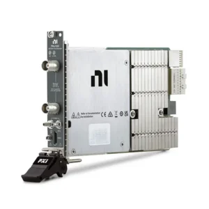


NI PXI Oscilloscopes and Digitizers
NI PXI Oscilloscopes and Digitizers are modular instruments for capturing, recording and analyzing time-domain electrical signals in automated PXI and PXI Express test systems. Compared with general-purpose data acquisition hardware, digitizers are optimized for higher analog bandwidth, faster sample rates, deeper waveform records, flexible input front ends and advanced triggering.
Select the correct PXI digitizer by comparing analog bandwidth, real-time sample rate, vertical resolution, channel count, input range, impedance, record length, triggering, synchronization and sustained data-transfer requirements. Chassis slot compatibility, controller performance, probes, cables, software and calibration must also be evaluated as part of the complete measurement system.
How PXI Oscilloscopes and Digitizers Work
A PXI digitizer converts an analog input waveform into a sequence of digital samples. It is installed in a compatible PXI or PXI Express chassis and controlled by an embedded controller or remote computer. Waveforms can be displayed, analyzed, transferred to system memory, stored to disk or evaluated automatically against test limits.
Unlike a standalone oscilloscope with an integrated display and front-panel controls, a PXI oscilloscope is software controlled. This makes it suitable for automated systems that combine waveform acquisition with signal generation, switching, programmable power, digital instruments and synchronized timing resources.
PXI Oscilloscope Compared with PXI Digitizer
| Selection Factor | PXI Oscilloscope Workflow | PXI Digitizer Workflow |
|---|---|---|
| Primary Use | Viewing, debugging and measuring time-domain waveforms | Programmatic waveform acquisition and automated processing |
| Typical Environment | Engineering validation and design characterization | ATE, production test, monitoring and automated research |
| Operation | Oscilloscope-style soft front panel and measurements | Driver API, waveform transfer and custom analysis |
| Системная интеграция | Can be synchronized with other PXI instruments | Frequently integrated into multidevice test sequences |
| Data Handling | Finite records and interactive analysis | Finite records, repeated acquisition or continuous streaming |
The terms are often used together because the underlying hardware is similar. Selection should be based on bandwidth, sample rate, resolution, memory, triggering and software requirements rather than the word “oscilloscope” or “digitizer” in the product name.
Representative NI PXI Oscilloscope and Digitizer Models
| Модель | Unique Category | Core Architecture | Best Fit |
|---|---|---|---|
| PXI-5922 | Flexible-Resolution Precision Digitizer | Two-channel architecture with resolution up to 24 bits, sampling up to 15 MS/s and bandwidth up to 6 MHz | Low-noise waveform measurement, spectral analysis and precision electronic characterization |
| PXIe-5105 | High-Density Moderate-Speed Digitizer | Eight simultaneously sampled, 12-bit channels with rates and bandwidth up to 60 MS/s and 60 MHz | Multichannel transient capture, power systems and synchronized waveform recording |
| PXIe-5110 | General-Purpose 1 GS/s Oscilloscope | Two channels sampling at up to 1 GS/s with configurable coupling, impedance and voltage ranges | Automated electronic validation, pulse measurement and production test |
| PXIe-5111 | High-Sample-Rate Dual-Channel Oscilloscope | Two-channel architecture with sampling rates up to 3 GS/s and programmable input settings | Fast transient, edge and timing measurements requiring greater sample density |
| PXIe-5114 | Cost-Optimized Mid-Speed Oscilloscope | Two channels sampling at up to 250 MS/s with configurable coupling, impedance, range and filtering | General waveform capture where moderate speed and automated operation are required |
| PXIe-5122 | High-Resolution Spectral Digitizer | Two-channel high-resolution acquisition with strong dynamic performance and flexible input configuration | Spectral measurements, communications analysis and precision waveform characterization |
| PXIe-5162 | High-Speed Wideband Digitizer | Two- or four-channel architecture with sampling rates up to 5 GS/s | Wideband signals, fast pulses and high-throughput automated test |
| PXIe-5164 | High-Resolution Wideband Oscilloscope | Two 14-bit channels with 400 MHz bandwidth and sampling rates up to 1 GS/s | Power electronics, high-fidelity transient capture and mixed speed-resolution requirements |
| PXIe-5171 | High-Density Advanced Synchronization Oscilloscope | Eight simultaneously sampled channels with flexible coupling and voltage-range settings | High-channel-count acquisition and synchronized multichannel test systems |
This table represents major digitizer architectures rather than every model or hardware revision. Verify the exact part number, memory option, connector, chassis requirement, driver support and calibration status before ordering.
How to Select a PXI Oscilloscope or Digitizer
1. Start with Analog Bandwidth
Analog bandwidth defines the frequency range that the input front end can acquire with useful amplitude fidelity. Select bandwidth from the highest-frequency content that must be measured, not only the signal’s repetition frequency.
Fast digital pulses contain harmonics well above their clock or repetition rate. When rise-time measurement is important, a first planning estimate is:
Oscilloscope rise time ≈ 0.35 ÷ analog bandwidth.
The digitizer should normally have a faster rise time than the signal being measured. The exact bandwidth margin depends on the permitted rise-time and amplitude error.
2. Determine the Required Sample Rate
Sample rate defines how frequently the waveform is converted into digital data. Higher sample rates provide more samples across pulses, edges and high-frequency cycles, improving time-domain representation and measurement flexibility.
Nyquist theory establishes a minimum rate above twice the highest signal frequency, but practical waveform measurements commonly require additional sample-rate margin for accurate shape, timing and transient analysis.
The highest available sample rate is not automatically the best choice. Increasing the sample rate also increases memory consumption, bus traffic, storage requirements and processing workload.
3. Evaluate Vertical Resolution and Dynamic Performance
Vertical resolution determines the number of discrete amplitude levels available from the analog-to-digital converter. Higher resolution can improve the ability to distinguish small changes, but nominal ADC bits do not by themselves define measurement quality.
Also compare:
- Effective number of bits
- Signal-to-noise ratio
- Spurious-free dynamic range
- Total harmonic distortion
- DC gain and offset accuracy
- Input noise and range
A high-resolution digitizer such as the PXI-5922 may be preferable for precision and spectral measurements, while a higher-speed model may be more appropriate for fast edges and wideband transients.
4. Select the Number of Channels
Channel count should reflect the signals that must be captured at the same time. Typical multichannel applications include power-converter inputs and outputs, clock and data comparison, multiphase electrical systems, sensor arrays and parallel DUT testing.
When phase or time relationships are important, confirm that channels are sampled simultaneously. Also review channel-to-channel skew and whether all channels retain full performance when enabled.
5. Match the Input Range to the Signal
Select an input range that accommodates the expected waveform, DC offset, noise and transient overshoot. An unnecessarily wide range reduces the useful amplitude resolution, while an undersized range can cause clipping or overload.
Check whether the required range is supported with the selected input impedance and coupling mode. Maximum safe input and measurable full-scale range are separate specifications.
6. Confirm Input Impedance and Coupling
Common digitizer input configurations include 50 Ω and 1 MΩ impedance. A 50 Ω input is commonly used for terminated coaxial signal paths, while a 1 MΩ input is appropriate for compatible passive probes and higher-impedance sources.
Incorrect termination can change signal amplitude, introduce reflections or load the circuit being tested. Confirm whether the application requires AC or DC coupling and whether coupling options vary by input impedance or voltage range.
7. Calculate Record Length and Onboard Memory
Record length determines how long a waveform can be captured at the selected sample rate:
Required samples per channel = sample rate × acquisition duration.
Approximate waveform memory can be calculated as:
Memory = samples per channel × active channels × stored bytes per sample.
Use the transferred data width rather than only the ADC resolution. A 14-bit converter may transfer each sample in a 16-bit or wider data format.
Long records are useful for:
- Power-up and shutdown sequences
- Communication bursts
- Rare transient events
- Automated fault capture
- Intermittent production failures
- Long-duration waveform analysis
8. Review Triggering Requirements
Triggering determines which event initiates or qualifies waveform acquisition. Define the event of interest and confirm the required trigger source, level, slope, coupling and timing behavior.
Possible requirements include:
- Analog edge triggering
- Window or hysteresis triggering
- External digital triggering
- Software triggering
- PXI backplane trigger routing
- Pre-trigger and post-trigger acquisition
- Reference or stop triggering
- Multi-instrument synchronized triggering
Trigger performance should be considered together with the DUT control signals, stimulus generator, switch system and test sequence.
9. Determine Whether Segmented Acquisition Is Needed
Segmented or multirecord acquisition captures multiple triggered events while omitting unnecessary idle time between them. This can use onboard memory more efficiently and increase test throughput for repetitive pulses, packet bursts and production measurements.
Verify the minimum record length, rearm time, number of supported records and timestamp requirements for the selected model.
10. Calculate Continuous Data Throughput
High-speed digitizers can generate large data volumes. For continuous or repeated acquisition, estimate the payload rate:
Data rate = active channels × sample rate × transferred bytes per sample.
For example, two channels transferring two bytes per sample at 1 GS/s produce a theoretical payload of 4 GB/s before protocol, driver and file-system overhead.
The complete path must support the required sustained rate:
- Digitizer acquisition engine
- Module PCIe interface
- PXIe peripheral slot
- Chassis switch and backplane segment
- Controller or remote link
- System memory
- Storage device
- Analysis and display software
Acquiring a finite record into onboard memory is different from continuously streaming at the maximum sample rate. A module may capture at full speed for a limited record even when the chassis, controller or storage system cannot sustain that rate indefinitely.
Bandwidth, Sample Rate and Resolution Tradeoffs
| Priority | Architecture to Consider | Типичные применения |
|---|---|---|
| Maximum waveform speed | High-bandwidth, multi-GS/s digitizer | Fast pulses, serial signals and wideband transients |
| Amplitude detail | High-resolution or flexible-resolution digitizer | Spectral analysis, low-noise signals and precision characterization |
| More simultaneous channels | High-density synchronized digitizer | Power systems, parallel DUT testing and sensor arrays |
| Long acquisition duration | Deep-memory instrument or validated stream-to-disk system | Fault capture, signal recording and long test sequences |
| Application-specific processing | Reconfigurable or FPGA-accessible digitizer where supported | Inline processing, custom triggering and data reduction |
A single instrument does not necessarily maximize bandwidth, resolution, channel density and acquisition duration simultaneously. Selection should prioritize the characteristics that determine measurement quality for the actual signal.
Probes, Cables and Input Protection
The signal connection is part of the measurement system. Coaxial cables, probes, adapters, attenuation and external conditioning can limit bandwidth or introduce measurement error even when the digitizer itself meets the required specifications.
Confirm:
- Connector type and cable impedance
- Cable bandwidth and length
- Passive, active or differential probe requirements
- Probe attenuation and compensation
- Maximum input voltage and transient category
- Required DC blocking or external attenuation
- Grounding and common-mode voltage
Most PXI oscilloscope inputs are ground referenced and should not be treated as isolated inputs. Floating or high-common-mode measurements require an appropriate differential probe, isolation interface or other measurement method rated for the circuit.
PXI and PXIe Slot Compatibility
Traditional PXI digitizers use the PCI-based PXI backplane, while PXIe digitizers use PCI Express links. A traditional PXI module can be installed only in a compatible PXI or PXIe hybrid peripheral slot. A PXIe module requires a PXIe-compatible peripheral slot.
Before installation, verify:
- PXI, PXIe or hybrid slot type
- Available PCIe generation and lane width
- Bandwidth from the slot to the system controller
- Chassis power and cooling capability
- Number of adjacent slots required
- Front-panel cable clearance
High-speed digitizers should be positioned according to the chassis PCIe topology. Several modules installed behind the same chassis switch may share an upstream link and compete for bandwidth.
Multi-Digitizer Synchronization
Multiple digitizers can be synchronized when an application requires more channels than one module provides. A coordinated system may share reference clocks, sample-clock alignment and trigger signals through the PXI backplane.
NI-TClk supports synchronization of compatible modular instruments. The achievable alignment depends on the selected models, chassis, clock source, calibration, routing and software configuration.
Review:
- Reference clock frequency and accuracy
- Распределение триггеров
- Channel-to-channel and module-to-module skew
- Sample-clock phase alignment
- Jitter requirements
- Single-chassis or multichassis architecture
Using a common chassis does not automatically guarantee phase alignment. Synchronization must be configured and verified for the complete system.
PXI Digitizer Compared with Other Measurement Modules
| Instrument Type | Best Fit | Primary Selection Focus |
|---|---|---|
| PXI Oscilloscope/Digitizer | Fast waveform, pulse and transient acquisition | Bandwidth, sample rate, resolution, memory and triggering |
| PXI Data Acquisition Module | General voltage, sensor, digital and counter measurements | Channel count, input range, accuracy and multifunction I/O |
| PXI Dynamic Signal Module | Sound, vibration and high-dynamic-range measurements | IEPE conditioning, anti-alias filters, noise and phase matching |
| PXI RF Instrument | Calibrated RF generation, acquisition and modulation analysis | Frequency range, instantaneous bandwidth and RF performance |
| PXI Digital Instrument | Logic-level pattern acquisition and generation | Logic families, timing rate, direction and pattern memory |
Use PXI data acquisition modules when the application primarily requires slower multichannel voltage or sensor measurements. Review PXI RF and wireless instruments when calibrated RF conversion, modulation analysis or vector signal functionality is required.
Software and Automated Waveform Analysis
NI PXI oscilloscopes and digitizers commonly use NI-SCOPE for instrument configuration, triggering, waveform acquisition, synchronization and data transfer. InstrumentStudio provides an interactive environment for supported devices, while LabVIEW and other supported programming environments can be used to build automated applications.
A typical software stack may include:
- NI-SCOPE: Instrument driver and programmatic acquisition API
- InstrumentStudio: Interactive configuration and waveform viewing for supported instruments
- NI Measurement & Automation Explorer: Device recognition, self-test and configuration
- LabVIEW: Automated acquisition, processing and user-interface development
- TestStand: Production-test sequencing and result management
- NI-TClk: Synchronization of compatible modular instruments
Depending on the installed NI-SCOPE version, supported APIs may also be available for C/C++, .NET and Python. Confirm the exact model, operating system, driver version and programming environment before changing an established system.
Waveform Processing and Measurements
Digitizer data can be used for automated time-domain and frequency-domain analysis. Common measurements include:
- Peak, average and RMS voltage
- Frequency and period
- Rise time and fall time
- Pulse width and duty cycle
- Overshoot and undershoot
- Propagation delay and channel skew
- FFT and spectral analysis
- Total harmonic distortion
- Signal-to-noise ratio
- Custom waveform-mask and pass/fail testing
The selected sample rate, record length, windowing, averaging and filtering methods affect calculated results. Automated measurements should be validated against the required engineering method and test limits.
Calibration and Measurement Uncertainty
Digitizer accuracy can depend on gain, offset, input range, temperature, timebase, noise, distortion, probe accuracy and cable performance. Self-calibration can correct selected internal errors but does not replace scheduled external calibration where traceability is required.
A complete uncertainty review may include:
- Digitizer gain and offset accuracy
- Timebase accuracy and jitter
- Probe ratio accuracy
- Cable and adapter loss
- Input loading
- Noise and distortion
- Temperature drift
- External calibration uncertainty
Specify calibration documentation and required calibration interval before quotation when the hardware will be used in production, regulated or accredited laboratory environments.
Типичные применения
- Electronic design validation and debugging
- Semiconductor characterization and production test
- Power converter, inverter and motor-drive testing
- Power-rail and startup-sequence analysis
- Automotive ECU and power-electronics validation
- Pulse, timing and transient measurements
- Radar, avionics and defense signal acquisition
- IF and wideband signal recording
- Communications waveform analysis
- Multichannel scientific experiments
- Automated production test equipment
- Long-duration fault and event capture
Legacy PXI Digitizer Replacement
Replacing a legacy digitizer requires more than selecting a newer instrument with a higher sample rate. The original module may be tightly integrated with software, test fixtures, waveform limits and historical production data.
Compare the following before approving a replacement:
- PXI or PXIe slot compatibility
- Analog bandwidth and frequency response
- Sample rate and sampling behavior
- Vertical resolution and noise performance
- Input range, impedance and coupling
- Connector type and cable requirements
- Trigger modes and trigger routing
- Record length and onboard memory
- NI-SCOPE and operating-system support
- NI-TClk synchronization behavior
- Calibration procedure and measurement correlation
A newer model may provide better specifications but still require code changes, fixture modifications and system requalification. In validated production systems, maintaining the original model can sometimes present less engineering risk than changing the instrument architecture.
PXI Oscilloscope and Digitizer Procurement Guide
Provide the following information for model selection and quotation:
- Exact module model and part number if known
- Required analog bandwidth
- Required real-time sample rate
- Vertical resolution and dynamic-range requirements
- Number of simultaneous input channels
- Signal amplitude and expected transient level
- Required input impedance and coupling
- Acquisition duration and record length
- Single-record, multirecord or continuous-streaming operation
- Trigger and pre-trigger requirements
- Multi-module synchronization requirements
- Existing PXI/PXIe chassis and controller models
- Required probes, cables, adapters and attenuation
- Operating system, NI-SCOPE and application-software versions
- Calibration-documentation requirements
- Required quantity, product condition and destination
For pre-owned digitizers, request device-recognition, self-test and functional acquisition results. Verify the input connectors, trigger connector, backplane connector and module cooling surfaces for damage or contamination.
Часто задаваемые вопросы
What is the most important PXI digitizer specification?
There is no single most important specification. Analog bandwidth, sample rate, resolution, input range, channel count and acquisition duration must be evaluated together for the signal being measured.
Is a higher sample rate always better?
No. The sample rate must be sufficient for the signal bandwidth and required timing detail. Excessive sample rates increase memory, transfer, storage and processing requirements without necessarily improving the final measurement.
How much oscilloscope bandwidth do I need?
Bandwidth should be based on the highest-frequency signal content and required waveform fidelity. Fast pulses can require substantially more bandwidth than their repetition frequency suggests.
What is the difference between the PXI-5922 and PXIe-5164?
The PXI-5922 emphasizes flexible resolution and precision measurements, providing resolution up to 24 bits at lower bandwidth and sampling rates. The PXIe-5164 emphasizes faster wideband acquisition with two 14-bit channels, 400 MHz bandwidth and rates up to 1 GS/s.
When should I choose the PXIe-5105?
The PXIe-5105 is suitable when eight simultaneously sampled channels and moderate waveform bandwidth are more important than the highest possible sample rate.
Can multiple PXI digitizers be synchronized?
Yes, when the selected modules, chassis and software support the required clock and trigger architecture. NI-TClk can synchronize compatible modular instruments, but the complete configuration and achievable skew must be verified.
Can a PXI digitizer stream continuously at its maximum sample rate?
Not automatically. Continuous performance depends on the module interface, chassis topology, controller, system memory, storage and software. Maximum finite-record acquisition rate and maximum sustained streaming rate are different specifications.
Can I use a PXI digitizer for RF measurements?
A sufficiently fast digitizer can acquire compatible IF or wideband electrical signals. Calibrated RF measurements, frequency conversion, vector signal analysis and modulation testing may require dedicated PXI RF hardware.
Can a traditional PXI digitizer be installed in a PXIe chassis?
Only when the chassis provides a compatible hybrid peripheral slot. PXIe digitizers require PXIe-compatible slots. Check the exact module and chassis slot map before ordering.
Recommended PXI Oscilloscopes and Digitizers
Consider the PXI-5922 for flexible-resolution precision measurement, the PXIe-5105 for eight-channel simultaneous acquisition, the PXIe-5164 for 14-bit wideband waveform capture, or the PXIe-5171 for high-density synchronized acquisition.
Related NI PXI Solutions
Browse additional PXI and PXIe modules for complete automated test systems. Combine digitizers with PXI signal generators for stimulus-response testing or review the complete NI PXI systems category for chassis and controller options.
NI PXI Oscilloscopes and Digitizers from PXISOURCE
PXISOURCE supports engineers, system integrators and procurement teams with PXI digitizer selection, bandwidth and sample-rate review, chassis and controller compatibility, probe and cable matching, software verification and legacy-system replacement. Send the signal requirements, channel count, acquisition duration, chassis model and software version for a technically matched quotation.
Need help selecting an NI PXI oscilloscope or digitizer? Email sales@pxisource.com or contact PXISOURCE on WhatsApp.