






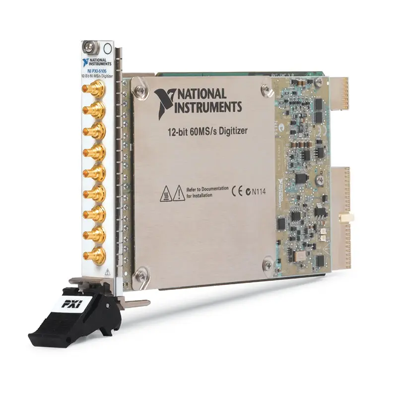
PXI-5105 8-Channel 60 MHz 60 MS/s 12-Bit Oscilloscope
Земля NI PXI-5105 is a high-density PXI oscilloscope and waveform digitizer designed for automated test, research and multichannel data-acquisition systems. It provides eight simultaneously sampled analog input channels, 12-bit vertical resolution, sampling rates up to 60 MS/s per channel and analog bandwidth up to 60 MHz.
Each input channel offers independently configurable voltage range, input impedance, coupling and filtering. Three onboard-memory configurations—16 MB, 128 MB and 512 MB—allow the PXI-5105 to capture multichannel transient events, long waveform records and repeated acquisitions.
Key Features of the PXI-5105
- Eight simultaneously sampled analog input channels
- 12-bit vertical resolution
- 60 MS/s real-time sampling rate per channel
- Up to 60 MHz analog bandwidth
- 50 Ω and 1 MΩ selectable input impedance
- AC or DC coupling on the 1 MΩ input path
- Five input ranges from 50 mVpp to 30 Vpp
- 16 MB, 128 MB or 512 MB onboard-memory options
- Memory shared across all enabled channels
- Analog edge, window, hysteresis and digital triggering
- Pretrigger and post-trigger waveform acquisition
- Multiple-record acquisition
- Onboard decimation and selectable filtering
- PFI connector for triggers and external clocks
- PXI backplane triggering and clock synchronization
- Multimodule synchronization capability
- SMB analog input connectors
- NI-SCOPE software support
- PXI Express hybrid-slot compatibility
- Single-slot 3U PXI module
PXI-5105 Technical Specifications
| Product Model | ПХИ-5105 |
|---|---|
| Product Type | PXI oscilloscope and high-speed digitizer |
| Analog Input Channels | 8 |
| Sampling Architecture | Simultaneous sampling on all channels |
| Vertical Resolution | 12 bits |
| Maximum Real-Time Sample Rate | 60 MS/s per channel |
| Maximum Analog Bandwidth | 60 MHz |
| Input Type | Referenced single-ended |
| Input Impedance | 50 Ω or 1 MΩ |
| 1 MΩ Input Capacitance | Approximately 50 pF |
| 50 Ω Input Ranges | 50 mVpp, 200 mVpp, 1 Vpp and 6 Vpp |
| 1 MΩ Input Ranges | 50 mVpp, 200 mVpp, 1 Vpp, 6 Vpp and 30 Vpp |
| Input Coupling | AC or DC on 1 MΩ; DC on 50 Ω |
| Available Filtering | Full bandwidth and selectable bandwidth-limiting or antialias filtering |
| Onboard Memory Options | 16 MB, 128 MB or 512 MB |
| Memory Allocation | Shared among enabled channels |
| Minimum Record Length | 1 sample, subject to memory-allocation requirements |
| Trigger Types | Analog edge, window, hysteresis, digital and software triggering |
| Trigger Sources | Analog channels, PFI and PXI trigger lines |
| Front-Panel Input Connectors | 8 × SMB |
| PFI Connector | 1 × SMB |
| Reference Clock | PXI 10 MHz reference or supported external reference clock |
| Reference Clock Frequency Range | 8 MHz to 65 MHz with supported division settings |
| Timebase Accuracy | ±25 ppm |
| Software Driver | NI-SCOPE |
| Шинный интерфейс | PXI; compatible with supported PXI Express hybrid slots |
| Module Format | 3U, one-slot PXI module |
| Maximum Power Consumption | Approximately 16.15 W |
| Operating Temperature | 0°C to 55°C |
| Storage Temperature | −40°C to 71°C |
| Dimensions | Approximately 21.6 × 2.0 × 13.0 cm |
| Weight | Approximately 474 g |
| Recommended External Calibration Interval | 2 years |
PXI-5105 Part Numbers and Memory Options
| Product Configuration | Part Number | Onboard Memory |
|---|---|---|
| PXI-5105 Base Memory | 779685-01 | 16 MB shared onboard memory |
| PXI-5105 Extended Memory | 779685-02 | 128 MB shared onboard memory |
| PXI-5105 Maximum Memory | 779685-03 | 512 MB shared onboard memory |
| SMB-to-BNC Cable | Configuration dependent | Connects an SMB input to BNC probes, fixtures or instruments |
| 50 Ω Coaxial Cable | Configuration dependent | Coaxial cable for terminated high-frequency signal measurements |
| Oscilloscope Probe | Configuration dependent | Passive or active probe selected according to voltage and bandwidth requirements |
The three PXI-5105 ordering configurations have the same principal channel count, sampling rate, resolution and bandwidth. Their primary difference is onboard acquisition memory. Confirm the required record length, number of enabled channels and number of acquisition records before selecting a part number.
Eight Simultaneously Sampled Channels
The PXI-5105 includes eight independent analog input channels that sample at the same time. Simultaneous sampling preserves the time and phase relationships among all eight signals without the channel-to-channel delay associated with multiplexed data-acquisition devices.
This architecture is useful for power electronics, multichannel sensor testing, transient recording, ultrasonic systems and applications that compare several signals during the same physical or electrical event.
60 MS/s Sampling on Every Channel
Each enabled channel can sample at rates up to 60 MS/s. The full rate remains available across all eight channels, allowing the module to acquire an aggregate of as many as 480 million samples per second.
The sample rate can be reduced through programmable decimation when the application requires a longer acquisition window or a lower data rate. Select a sample rate high enough to reproduce the signal bandwidth and transient details required by the analysis.
60 MHz Analog Bandwidth
The maximum 60 MHz analog bandwidth allows the PXI-5105 to capture fast electronic signals, modulated waveforms, pulses and other events extending beyond the range of ordinary multifunction DAQ modules.
Bandwidth depends on input impedance, selected voltage range and filtering. The complete measurement path—including probe, cable, fixture and termination—must also provide sufficient bandwidth.
12-Bit Vertical Resolution
The 12-bit ADC provides 4,096 theoretical quantization levels across the selected input range. Compared with a conventional 8-bit oscilloscope, the additional resolution helps distinguish smaller amplitude changes within larger signals.
Effective measurement performance depends on noise, linearity, signal frequency and the selected input range. Choose the smallest range that safely contains the waveform without clipping.
Independent Channel Configuration
Each channel provides independent control of its input range, impedance, coupling and filtering. This allows one PXI-5105 to measure signals with different amplitudes and source characteristics during the same acquisition.
For example, a test can simultaneously acquire a low-level sensor signal on a 200 mVpp range and a higher-voltage control signal on a 30 Vpp range.
50 Ω Input Path
The 50 Ω input path is intended for impedance-matched signal sources, RF-style signal chains and high-frequency electronic measurements. It minimizes reflections when used with 50 Ω coaxial cables and properly terminated sources.
The 50 Ω path provides ranges from 50 mVpp to 6 Vpp and is always DC coupled. Confirm that the source cannot apply excessive voltage or power to the termination.
1 MΩ High-Impedance Input Path
The 1 MΩ input path reduces loading on high-impedance sources and supports conventional oscilloscope probes. It provides input ranges from 50 mVpp to 30 Vpp and includes approximately 50 pF of input capacitance.
At higher frequencies, input capacitance and probe characteristics can affect the measured waveform. Use a compensated probe or suitable low-capacitance connection when signal integrity is important.
AC and DC Input Coupling
The 1 MΩ input path supports software-selectable AC and DC coupling. DC coupling preserves both the waveform and its DC offset, while AC coupling blocks the DC component and allows smaller time-varying signals to be measured on top of a larger DC level.
The 50 Ω path is DC coupled. When AC coupling is required with a terminated source, an appropriately rated external coupling network may be necessary.
Selectable Input Ranges
The PXI-5105 provides five full-scale input ranges on the 1 MΩ path: 50 mVpp, 200 mVpp, 1 Vpp, 6 Vpp and 30 Vpp. The 50 Ω path supports the same ranges except for 30 Vpp.
A smaller voltage range improves sensitivity but reduces the maximum allowable signal amplitude. Account for overshoot, noise and transient spikes when choosing the range.
Selectable Filtering
The module provides full-bandwidth operation and selectable filtering to reduce unwanted high-frequency content. Appropriate filtering can improve the signal-to-noise ratio and reduce aliasing when acquiring at lower sampling rates.
Filtering should be selected according to the frequency content that must be preserved. A bandwidth limit that is too low can attenuate pulse edges or remove valid high-frequency information.
Deep Onboard Acquisition Memory
The PXI-5105 is available with 16 MB, 128 MB or 512 MB of onboard memory. More memory permits longer waveform records, additional reference records and larger multirecord acquisitions.
Memory is shared across all enabled channels. Enabling fewer channels increases the memory available to each remaining channel, while enabling all eight divides the available memory among the complete channel set.
Pretrigger and Post-Trigger Acquisition
The acquisition memory operates as a circular buffer before a trigger occurs. This architecture allows the PXI-5105 to retain samples acquired before the trigger as well as the waveform that follows it.
Pretrigger data is useful when engineers must understand what happened immediately before a fault, threshold crossing or external event.
Multiple-Record Acquisition
Multiple-record mode captures a series of triggered waveform segments without storing long periods of irrelevant data between events. Each record can include its own pretrigger and post-trigger samples.
This improves test efficiency for repetitive pulses, serial transactions, switching events, ultrasonic echoes and other burst-oriented signals.
Advanced Triggering
The PXI-5105 supports analog edge, window and hysteresis triggering as well as digital and software triggers. Trigger level, slope, coupling and delay can be configured according to the acquisition requirement.
Window triggering detects when a signal enters or leaves a selected voltage band. Hysteresis helps prevent unstable triggering when a noisy signal remains near the threshold.
PFI Trigger and Clock Connector
The front-panel PFI 1 SMB connector is a multifunction digital connection. Depending on the software configuration, it can carry an external trigger, external sample clock, reference clock, trigger output or timebase output.
This connector helps synchronize the PXI-5105 with external instruments, devices under test and non-PXI timing sources.
PXI Backplane Synchronization
The module can use the PXI 10 MHz reference clock and PXI trigger lines for coordination with other instruments. The sample clock can be phase locked to a supported reference, improving repeatability across multiple modules.
Multimodule systems can expand the channel count while maintaining aligned sample clocks and trigger events. Signal propagation, cable delay and module-to-module skew should still be considered in precision phase measurements.
Multichannel Transient Recording
The eight-channel architecture is well suited for recording events that occur simultaneously at several test points. Typical examples include power-supply startup, circuit-breaker operation, ignition events, impact tests and synchronized sensor responses.
Deep onboard memory allows a transient event to be recorded at high sample rate for a longer duration than modules with shallow acquisition buffers.
Power Electronics Testing
The PXI-5105 can acquire gate-drive signals, control signals, current-shunt outputs and isolated voltage-probe outputs from inverters, converters and motor-control systems.
Suitable differential probes or isolated transducers are required when measuring floating or high-voltage circuits because the module inputs are referenced to chassis ground.
Ultrasonic and Nondestructive Testing
With 60 MHz bandwidth and 60 MS/s simultaneous sampling, the PXI-5105 can acquire ultrasonic and acoustic-emission signals within the applicable frequency range. Multiple channels can monitor several sensors or test locations during the same excitation event.
External preamplifiers, filters or impedance-matching circuits may be required depending on the transducer output and cable configuration.
Scientific and Research Measurements
The combination of eight channels, 12-bit resolution and deep memory is useful for laboratory experiments involving detectors, optical sensors, plasma diagnostics, combustion testing and other transient phenomena.
NI-SCOPE provides access to raw waveform data so researchers can implement custom filtering, spectral analysis, pulse detection and parameter extraction.
Production Test Systems
In automated production testing, the PXI-5105 can acquire eight device-under-test signals during a single operation. Hardware triggering and multiple-record acquisition help reduce the time required to capture repeated events.
Its modular PXI format allows the digitizer to operate alongside programmable power supplies, signal generators, switch modules and digital instruments in a coordinated test system.
NI-SCOPE Software Support
The PXI-5105 is controlled through the NI-SCOPE instrument driver. NI-SCOPE provides functions for configuring channels, sampling rates, record lengths, triggers, clocks and multirecord acquisitions.
The driver supports LabVIEW, LabWindows/CVI, Measurement Studio and compatible text-based programming environments. An interactive soft front panel can be used for initial configuration, waveform display and troubleshooting.
Typical PXI-5105 Applications
- Multichannel oscilloscope measurements
- Automated production testing
- Electronic device validation
- Power electronics testing
- Power-supply startup analysis
- Transient waveform recording
- Ultrasonic and nondestructive testing
- Sensor-array acquisition
- Scientific research experiments
- Automotive electronics testing
- Aerospace and defense validation
- Fault-event recording
- Pulse and burst acquisition
- High-channel-count data acquisition
- Synchronized multimodule measurement systems
PXI-5105 Troubleshooting
The PXI-5105 is not detected in NI MAX
Confirm that the module is fully inserted into a compatible PXI or PXI Express hybrid peripheral slot. Check chassis power, controller communication and NI-SCOPE installation, then restart NI Measurement & Automation Explorer.
The input waveform is clipped
Select a larger voltage range and verify that the signal remains within the applicable input limit. Check the probe attenuation setting and confirm that the software scaling matches the connected probe.
The measured amplitude is approximately half the expected value
Check whether a 50 Ω source assumes high-impedance termination while the PXI-5105 input is configured for 50 Ω. Source and input termination settings can change the measured amplitude by a factor of two.
The waveform contains reflections or ringing
Use 50 Ω coaxial cable and proper termination for high-frequency sources. Keep cables short and eliminate unterminated branches, adapters and impedance discontinuities.
The signal appears distorted in 1 MΩ mode
Check the effect of input capacitance, probe capacitance and source impedance. Compensate the probe and use a lower-capacitance connection if necessary.
The acquisition does not trigger reliably
Verify the trigger source, level, slope, coupling and hysteresis. Confirm that the trigger signal crosses the selected level and that the trigger source is routed correctly.
The available record length is shorter than expected
Onboard memory is shared among all enabled channels and includes allocation overhead for each record. Disable unused channels, reduce the number of records or select a model with more onboard memory.
Multiple modules are not synchronized
Confirm that all modules use the same reference clock and trigger source. Review the clock master, reference-clock routing, trigger routing and supported synchronization method in NI-SCOPE.
Continuous streaming cannot sustain the selected rate
Reduce the number of channels or sample rate, acquire finite records or increase the host-system transfer performance. Sustained streaming depends on the PXI bus, controller, storage device and software-processing load.
PXI-5105 Comparison with Similar PXI Oscilloscopes
| Модель | Primary Configuration | Best Suited For |
|---|---|---|
| ПХИ-5105 | 8 channels, 12-bit, 60 MS/s, 60 MHz | High-density simultaneous waveform acquisition |
| PXIe-5105 | 8 channels, 12-bit, 60 MS/s, 60 MHz, PXI Express | Modern PXI Express versions of high-density acquisition systems |
| PXI-5114 | 2 channels, 8-bit, 250 MS/s, 125 MHz | Higher sampling speed and bandwidth with fewer channels |
| PXI-5122 | 2 channels, 14-bit, 100 MS/s, 100 MHz | Higher-resolution two-channel waveform measurements |
| PXI-5124 | 2 channels, 12-bit, 200 MS/s, 150 MHz | Faster two-channel transient and communications measurements |
| PXIe-5160 | 2 channels, 10-bit, 2.5 GS/s, 500 MHz | High-speed and wider-bandwidth PXI Express measurements |
PXI-5105 vs PXIe-5105
The PXI-5105 and PXIe-5105 provide the same fundamental eight-channel, 12-bit, 60 MS/s and 60 MHz measurement architecture. Their principal difference is the backplane interface and associated system compatibility.
Choose the PXI-5105 for standard PXI systems or compatible PXI Express hybrid slots. Select the PXIe-5105 for a PXI Express system requiring the corresponding PXIe interface and updated platform compatibility.
PXI-5105 vs PXI-5122
The PXI-5105 provides eight simultaneous channels at 12-bit resolution and 60 MS/s. The PXI-5122 provides only two channels but increases resolution to 14 bits, sampling rate to 100 MS/s and bandwidth to approximately 100 MHz.
Choose the PXI-5105 when channel density is the primary requirement. Select the PXI-5122 when fewer channels with higher resolution and bandwidth are preferred.
PXI-5105 vs PXI-5114
The PXI-5114 provides two channels with a higher 250 MS/s sampling rate and approximately 125 MHz bandwidth but uses 8-bit vertical resolution. The PXI-5105 provides more channels and greater 12-bit resolution at a lower sampling rate.
Select the PXI-5105 for simultaneous measurement of many signals and improved amplitude resolution. Choose the PXI-5114 when faster transient capture is more important than channel density.
Recommended Related Products
- PXIe-5105 8-Channel 60 MHz Oscilloscope
- PXI-5114 2-Channel 250 MS/s Oscilloscope
- PXI-5122 14-Bit 100 MS/s Digitizer
- PXI-5124 12-Bit 200 MS/s Digitizer
- PXIe-5160 2.5 GS/s PXI Express Oscilloscope
- PXIe-1078 9-Slot PXI Express Chassis
- PXIe-1082 8-Slot PXI Express Chassis
- View More NI PXI Oscilloscopes and Digitizers
Selecting the Right PXI Oscilloscope
Choose the PXI-5105 when the application requires eight simultaneous channels, 12-bit resolution, up to 60 MHz bandwidth and flexible acquisition memory. It provides a useful balance of channel density, speed and amplitude resolution.
Select a two-channel PXI digitizer when higher bandwidth or sampling rate is more important than channel count. Consider the PXIe-5105 when building a newer PXI Express system with the same fundamental measurement requirements.
For long transient records or large multiple-record acquisitions, choose the 128 MB or 512 MB version. The 16 MB version is appropriate when acquisitions are shorter and memory requirements are limited.
Why Choose the PXI-5105?
- Acquires eight channels simultaneously
- Provides 12-bit vertical resolution
- Samples every channel at up to 60 MS/s
- Offers analog bandwidth up to 60 MHz
- Supports 50 Ω and 1 MΩ signal sources
- Provides multiple input ranges and coupling options
- Offers up to 512 MB of onboard memory
- Supports pretrigger and multirecord acquisition
- Includes advanced analog and digital triggering
- Synchronizes with other PXI instruments
- Integrates with NI-SCOPE and LabVIEW
Frequently Asked Questions
What is the PXI-5105?
The PXI-5105 is an eight-channel, 12-bit PXI oscilloscope and digitizer with simultaneous sampling at up to 60 MS/s per channel and analog bandwidth up to 60 MHz.
How many channels does the PXI-5105 provide?
The PXI-5105 provides eight simultaneously sampled analog input channels.
What is the maximum sampling rate?
The maximum real-time sampling rate is 60 MS/s on every channel.
What is the analog bandwidth?
The maximum analog input bandwidth is 60 MHz. Actual bandwidth depends on the selected impedance, input range and filter configuration.
What is the vertical resolution?
The PXI-5105 uses 12-bit analog-to-digital converters, providing 4,096 theoretical quantization levels across the selected range.
Which onboard-memory options are available?
The PXI-5105 is available with 16 MB, 128 MB or 512 MB of onboard acquisition memory shared among enabled channels.
Which part number has 16 MB of memory?
Part number 779685-01 provides 16 MB of onboard memory.
Which part number has 128 MB of memory?
Part number 779685-02 provides 128 MB of onboard memory.
Which part number has 512 MB of memory?
Part number 779685-03 provides 512 MB of onboard memory.
Does the PXI-5105 support 50 Ω input impedance?
Yes. Each channel can use a 50 Ω terminated path or a 1 MΩ high-impedance path.
Does the PXI-5105 support AC coupling?
Yes. AC or DC coupling is available on the 1 MΩ input path. The 50 Ω path is DC coupled.
Can several PXI-5105 modules be synchronized?
Yes. Multiple modules can share PXI reference clocks and trigger resources for expanded, synchronized channel-count systems.
Which driver controls the PXI-5105?
The PXI-5105 is controlled through the NI-SCOPE instrument driver.
Can the PXI-5105 be installed in a PXI Express chassis?
Yes, it can operate in a compatible PXI Express hybrid peripheral slot. It cannot use a PXI Express-only slot without the appropriate hybrid connector.
Request a Quote for the PXI-5105
Contact us for current availability, memory configuration, product condition, calibration status, lead time and project pricing for the PXI-5105 8-Channel 60 MHz 60 MS/s 12-Bit Oscilloscope. We can also help identify compatible SMB cables, probes, PXI chassis, controllers and related waveform digitizers.















