







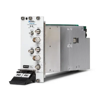
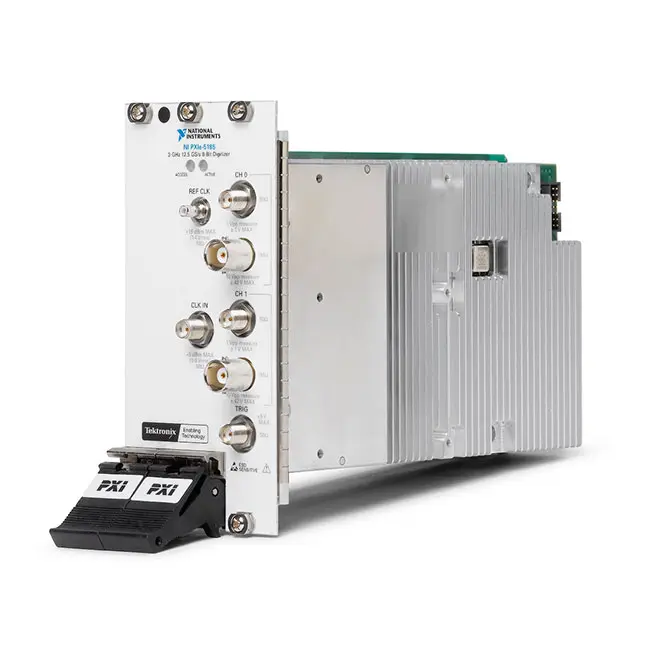
PXIe-5185 3 GHz 12.5 GS/s 8-Bit PXI Oscilloscope
Земля PXIe-5185 is a two-channel, high-speed PXI Express oscilloscope designed for automated test, broadband waveform acquisition, semiconductor validation and high-speed serial measurement applications. It combines 3 GHz analog bandwidth, 8-bit vertical resolution and a maximum real-time sampling rate of 12.5 GS/s.
The module can acquire one channel at 12.5 GS/s or two channels simultaneously at up to 6.25 GS/s per channel. Flexible input coupling, selectable input impedance, deep onboard memory, advanced triggering and PXI synchronization make it suitable for measuring fast pulses, clock signals, broadband transients and other high-frequency electronic waveforms.
Key Features of the PXIe-5185
- Two analog input channels
- 3 GHz maximum analog bandwidth
- 12.5 GS/s maximum real-time sample rate with one channel enabled
- 6.25 GS/s simultaneous sample rate per channel with two channels enabled
- 8-bit vertical resolution
- 50 Ω and 1 MΩ input support on applicable hardware versions
- AC and DC input coupling
- Programmable voltage ranges and vertical offset
- 16 MB or 512 MB onboard memory per channel
- Multirecord acquisition for rapidly occurring events
- Analog, digital, software and PXI triggering
- PXI Express high-speed data transfer
- NI-TClk synchronization with compatible PXI instruments
- Data streaming and waveform-analysis support
- NI-SCOPE instrument driver compatibility
PXIe-5185 Technical Specifications
| Product Model | PXIe-5185 |
|---|---|
| Product Type | High-speed PXI Express oscilloscope and digitizer |
| Number of Analog Channels | 2 |
| Maximum Analog Bandwidth | 3 GHz |
| Maximum Single-Channel Sample Rate | 12.5 GS/s |
| Maximum Dual-Channel Sample Rate | 6.25 GS/s per channel |
| Vertical Resolution | 8 bits |
| Input Impedance | 50 Ω and 1 MΩ on applicable versions; early versions may support 50 Ω only |
| Input Coupling | AC or DC |
| Input Range | Programmable; configuration depends on the selected impedance and hardware revision |
| Published Analog Input Voltage Span | Up to -1 V to +1 V for supported configurations |
| Onboard Memory | 16 MB or 512 MB per channel |
| Trigger Sources | Analog channels, external trigger, software and PXI trigger lines |
| Синхронизация | PXI reference clocks, PXI triggers and NI-TClk |
| Data Transfer Interface | PXI Express |
| Reconfigurable FPGA | No |
| Onboard Digital Downconverter | No |
| Peer-to-Peer Streaming | Not supported |
| Software Driver | NI-SCOPE |
| Module Format | 3U PXI Express module |
| Product Status | Discontinued with limited NI support |
PXIe-5185 Part Numbers and Memory Options
| Part Number | Onboard Memory | Описание |
|---|---|---|
| 782057-11 | 16 MB per channel | PXIe-5185, 3 GHz, 8-bit, 12.5 GS/s, two-channel oscilloscope |
| 782057-12 | 512 MB per channel | PXIe-5185 with extended acquisition memory |
Different production generations of the PXIe-5185 may have different front-panel markings, assembly numbers and supported input-impedance configurations. Confirm the complete part number, serial number, memory size and front-panel input information before ordering a replacement module.
3 GHz Analog Bandwidth
The PXIe-5185 provides up to 3 GHz of analog input bandwidth, allowing it to acquire frequency content well beyond the capabilities of general-purpose PXI oscilloscopes. It can be used to analyze broadband pulses, clock signals, high-speed data paths and intermediate-frequency signals.
Obtaining the expected bandwidth requires an appropriate signal path. Use high-quality coaxial cables, impedance-controlled fixtures, suitable connectors and correctly terminated sources. Probes, adapters and long cables can reduce bandwidth or introduce reflections.
12.5 GS/s Single-Channel Sampling
With one channel enabled, the PXIe-5185 provides real-time sampling at up to 12.5 GS/s. This corresponds to an 80 ps sampling interval and supports detailed capture of fast single-shot and nonrepetitive events.
High real-time sampling density helps characterize pulse shape, overshoot, undershoot, ringing and timing behavior. Measurement performance still depends on analog bandwidth, trigger stability, signal amplitude and the quality of the external connection.
6.25 GS/s Dual-Channel Acquisition
When both analog inputs are enabled, the PXIe-5185 can acquire two waveforms simultaneously at up to 6.25 GS/s per channel. This configuration is useful for comparing two related signals within the same acquisition.
Typical dual-channel measurements include stimulus and response, clock and data, input and output, or two nodes in a high-speed electronic circuit. Both channels share the module’s timing architecture, allowing direct timing comparison between acquired waveforms.
8-Bit Vertical Resolution
The PXIe-5185 uses an 8-bit analog-to-digital converter optimized for high-speed waveform acquisition. The architecture prioritizes bandwidth and sample rate for applications involving fast signal transitions and broadband content.
Select the smallest voltage range that safely contains the complete waveform. Proper range selection uses more of the available converter codes and improves the effective voltage resolution of the measurement.
Flexible Input Impedance
Applicable PXIe-5185 versions support both 50 Ω and 1 MΩ input impedance. The 50 Ω path is intended for impedance-controlled RF, communications and high-speed digital signal systems. The 1 MΩ path can reduce loading when measuring higher-impedance circuits.
Early PXIe-5185 hardware versions may support only 50 Ω inputs. Check the front panel and complete hardware part number before assuming that a specific module supports 1 MΩ operation.
50 Ω High-Bandwidth Measurements
The 50 Ω input path should be used when the signal source, cable and fixture are designed for a 50 Ω environment. Correct termination minimizes reflections and helps maintain the expected high-frequency response.
A source specified for a high-impedance load may produce a different amplitude when connected to a 50 Ω input. Confirm the source output specification before interpreting an apparent reduction in measured voltage.
1 MΩ Input Operation
Later dual-impedance versions of the PXIe-5185 include a 1 MΩ input path for circuits that should not be terminated with 50 Ω. This configuration supports more flexible general-purpose probing and measurement.
Bandwidth, voltage ranges, coupling behavior and overload limits can differ between the 50 Ω and 1 MΩ input paths. Review the specifications for the selected impedance before applying a signal.
AC and DC Input Coupling
DC coupling passes both the DC component and the time-varying content of a waveform. It should be selected when absolute voltage level and low-frequency behavior are part of the measurement.
AC coupling blocks much of the signal’s DC component and can help display a smaller varying waveform riding on a larger offset. The coupling mode should be selected according to the signal frequency and measurement objective.
Programmable Input Range and Offset
The PXIe-5185 provides programmable voltage ranges and vertical offset settings. These controls allow the input path to be adjusted for waveforms with different amplitudes and DC operating points.
Input ranges depend on the selected impedance and hardware revision. Ensure that the full waveform, including its offset, noise and transient peaks, remains within the configured acquisition window and absolute input limits.
Deep Onboard Acquisition Memory
The PXIe-5185 was offered with either 16 MB or 512 MB of onboard memory per channel. Deeper memory allows longer acquisition windows to be recorded while preserving a high sampling rate.
The 512 MB-per-channel version is useful for capturing long serial-data sequences, broadband transients, radar pulse trains and events that occur a significant time before or after the trigger point.
Multirecord Acquisition
Multirecord acquisition divides onboard memory into separate triggered waveform records. This enables the PXIe-5185 to acquire multiple events without transferring each record to the controller immediately after every trigger.
Reducing transfer and software overhead between events can improve test throughput. Multirecord acquisition is particularly useful for repetitive pulse measurements, production testing and intermittent fault capture.
Advanced Triggering
The PXIe-5185 supports multiple triggering modes for isolating the required portion of a waveform. Trigger sources can include an analog input channel, the external trigger connector, software commands and PXI trigger resources.
Trigger configuration can include source, level, slope, delay and reference position. Correct trigger setup is essential for stable waveform display and repeatable automated measurements.
PXI Express Data Transfer
The PXI Express interface provides high-throughput communication between the PXIe-5185 and the system controller. Acquired waveform data can be transferred to host memory for storage, visualization and custom processing.
Sustained transfer performance depends on the PXI Express chassis, controller, slot bandwidth, system architecture, record size and software configuration. The PXIe-5185 does not provide NI peer-to-peer streaming support.
PXI Synchronization and NI-TClk
PXI reference clocks, trigger lines and NI-TClk technology allow the PXIe-5185 to be synchronized with compatible oscilloscopes, waveform generators and other modular instruments.
Multiple digitizers can be combined when an application requires more than two synchronized channels. A signal generator can also produce a stimulus aligned with the PXIe-5185 acquisition for automated response testing.
NI-SCOPE Software Support
The PXIe-5185 is controlled through the NI-SCOPE instrument driver. NI-SCOPE provides functions for configuring input channels, voltage ranges, coupling, sample rates, record lengths, triggers and waveform transfers.
The driver supports automated development with LabVIEW, LabWindows/CVI, C, C++ and compatible .NET environments. NI software also provides data-streaming and waveform-analysis functions for building automated measurement systems.
InstrumentStudio Integration
Compatible NI software can provide an interactive soft front panel for configuring the PXIe-5185, viewing waveforms and validating connections before developing an automated test program.
Interactive testing is useful when verifying signal amplitude, impedance, coupling and trigger behavior. Once the configuration is confirmed, the settings can be reproduced in an NI-SCOPE application or automated test sequence.
Typical PXIe-5185 Applications
- High-speed automated test equipment
- Broadband waveform acquisition
- High-speed serial signal characterization
- Clock and data analysis
- Fast pulse and transient capture
- Валидация полупроводников
- Communications-system testing
- Radar and pulsed RF measurement
- Time-domain component characterization
- Production functional testing
- Multichannel synchronized measurement
- Research and laboratory automation
High-Speed Serial Signal Testing
The 3 GHz bandwidth and 12.5 GS/s sampling rate make the PXIe-5185 suitable for characterizing high-speed clocks and serial data waveforms. Acquired data can be used to evaluate amplitude, timing, overshoot, undershoot, ringing and signal-integrity behavior.
The maximum serial-data rate that can be evaluated depends on the required harmonics, measurement method, signal standard and analysis software. The complete fixture response must be considered when interpreting the results.
Fast Pulse and Transient Capture
The PXIe-5185 can capture fast, nonrepetitive pulses using real-time sampling. Deep memory supports longer observation periods, while multirecord acquisition can store a series of triggered transient events.
Applications include component switching analysis, fault-event capture, pulsed laser measurements, radar pulse characterization and fast detector readout.
Валидация полупроводников
The module can be combined with PXI waveform generators, digital instruments, source measure units and switches to create an automated semiconductor validation platform. It can measure the high-speed output behavior of clock devices, amplifiers, converters and communication interfaces.
When characterizing devices near 3 GHz, account for cable loss, connector response, fixture insertion loss and impedance discontinuities. Fixture compensation may be required for accurate device-level conclusions.
Communications and IF Testing
The PXIe-5185 can acquire broadband intermediate-frequency signals for time-domain and software-based frequency-domain analysis. Captured waveforms can be transferred to the controller for demodulation, spectral processing or custom measurements.
Because the module has 8-bit resolution, confirm that its dynamic range is suitable when measuring small signals near substantially larger carriers or interferers.
Production Test Systems
The PXIe-5185 can operate as part of a compact PXI Express production test platform. Software-controlled configuration, triggering and waveform transfer support repeatable measurements without manual oscilloscope adjustment.
For discontinued equipment, maintaining a validated spare module can reduce production downtime. Replacement units should be checked for part number, memory configuration, supported input impedance and calibration status.
PXIe-5185 Troubleshooting
The PXIe-5185 Is Not Detected in NI MAX
Confirm that the module is fully installed in a compatible PXI Express or hybrid-compatible slot. Check chassis power, controller communication and the installed NI-SCOPE version, then rescan the system in NI Measurement & Automation Explorer.
The Module Does Not Support the Expected 1 MΩ Input
Some early PXIe-5185 versions support only 50 Ω input operation. Check the front-panel markings and complete module part number to identify the supported impedance configuration.
The Measured Amplitude Is Lower Than Expected
Verify whether the channel is configured for 50 Ω or 1 MΩ input impedance. A high-impedance source can show a significant amplitude change when connected to a 50 Ω load.
The Waveform Is Clipped
Select a larger input range or adjust the vertical offset. Make sure the waveform’s amplitude, DC level and transient peaks remain inside the acquisition range and the applicable maximum-input specification.
The Signal Shows Excessive Ringing
Inspect cables, adapters, connector transitions and fixture traces for impedance discontinuities. Use suitable high-frequency coaxial cables and terminate 50 Ω signal paths correctly.
The 12.5 GS/s Rate Is Unavailable
The maximum 12.5 GS/s real-time sampling rate applies when one channel is enabled. With both channels enabled, the maximum simultaneous rate is 6.25 GS/s per channel.
Triggered Events Are Being Missed
Review the trigger source, level, slope and delay. Use multirecord acquisition when events occur too rapidly for a complete waveform transfer after each trigger.
Long Records Transfer Slowly
Review the record length, number of records, controller performance and PXI Express slot bandwidth. Transfer only the waveform data required by the application and process records in blocks where possible.
Two Modules Are Not Properly Synchronized
Confirm that all participating modules share the intended PXI reference clock and trigger resources. Configure compatible instruments through NI-TClk and verify that the chassis supports the required timing architecture.
The Measurement Changes After the System Warms Up
Allow the chassis and module to reach a stable operating temperature, maintain adequate cooling and perform the recommended self-calibration procedure before critical measurements.
PXIe-5185 Comparison with Similar PXI Oscilloscopes
| Модель | Key Configuration | Best Suited For |
|---|---|---|
| PXI-5154 | 1 GHz, 8-bit, up to 2 GS/s | Maintaining legacy PXI systems with moderate high-frequency requirements |
| PXIe-5160 | 500 MHz, 10-bit, 2.5 GS/s | Applications requiring greater vertical resolution at lower bandwidth |
| PXIe-5162 | Up to 1.5 GHz, 10-bit, 5 GS/s | Balanced bandwidth, sampling speed and vertical resolution |
| PXIe-5185 | 3 GHz, 8-bit, 12.5 GS/s, two channels | Very-high-speed broadband and transient acquisition |
| PXIe-5186 | 5 GHz, 8-bit, 12.5 GS/s, two channels | Applications requiring bandwidth beyond 3 GHz |
PXIe-5185 vs PXIe-5186
The PXIe-5185 provides 3 GHz analog bandwidth, while the PXIe-5186 increases the maximum bandwidth to 5 GHz. Both models provide two 8-bit channels and sampling rates up to 12.5 GS/s with one channel enabled.
Choose the PXIe-5185 when 3 GHz bandwidth is sufficient for the signal and application. Select the PXIe-5186 when additional analog bandwidth is required for faster edges, higher-frequency carriers or wider-bandwidth pulses.
PXIe-5185 vs PXIe-5162
The PXIe-5185 offers higher analog bandwidth and sampling speed than the PXIe-5162. The PXIe-5162 provides 10-bit resolution, making it more suitable when vertical fidelity and dynamic range are more important than the highest acquisition bandwidth.
Select the PXIe-5185 for very fast broadband waveforms. Choose the PXIe-5162 when the application benefits from higher resolution and its lower bandwidth remains sufficient.
PXIe-5185 vs PXI-5154
The PXIe-5185 provides 3 GHz bandwidth and sampling up to 12.5 GS/s, substantially exceeding the 1 GHz bandwidth and 2 GS/s maximum rate of the PXI-5154.
The PXI-5154 is appropriate for legacy PXI chassis and lower-performance measurements. The PXIe-5185 requires a compatible PXI Express chassis and is intended for significantly faster signals.
Recommended Related Products
- PXIe-5186 5 GHz 12.5 GS/s PXI Oscilloscope
- PXIe-5162 10-Bit PXI Express Oscilloscope
- PXIe-5160 500 MHz PXI Express Oscilloscope
- PXI-5154 1 GHz PXI Oscilloscope
- PXIe-5442 Arbitrary Waveform Generator
- View More NI PXI and PXI Express Modules
Selecting the Right PXI Oscilloscope
Choose the PXIe-5185 when the application requires two channels, up to 3 GHz analog bandwidth and real-time sampling up to 12.5 GS/s. It is particularly useful for fast pulse capture, high-speed digital measurements and maintaining existing automated systems designed around this model.
Select the PXIe-5186 when bandwidth beyond 3 GHz is required. Consider the PXIe-5160 or PXIe-5162 when higher vertical resolution is more important than maximum bandwidth and sample rate.
Purchasing a Discontinued PXIe-5185
NI lists the PXIe-5185 as discontinued with limited support. Availability may therefore consist of unused surplus, previously installed or refurbished modules rather than newly manufactured inventory.
Before purchasing, verify the part number, memory configuration, input-impedance version, serial number, calibration status and operating condition. The module should be tested for channel acquisition, input configuration, triggering, synchronization and communication with NI-SCOPE.
Why Choose the PXIe-5185?
- Provides 3 GHz analog bandwidth
- Samples one channel at up to 12.5 GS/s
- Samples two channels simultaneously at up to 6.25 GS/s each
- Supports high-speed single-shot waveform capture
- Offers up to 512 MB acquisition memory per channel
- Provides flexible input configuration on applicable versions
- Supports multirecord acquisition and advanced triggering
- Integrates with PXI timing and NI-TClk synchronization
- Supports automated operation through NI-SCOPE
Frequently Asked Questions
What Is the PXIe-5185?
The PXIe-5185 is a two-channel, 3 GHz, 8-bit PXI Express oscilloscope designed for high-speed waveform acquisition and automated testing.
What Is the Maximum Sample Rate?
The maximum real-time sample rate is 12.5 GS/s with one channel enabled. When both channels are enabled, the maximum rate is 6.25 GS/s per channel.
What Is the Analog Bandwidth?
The PXIe-5185 provides up to 3 GHz of analog input bandwidth.
How Many Input Channels Does It Provide?
The module provides two analog input channels.
What Is the Vertical Resolution?
The PXIe-5185 uses an 8-bit analog-to-digital converter.
Does Every PXIe-5185 Support 1 MΩ Inputs?
No. Applicable later hardware versions support 50 Ω and 1 MΩ input impedance, while some early PXIe-5185 modules support only 50 Ω. Verify the front panel and complete part number.
How Much Onboard Memory Is Available?
The standard version provides 16 MB per channel, while the extended-memory version provides 512 MB per channel.
What Is the Difference Between 782057-11 and 782057-12?
Part number 782057-11 provides 16 MB of onboard memory per channel. Part number 782057-12 provides 512 MB per channel.
Can Multiple PXIe-5185 Modules Be Synchronized?
Yes. Compatible modules can be synchronized using PXI timing resources and NI-TClk, subject to the chassis and complete system configuration.
Which Software Controls the PXIe-5185?
The module is controlled with the NI-SCOPE instrument driver and can be integrated with LabVIEW and supported text-based programming environments.
Is the PXIe-5185 Still Manufactured?
No. NI lists the PXIe-5185 as no longer available for purchase and under limited support. Replacement inventory may be available through surplus and used-equipment suppliers.
Request a Quote for the PXIe-5185
Contact us for current availability, condition, calibration information and project pricing for the PXIe-5185 3 GHz 12.5 GS/s PXI Oscilloscope. We can also help verify the memory configuration, input-impedance version, compatible PXI Express chassis and suitable replacement models for your test system.















