






Показаны все (2)

Фильтр по цене
Фильтровать по брендам

- Национальные инструменты
- PCI ModulesPCI Modules
- Системы PXI
- PXI Шасси
- PXI Контроллер
- Модули PXI
- PXI Semiconductor Test
- PXI FPGA and RIO Modules
- PXI MXI Interfaces
- PXI Programmable Power Supplies & SMU
- PXI Sensor Measurements
- Генераторы сигналов PXI
- PXI Vision
- Сбор данных PXI
- Осциллографы/Цифровые преобразователи PXI
- PXI Счетчики/Таймеры
- PXI РЧ и беспроводное тестирование
- PXI GPIB, Ethernet and VXI
- PXI-коммутаторы
- Цифровые мультиметры PXI
- Цифровой ввод-вывод PXI
- Промышленная связь PXI
- Динамический анализ сигналов PXI
- Передача данных PXI
- CompactDAQ Systems
- CompactRIO Systems
- PCI Modules
- USB Devices
- Устройство программно-определяемого радио USRP
- ключи
- ТекТроникс
NI PXI Semiconductor Test Instruments
NI PXI Semiconductor Test instruments provide ATE-class digital pattern generation, response comparison, per-pin parametric measurement and multisite execution within a modular PXI Express platform. They are designed for semiconductor characterization, validation and production testing of digital and mixed-signal integrated circuits.
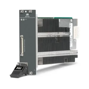
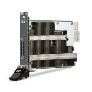
The PXI Semiconductor Test category currently includes the PXIe-6570 and PXIe-6571 Digital Pattern Instruments. These modules combine programmable digital pin electronics, vector-based pattern execution, hardware comparison, source and capture resources, frequency measurement and per-pin parametric measurement capabilities.
What Is a PXI Digital Pattern Instrument?
A PXI Digital Pattern Instrument applies programmed logic states to a semiconductor device and compares the DUT response with expected values at defined timing points. Unlike basic static digital I/O, it provides per-pin voltage levels, precise edge placement, vector sequencing, hardware pass/fail comparison and debugging resources designed specifically for semiconductor testing.
Each digital channel can be assigned to a logical DUT pin through a pin map. Engineers can then define voltage levels, timing sets, pattern files, specifications and test flows without rewriting the hardware interface for every test.
Typical digital semiconductor tests include:
- Functional verification of digital interfaces
- Digital communication protocol testing
- Input and output voltage characterization
- Timing and frequency characterization
- Continuity, leakage and parametric measurements
- Scan-pattern execution and design-for-test validation
- Multisite production testing
- Mixed-signal IC digital subsystem testing
PXI Semiconductor Test System Functions
| Test Function | Typical PXI Instrument | Purpose | Selection Factors |
|---|---|---|---|
| Digital Functional Test | Digital Pattern Instrument | Drives digital patterns and compares DUT responses in hardware | Channel count, vector rate, timing accuracy, voltage range and pattern memory |
| Per-Pin Parametric Test | Integrated PPMU | Forces or measures voltage and current on individual digital pins | Force range, measurement range, accuracy, compliance and bank architecture |
| Precision DC Characterization | Source Measure Unit | Measures device leakage, I-V characteristics and power-rail behavior | Voltage, current, sensitivity, channel density, pulse capability and settling time |
| RF and Mixed-Signal Test | VST, signal generator, analyzer or digitizer | Generates and analyzes RF or analog signals | Frequency, bandwidth, dynamic range, synchronization and calibration plane |
| Signal Routing | PXI Switch Module | Connects shared instruments to multiple DUT pins or test sites | Topology, voltage, current, bandwidth, leakage and switching life |
| System Synchronization | PXI Timing Module | Distributes clocks and triggers across instruments or digital subsystems | Clock accuracy, trigger routing, skew and multichassis requirements |
This category contains the dedicated PXIe-6570 and PXIe-6571 Digital Pattern Instruments. SMUs, RF instruments, switches and DMMs used to complete a semiconductor test system remain in their respective PXI product categories to avoid assigning the same model to multiple categories.
PXIe-6570 and PXIe-6571 Comparison
| Модель | Unique Category | Core Architecture | Best Fit |
|---|---|---|---|
| PXIe-6570 | Two-Slot Digital Pattern Instrument | 32 bidirectional digital channels, two-slot PXIe form factor, 100 MVector/s maximum vector rate, 128M-vector memory per channel and up to 256 channels in one digital subsystem | Existing PXIe-6570 test programs, established semiconductor platforms and 32-channel digital functional test |
| PXIe-6571 | High-Density Digital Pattern Instrument | 8- or 32-channel variants, one-slot PXIe form factor, 100 MVector/s maximum vector rate, 128M-vector memory per channel and up to 512 channels with 32-channel modules | High-density digital subsystems, multisite testing and new semiconductor characterization or production platforms |
Both instruments support semiconductor functional, timing, voltage and parametric testing. Their common 100 MHz maximum vector rate does not make them interchangeable: physical width, channel variants, subsystem scalability, cooling requirements, supported revisions and synchronization architecture must also be considered.
How to Select a PXI Semiconductor Test Instrument
1. Calculate the Required Digital Channel Count
Count every DUT pin that must be driven, compared or measured during the test. Include control pins, communication interfaces, clocks, scan pins, resets, interrupts and spare channels required for future device revisions.
The PXIe-6570 provides 32 digital channels and occupies two PXIe slots. The PXIe-6571 is available in 8-channel and 32-channel configurations and occupies one slot. The PXIe-6571 therefore offers greater channel density when building large digital subsystems.
For multisite testing, calculate the channels required per DUT and multiply by the maximum number of sites that will run in parallel. Do not use only the package pin count because power, ground, analog and unused pins may not require digital pattern channels.
2. Define Logic Voltage and Parametric Requirements
Confirm the DUT logic families, nominal supply voltage, input thresholds, output levels and allowable pin voltage. Both instrument families provide programmable digital levels and per-pin parametric measurement resources, but the test limits must remain within the supported voltage and current ranges.
Determine whether the test requires:
- Programmable drive-high and drive-low levels
- Programmable compare-high and compare-low thresholds
- Active-load or termination behavior
- Force-voltage and measure-current operation
- Force-current and measure-voltage operation
- Continuity, leakage or open/short testing
- DUT Ground Sense for improved accuracy at higher currents
The integrated PPMU is useful for pin-level measurements, but it is not a replacement for a precision SMU when the application requires lower-current sensitivity, higher source power, four-quadrant operation or specialized pulsing.
3. Determine the Required Vector Rate
Vector rate defines how quickly the instrument executes pattern vectors. Both PXIe-6570 and PXIe-6571 support maximum vector rates of 100 MVector/s, corresponding to a minimum standard vector period of 10 ns.
The effective digital data rate can also depend on edge-multiplier mode, pattern format, pulse-width requirements and the selected timing edges. Maximum vector rate should not be treated as a guarantee that every voltage, edge or pattern configuration can operate at the maximum speed.
For protocol testing, calculate timing from the complete transaction rather than selecting an instrument only from the interface clock frequency. Setup time, hold time, edge placement, turnaround cycles and response latency can all affect the required pattern configuration.
4. Evaluate Timing Accuracy and Edge Placement
Digital semiconductor characterization often requires sweeping an input edge or compare strobe relative to a DUT response. These measurements are used to determine setup time, hold time, propagation delay and timing margin.
Review vector-period resolution, edge-placement resolution, drive and compare accuracy and timing repeatability. The required instrument timing accuracy should be small enough relative to the DUT specification and production guard band.
Timing resolution and timing accuracy are different specifications. A very small programmable timing step does not mean the actual edge has the same absolute accuracy.
5. Plan Multisite Test Architecture
Multisite testing applies the same test flow to several DUTs in parallel. It can improve production throughput, but the complete system must have sufficient digital channels, source and capture resources, DC channels, RF paths, switching and fixture connections for every site.
Both PXIe-6570 and PXIe-6571 provide resources for up to eight test sites per digital pattern instrument. The practical site count depends on the number of digital pins required by each DUT and whether resources can be shared safely between sites.
When evaluating multisite efficiency, consider:
- Number of DUT pins per site
- Shared and site-specific power rails
- Pattern branching and per-site pass/fail behavior
- PPMU bank organization
- Source, capture and history RAM resources
- Fixture and device interface board layout
- Handler or prober communication
- Test time added by serial operations
6. Review Pattern and History Memory
Digital pattern instruments store compiled vectors in onboard memory. Both product families provide 128M vectors of large vector memory per channel. Actual pattern capacity depends on the compiled pattern structure, opcodes, source and capture data and scan-pattern implementation.
History RAM records information around failures to support debugging. When testing multiple sites, history resources may be divided among the active sites, reducing the number of retained cycles per site.
Large scan-test patterns should be evaluated before the system is finalized. Supported scan opcodes can reduce the vector-memory requirement for long serial scan operations, but compression depends on the number and arrangement of scan input and output pins.
7. Confirm Synchronization Requirements
Multiple Digital Pattern Instruments can be synchronized to create a larger digital subsystem. This may require compatible module types, matching channel configurations, suitable chassis slots and a supported timing module.
PXIe-6570 and PXIe-6571 should not be assumed to form one synchronized digital subsystem together. NI synchronization configurations require compatible instruments, and PXIe-6571 modules used in a group must have matching channel counts.
For systems combining digital pattern, SMU, RF and analog instruments, define whether the instruments only need a common start trigger or require phase-related clocks and precisely aligned events.
8. Check Chassis Power and Cooling
The PXIe-6571 has high power and cooling requirements despite its one-slot form factor. The 8-channel version requires a chassis with at least 58 W slot cooling, while the 32-channel version requires 82 W slot cooling under its specified operating conditions.
This requirement can limit the compatible chassis models. A suitable configuration may use the PXIe-1092 for a compact high-power system or the PXIe-1095 when more instrument capacity is required.
For the PXIe-6570, verify the selected chassis, fan setting, available adjacent slot and total system power. The chassis fan must be configured according to the instrument specifications.
9. Design the DUT Interface
The digital pattern module is only one part of the signal path. Semiconductor testing normally requires compatible cables and a device interface board that connects instrument channels to the DUT socket, probe card or production handler interface.
Interface design should address:
- Pin mapping and connector compatibility
- Controlled impedance and return paths
- Trace length and channel-to-channel skew
- Grounding and DUT Ground Sense
- Protection against overvoltage and electrostatic discharge
- Relay and switching parasitics
- Socket, probe and fixture contact resistance
- Calibration and maintenance access
A poor device interface board can reduce signal integrity and measurement accuracy even when the digital instrument meets the required specification.
PXIe-6570 or PXIe-6571?
| Selection Requirement | PXIe-6570 Direction | PXIe-6571 Direction |
|---|---|---|
| Existing Validated Test Program | Appropriate when the existing platform was developed and qualified with PXIe-6570 | Migration requires checking fixtures, synchronization, software and requalification |
| Slots per 32 Channels | Two PXIe slots | One PXIe slot |
| Available Channel Variants | 32 channels | 8 or 32 channels |
| Maximum Digital Subsystem Size | Up to 256 channels | Up to 512 channels with 32-channel modules |
| New High-Density Platform | Lower channel density | Preferred when one-slot density and larger channel scalability are required |
| Chassis Cooling | Verify chassis compatibility and required fan configuration | At least 58 W for 8-channel or 82 W for 32-channel operation |
Do not select the PXIe-6571 only because it occupies fewer slots. Its high per-slot cooling requirement must be checked against the exact chassis model. A physically open PXIe slot may not provide sufficient power and cooling.
Building a Complete PXI Semiconductor Test System
Digital Functional Test
The PXIe-6570 or PXIe-6571 executes digital patterns, applies programmed voltage levels, compares DUT responses and performs per-pin measurements. This forms the digital subsystem of the test platform.
Power and DC Parametric Measurement
PXI power supplies and SMUs provide DUT power, supply-current measurement, I-V sweeps, leakage testing and precision DC characterization. Select them according to voltage, current, sensitivity, pulsing and channel-density requirements.
Signal Routing
PXI switch modules can route shared instruments between DUT pins or test sites. Switching must be evaluated for leakage, contact resistance, bandwidth, voltage, current and settling time.
RF and Mixed-Signal Testing
RF front ends, transceivers, wireless ICs and mixed-signal devices may require PXI RF and wireless instruments, oscilloscopes, digitizers or signal generators in addition to digital pattern hardware.
Precision Measurements
Цифровые мультиметры PXI can provide additional voltage, resistance and current measurements when the required function or accuracy is outside the integrated PPMU capability.
Software for PXI Semiconductor Test
The PXIe-6570 and PXIe-6571 use the NI-Digital Pattern Driver. Digital Pattern Editor provides an interactive environment for creating and debugging pin maps, specifications, levels, timing sets, patterns and test configurations.
Common software functions include:
- Pin and channel mapping
- Digital level and timing configuration
- Pattern compilation and execution
- Shmoo plotting for voltage and timing characterization
- Digital scope and pin-state debugging
- History RAM failure analysis
- Source and capture waveform configuration
- Per-site result and pass/fail handling
Automated applications can use supported LabVIEW, C or .NET APIs. TestStand can coordinate digital pattern execution with SMUs, RF instruments, switching, handlers and reporting as part of a production test sequence.
Before purchasing hardware for an existing system, confirm the required NI-Digital Pattern Driver version, Digital Pattern Editor version, operating system and application-development environment.
Typical Semiconductor Applications
- Digital and mixed-signal IC characterization
- Power management IC validation
- RF front-end and wireless IC testing
- Microcontroller and system-on-chip functional test
- Sensor and interface IC validation
- Digital communication protocol testing
- Memory and scan-pattern execution
- Wafer-level engineering characterization
- Multisite packaged-device production test
- Device qualification and regression testing
Legacy System Replacement
Replacing a PXIe-6570 with a PXIe-6571 is not automatically a drop-in hardware change. Although both families support similar digital pattern concepts, they differ in slot width, channel configurations, subsystem scalability, power and cooling requirements and supported synchronization groupings.
Review the following before migrating:
- Existing pin maps, levels, timing sets and pattern files
- NI-Digital Pattern Driver and software versions
- Digital Pattern Editor project compatibility
- Cable and device interface board connections
- Chassis slot power and cooling capability
- Synchronization and timing-module requirements
- Custom APIs and production test sequences
- Calibration and correlation requirements
- Production guard bands and system requalification
For validated production equipment, sourcing the original model may involve less engineering risk than changing the digital subsystem without a complete correlation study.
PXI Semiconductor Test Procurement and RFQ Guide
Provide the following information for product selection and quotation:
- Required module model and complete part number
- Required quantity and product condition
- DUT type and number of digital pins
- Required logic voltage range
- Required vector rate and timing accuracy
- Pattern-memory or scan-test requirements
- Number of parallel test sites
- Existing PXIe chassis and controller models
- Timing and synchronization hardware
- Required cables, connector blocks or interface-board information
- NI-Digital Pattern Driver and software version
- Calibration requirements
- Required delivery date and destination
For pre-owned instruments, request chassis recognition, self-test results, digital channel functional testing, connector inspection and calibration information. Detection in NI MAX alone does not verify digital-level accuracy, timing performance or PPMU operation.
Часто задаваемые вопросы
What is the main difference between PXIe-6570 and PXIe-6571?
The PXIe-6570 provides 32 channels in a two-slot module and supports digital subsystems of up to 256 channels. The PXIe-6571 provides 8- or 32-channel versions in a one-slot module and supports up to 512 channels when using 32-channel modules.
Can PXIe-6570 and PXIe-6571 be synchronized as one digital subsystem?
No. They should not be grouped as one synchronized digital subsystem. Multiple PXIe-6571 instruments used in a synchronized group must also have matching channel-count configurations.
Can a digital pattern instrument replace an SMU?
Not completely. The integrated PPMU supports useful per-pin voltage and current measurements, but a dedicated SMU is required when the test needs greater sensitivity, higher power, wider operating ranges, four-quadrant operation or specialized pulse capability.
What chassis is required for PXIe-6571?
The PXIe-6571 8-channel version requires at least 58 W of cooling capacity in its slot, while the 32-channel version requires an 82 W slot. Confirm the exact chassis specification before ordering.
What is a vector in semiconductor digital testing?
A vector defines the drive, compare or high-impedance state applied to each digital pin during one pattern period. A test pattern consists of sequences of vectors combined with timing sets, levels and execution-control instructions.
What is multisite semiconductor testing?
Multisite testing runs the same test flow on several DUTs in parallel. It can reduce average test time per device but requires sufficient digital channels, DC resources, switching, interface-board connections and per-site result handling.
What additional hardware is needed with a Digital Pattern Instrument?
A complete system normally requires a compatible PXIe chassis, controller, software, cable and DUT interface board. Depending on the device, it may also require SMUs, programmable power supplies, RF instruments, digitizers, switches and timing hardware.
Recommended PXI Semiconductor Test Instruments
Choose the PXIe-6570 when maintaining an established 32-channel test platform or matching an existing validated configuration. Select the PXIe-6571 when a new system requires one-slot channel density, 8- or 32-channel options or a larger synchronized digital subsystem.
Related NI PXI Solutions
Build a complete semiconductor test platform with a compatible Шасси PXI, PXI controller, precision power instruments, switching, RF hardware and other PXI модули selected for the DUT and test-flow requirements.
NI PXI Semiconductor Test Instruments from PXISOURCE
PXISOURCE supports semiconductor laboratories, system integrators and production-test teams with digital pattern instrument sourcing, PXIe chassis compatibility review, module selection, accessory matching and legacy-system replacement. Send the DUT pin count, voltage levels, vector rate, test-site quantity, chassis model and required product condition for a technically matched quotation.
Need help selecting an NI PXI semiconductor test instrument? Email sales@pxisource.com or contact PXISOURCE through WhatsApp.