




Показаны все (2)

Фильтр по цене
Фильтровать по брендам

- Национальные инструменты
- Системы PXI
- PXI Шасси
- PXI Контроллер
- Модули PXI
- PXI Semiconductor Test
- PXI FPGA and RIO Modules
- PXI MXI Interfaces
- PXI Programmable Power Supplies & SMU
- PXI Sensor Measurements
- Генераторы сигналов PXI
- PXI Vision
- Сбор данных PXI
- Осциллографы/Цифровые преобразователи PXI
- PXI Счетчики/Таймеры
- PXI РЧ и беспроводное тестирование
- PXI GPIB, Ethernet and VXI
- PXI-коммутаторы
- Цифровые мультиметры PXI
- Цифровой ввод-вывод PXI
- Промышленная связь PXI
- Динамический анализ сигналов PXI
- Передача данных PXI
- CompactDAQ Systems
- CompactRIO Systems
- PCI Modules
- USB Devices
- Устройство программно-определяемого радио USRP
- Системы PXI
- ключи
- ТекТроникс

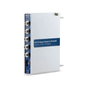
NI C Series FPGA Adapter Modules
NI C Series FPGA adapter modules provide an interface path between CompactRIO FPGA hardware, C Series I/O architecture and application-specific external signals or accessories. They are used when standard analog, digital or communication modules do not provide the required signal routing, timing behavior, connector arrangement or custom I/O implementation.
These modules are intended for engineers building deterministic embedded systems, specialized test fixtures, custom signal interfaces and FPGA-based control applications. Selection must consider the CompactRIO chassis and controller, FPGA resources, electrical interface, pin mapping, signal conditioning, timing requirements and LabVIEW FPGA development environment.
What Is a C Series FPGA Adapter Module?
A C Series FPGA adapter module is an interface component used to connect external circuits, custom electronics or specialized I/O arrangements to a CompactRIO FPGA-based system. It can provide a practical bridge between the C Series module format and the application-specific wiring, connector or conditioning requirements of the final system.
Unlike a conventional C Series analog input, temperature, counter or communication module, an FPGA adapter module may not independently provide measurement conversion, sensor excitation, electrical isolation or protocol processing. Its exact capability depends on the specific module and associated accessory or external circuit.
An FPGA adapter module should not be treated as a universal signal conditioner. Confirm the exact voltage limits, I/O direction, protection, isolation, power requirements and connector pinout before connecting field wiring or external electronics.
When to Use an FPGA Adapter Module
| Requirement | Why an FPGA Adapter Module May Fit | Key Verification Point |
|---|---|---|
| Custom digital interface | Supports application-specific digital routing and FPGA-controlled signal handling | Logic levels, I/O direction, timing and protection requirements |
| Specialized connector or fixture interface | Provides an adaptable connection path between external equipment and CompactRIO I/O | Pinout, cable assembly, grounding and mechanical compatibility |
| Deterministic FPGA processing | Allows custom triggering, filtering, state-machine logic or digital protocol handling | FPGA resources, loop timing and software-development requirements |
| Custom signal conditioning | Can be combined with external conditioning designed for the required signal | Voltage range, isolation, sensor excitation and safety limits |
| Legacy-system integration | Helps connect specialized or nonstandard field wiring to a modern CompactRIO system | Electrical compatibility and required interface conversion |
| Prototype or research system | Supports flexible hardware development before a dedicated interface is finalized | Validation, test coverage and production-readiness requirements |
FPGA Adapter Modules Compared with Standard C Series I/O
| Функция | Standard C Series I/O Module | C Series FPGA Adapter Module |
|---|---|---|
| Primary Purpose | Predefined measurement, control or communication function | Application-specific interface and FPGA-oriented I/O integration |
| Signal Conditioning | Often integrated for the supported input or output type | May require external conditioning or custom interface circuitry |
| Конфигурация | Typically configured with supported driver functions | Often requires explicit FPGA and hardware-interface design |
| Timing Behavior | Defined by the module architecture and driver support | Can support application-specific FPGA timing and logic |
| Best Fit | Established sensor, actuator and communication requirements | Custom electronics, specialized fixtures and deterministic embedded designs |
How to Select a C Series FPGA Adapter Module
1. Confirm CompactRIO Platform Compatibility
Start with the existing or planned CompactRIO chassis and controller. Verify that the adapter module is compatible with the C Series slot, chassis generation, FPGA architecture, operating mode and required software version.
Not every C Series module supports every CompactRIO platform or programming method. Compatibility should be confirmed using the exact part number, not only the module family name.
2. Define the External Electrical Interface
Document every connected signal: voltage range, current level, logic family, source impedance, I/O direction, common reference, cable length and expected fault conditions. The FPGA adapter and connected circuitry must safely support the complete interface.
External signal conditioning may be needed for analog voltage, current loops, thermocouples, RTDs, bridge sensors, high-voltage signals, relay loads or industrial field wiring. Do not connect these signals directly unless the adapter documentation explicitly permits it.
3. Verify Pin Mapping and Connector Requirements
Custom FPGA interfaces depend on correct signal-to-pin mapping. Review connector type, cable orientation, channel allocation, ground returns, shield connections and any required breakout board or terminal assembly.
Maintain controlled documentation for the final wiring diagram. A pinout error can cause failed measurements, incorrect control behavior or damage to the adapter, connected equipment or external interface board.
4. Determine Required Timing and Determinism
Define whether the application needs standard software-timed acquisition, deterministic real-time control, precise digital triggering, high-speed protocol handling or custom FPGA loop timing. The timing requirement determines whether FPGA implementation is necessary and how the I/O should be processed.
For closed-loop control, machine protection or event response, calculate the complete response path: input detection, FPGA logic, output update, external device response and any required safety interlock.
5. Review Isolation, Protection and Power
Determine whether the field interface requires galvanic isolation, overvoltage protection, current limiting, transient suppression or external power distribution. These functions may be provided by the external interface design rather than by the adapter module.
Industrial installations, long cable runs, motors, solenoids, relays and powered sensors should be reviewed for electrical noise, grounding and fault-energy exposure before the system is deployed.
6. Plan for FPGA Resource Use
Custom I/O processing consumes FPGA resources. Account for logic, memory, timing loops, DMA transfers, protocol handling, filtering and any data buffering required by the application. A design that compiles for a small prototype may need additional planning when channel count or processing complexity increases.
LabVIEW FPGA and Software Considerations
C Series FPGA adapter modules are commonly used in applications developed with LabVIEW FPGA and CompactRIO software tools. FPGA programming can provide deterministic hardware-level processing for custom logic, triggering, pulse handling, data reduction and control decisions.
Depending on the module and system design, the application may use LabVIEW Real-Time, the Scan Engine, LabVIEW FPGA or a combination of these environments. Confirm the required driver, development environment and deployment target before selecting hardware.
Use DMA transfers and appropriately sized buffers when moving data from FPGA logic to the real-time controller or host application. The software architecture should separate deterministic FPGA processing from slower logging, display, network communication and file-writing tasks.
Signal Integrity and System Integration
Cabling and Shielding
Use cable types appropriate for the signal frequency, voltage, environment and grounding scheme. Route low-level, high-speed or differential signals away from noisy power wiring, motors, contactors and switching loads where practical.
Custom Interface Validation
Validate custom interfaces with representative signals and fault conditions before installation. Testing should include normal operation, startup behavior, cable disconnection, power sequencing, noise exposure and any expected overload or error state.
System Documentation
Maintain the module part number, connector pinout, external schematic, signal ranges, power sources, grounding arrangement, FPGA version and software version together. This documentation is important for maintenance, troubleshooting and future system replication.
Типичные применения
- Custom CompactRIO test fixtures and interface panels
- FPGA-based machine control and deterministic automation
- Specialized digital protocols and custom timing logic
- Hardware-in-the-loop simulation and validation systems
- Research platforms requiring custom external electronics
- Legacy-interface migration to CompactRIO hardware
- Motion, robotics and position-control systems
- Industrial monitoring with application-specific signal conditioning
- Automotive, aerospace and energy test applications
- Prototype systems progressing toward production hardware
C Series FPGA Adapter Module Procurement Guide
Provide the following information for accurate module selection and technical review:
- Existing or planned CompactRIO chassis and controller model
- Required FPGA, real-time or Scan Engine application architecture
- External device, fixture or custom-circuit documentation
- Complete signal list with voltage, current, logic level and I/O direction
- Required channel count, pin mapping and connector type
- Required timing, trigger, latency and synchronization behavior
- Isolation, protection, grounding and cable-length requirements
- External power, sensor excitation and signal-conditioning requirements
- Required breakout boards, terminal blocks, cables and enclosure integration
- LabVIEW, NI driver and operating-system version
- Required quantity, preferred product condition and delivery destination
Часто задаваемые вопросы
Does an FPGA adapter module replace a standard analog or digital I/O module?
Not necessarily. Standard C Series I/O modules provide defined measurement or control functions. An FPGA adapter module is intended for specialized interfaces and may require external conditioning or custom electronics.
Do I need LabVIEW FPGA to use a C Series FPGA adapter module?
Many custom FPGA-interface applications require LabVIEW FPGA development. The exact software requirement depends on the specific module, CompactRIO platform and intended operating mode.
Can I connect industrial 24 V signals directly to an adapter module?
Only if the exact module documentation explicitly supports the required voltage and wiring arrangement. Otherwise, use suitable external signal conditioning, protection and isolation.
Can FPGA adapter modules be used in CompactDAQ chassis?
These modules are generally intended for FPGA-capable CompactRIO architectures. Confirm exact chassis and platform compatibility before ordering.
Why is pin mapping important?
Custom interfaces depend on precise connections between field signals, adapter pins and FPGA logic. Incorrect mapping can cause communication errors, incorrect data, unwanted outputs or equipment damage.
Related NI Modular I/O Solutions
Use CompactRIO systems for embedded FPGA and real-time applications, and review the complete NI C Series module range for standard analog, digital, communication and sensor interfaces. For PC-based modular measurement systems, explore CompactDAQ systems.
NI C Series FPGA Adapter Modules from PXISOURCE
PXISOURCE supports engineers and system integrators with C Series FPGA adapter-module sourcing, CompactRIO compatibility review, interface planning and replacement hardware selection. Send your chassis model, controller model, signal list, connector requirements and FPGA application needs for a technically matched quotation.
Need help selecting the right NI C Series FPGA adapter module? Email sales@pxisource.com or contact PXISOURCE on WhatsApp.