






USB-8451 I2C and SPI Interface Device
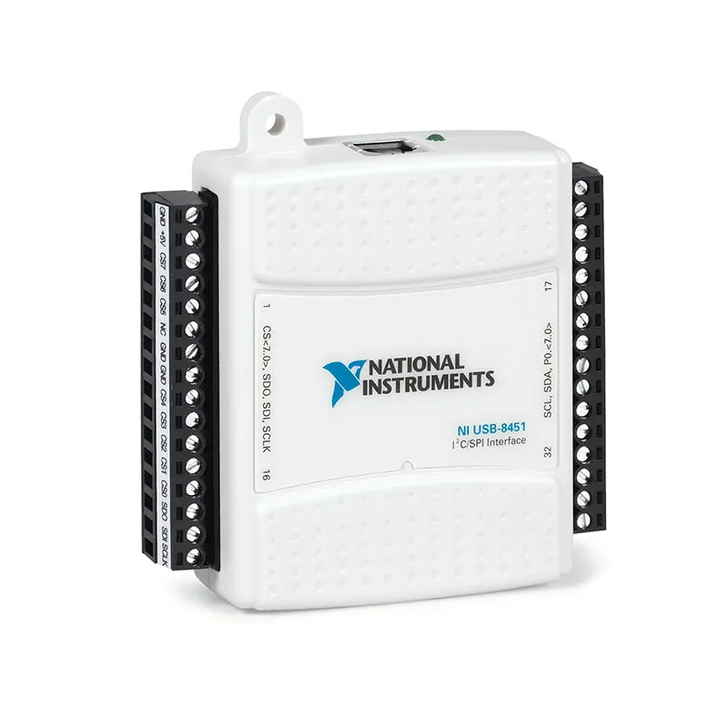
The NI USB-8451 is a USB I²C, SPI and digital I/O interface designed for communicating with integrated circuits, sensors, memory devices and embedded-system peripherals. It allows a computer to generate serial commands and read device responses without developing a dedicated microcontroller interface.
The USB-8451 supports SPI clock rates up to 12 MHz and I²C clock rates up to 250 kHz. Eight chip-select outputs simplify communication with multiple SPI peripherals, while eight individually configurable digital I/O lines support reset, interrupt, status and general control signals.
Key Features of the USB-8451
- USB-to-I²C and USB-to-SPI interface
- 12 MHz maximum SPI clock rate
- 250 kHz maximum I²C clock rate
- I²C and SMBus device compatibility
- Eight SPI chip-select outputs
- Eight individually configurable digital I/O lines
- Push-pull or open-drain DIO operation
- Programmable I/O reference voltage
- Fixed 5 V auxiliary output
- USB Full-Speed interface
- USB bus-powered operation
- Two removable 16-position terminal connectors
- NI-845x driver support
USB-8451 Technical Specifications
| Product Model | USB-8451 |
|---|---|
| Product Type | USB I²C, SPI and digital I/O interface |
| SPI Role | Controller/master interface |
| Maximum SPI Clock | 12 MHz |
| SPI Transfer Size | 8 bits |
| SPI Chip Selects | 8 |
| Maximum I²C Clock | 250 kHz |
| I²C Modes | Standard mode and supported rates through 250 kHz |
| Fast Mode Plus | Not supported |
| High-Speed I²C Mode | Not supported |
| Digital I/O Lines | 8 |
| DIO Direction | Individually software selectable |
| DIO Output Type | Push-pull or open-drain |
| USB Interface | USB Full-Speed, 12 Mb/s |
| Auxiliary Supply | 5 V output |
| I/O Connectors | 2 × 16-position screw-terminal headers |
| USB Connector | USB Type-B receptacle |
| Weight | 84 g |
| Operating Temperature | 0°C to 45°C |
I2C Communication
The I²C interface uses open-drain clock and data lines and supports standard clock selections from 32 kHz through 250 kHz. Software-configurable pull-up functionality and the programmable reference voltage help adapt the interface to different peripheral logic levels.
The USB-8451 is also compatible with many SMBus devices. Engineers should verify device addressing, voltage, pull-up resistance, clock-stretching behavior and protocol-specific timing before connecting a target circuit.
SPI Communication
The SPI interface supplies SCLK, MOSI and MISO signals and supports clock selections up to 12 MHz. Eight chip-select outputs allow software to address several peripherals without adding a separate external decoder.
Before communication begins, configure the correct clock polarity, clock phase, bit order, chip-select behavior and clock rate specified by the peripheral manufacturer.
Eight Digital I/O Lines
The eight DIO lines can be independently configured as inputs or outputs. They can monitor interrupt and status signals or control reset, enable, write-protect and mode-selection pins associated with the serial device.
Digital lines are intended for logic-level interfacing. External buffer or driver circuitry is required when controlling relays, lamps, motors or other higher-current loads.
USB-8451 Part Number and Accessories
| Item | Description |
|---|---|
| USB-8451 | Enclosed USB I²C/SPI interface with screw-terminal connections |
| USB-8451 OEM | Board-level version intended for integration into custom systems |
| 16-Position Terminal Plugs | Provide field wiring access to serial and digital signals |
| USB Type-A to Type-B Cable | Provides host communication and operating power |
| Logic-Level Adapter | Used when the target voltage or electrical interface requires translation |
Confirm whether the application requires the enclosed USB-8451 or the OEM version. Their mechanical connectors and intended installation methods are different.
USB-8451 Applications
- I²C sensor testing
- SPI peripheral communication
- EEPROM programming and verification
- Flash-memory testing
- Power-management IC configuration
- Embedded-controller validation
- Device register access
- Production programming stations
- Prototype debugging
- Automated functional testing
Sensor and IC Evaluation
The interface can configure registers and collect data from temperature sensors, accelerometers, ADCs, DACs and other serial peripherals. Its digital lines can simultaneously control reset or monitor a data-ready interrupt.
EEPROM and Memory Programming
Automated software can write configuration data to compatible I²C or SPI memory, read it back and verify the result. Device voltage, addressing, page size and write-cycle timing must be configured correctly.
USB-8451 Installation Workflow
Step 1: Install the NI-845x Driver
Install a compatible NI-845x driver before connecting the interface to the host computer.
Step 2: Connect and Identify the Hardware
Connect the USB cable, allow the computer to detect the device and confirm its presence in NI Measurement & Automation Explorer.
Step 3: Configure the Electrical Interface
Determine the target logic voltage and configure the reference voltage and pull-up arrangement before wiring the device.
Step 4: Connect the Peripheral
Connect the required I²C or SPI signals and establish a common ground. Keep high-speed SPI wiring short and avoid unterminated branches.
Step 5: Test a Basic Transaction
Start with a low clock rate and perform a known register-read or identification transaction before building the complete automated sequence.
USB-8451 Troubleshooting
The peripheral does not acknowledge an I2C command
Check the device address, common ground, pull-up resistors, reference voltage and whether the target uses a shifted or unshifted address representation.
SPI data is incorrect
Verify clock polarity, clock phase, bit order, chip-select assignment and maximum peripheral clock rate. Reduce the clock rate while diagnosing signal-integrity problems.
The DIO line cannot drive the connected load
Use an external logic buffer or power driver. USB-8451 digital lines are intended for communication and logic control rather than powering external loads.
Communication is intermittent
Shorten wiring, verify the ground connection and examine the signals with an oscilloscope or logic analyzer. Incorrect pull-up resistance can cause slow I²C edges.
The USB-8451 is not detected
Check the USB cable, port and NI-845x installation. Avoid unpowered hubs and test the interface on another known-good USB port.
USB-8451 Comparison
| Model | Interface | Best Suited For |
|---|---|---|
| USB-8451 | 250 kHz I²C, 12 MHz SPI, 8 DIO | General embedded-device communication |
| USB-8451 OEM | Same interface in board-level format | Integration into custom fixtures and products |
| USB-8452 | Higher-performance I²C/SPI interface | Applications requiring faster communication or advanced streaming |
| USB-6000 | Analog input, DIO and counter | Voltage measurement rather than serial-bus communication |
USB-8451 Frequently Asked Questions
What protocols does the USB-8451 support?
It supports I²C, compatible SMBus communication, SPI and static digital I/O.
What is the maximum SPI clock rate?
The specified maximum SPI clock rate is 12 MHz.
What is the maximum I2C clock rate?
The I²C interface supports selected clock rates up to 250 kHz.
How many SPI peripherals can be selected directly?
The device provides eight dedicated chip-select outputs.
Does the USB-8451 replace a logic analyzer?
No. It generates and receives protocol transactions, while a logic analyzer primarily captures and analyzes existing digital activity.
Request a Quote for the USB-8451
Contact us for availability and pricing for the NI USB-8451 I²C/SPI interface. We can also assist with USB cables, connector plugs, OEM integration and other NI test and communication products.















