




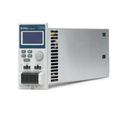
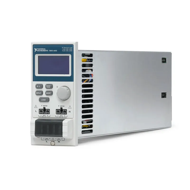
RMX-4003 2-Channel 100 W DC Electronic Load Module
The RMX-4003 is a dual-channel programmable DC electronic load module designed for power-supply development, battery testing, DC converter characterization and automated production testing. Each channel can sink as much as 100 W, 20 A and 80 VDC.
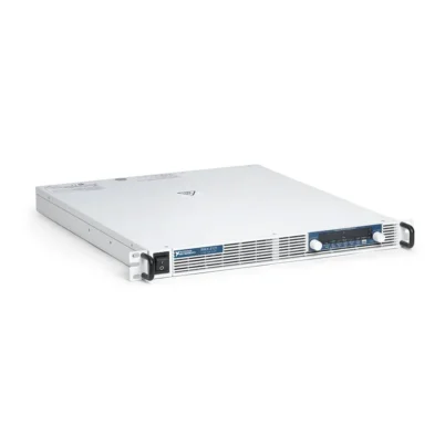
The RMX-4003 installs in a compatible RMX-4000 or RMX-4002 electronic-load mainframe. The mainframe provides power, cooling, front-panel operation and remote communication for the installed load modules.
Constant-current, constant-voltage, constant-resistance and constant-power modes allow the RMX-4003 to simulate different electrical loads. Dynamic current and resistance operation helps engineers evaluate the transient response of power supplies and other DC sources.
Key Features of the RMX-4003
- Two independent electronic-load channels
- 100 W maximum input power per channel
- 200 W total installed load capacity
- 0 V to 80 VDC input-voltage range
- 0 A to 20 A current range per channel
- Constant-current operating mode
- Constant-voltage operating mode
- Constant-resistance operating mode
- Constant-power operating mode
- Combined constant-voltage and constant-current control
- Static and dynamic load operation
- Programmable current slew rate
- Two programmable dynamic-load levels
- Voltage, current and power measurement
- Short-circuit load simulation
- Go/No-Go limit testing
- Sequence and automated test capability
- Parallel-channel operation for increased capacity
- Remote control through the installed mainframe
- NI RMX-400x Loads instrument-driver support
RMX-4003 Technical Specifications
| Product Model | RMX-4003 |
|---|---|
| Part Number | 786529-01 |
| Product Type | Dual-channel programmable DC electronic load module |
| Number of Channels | 2 |
| Maximum Input Power | 100 W per channel |
| Total Module Power | 200 W across two channels |
| Input-Voltage Range | 0 V to 80 VDC |
| Maximum Current | 20 A per channel |
| Primary Operating Modes | CC, CV, CV+CC, CR and CP |
| Dynamic Operating Modes | Dynamic CC and CR |
| Maximum Current Accuracy | Up to ±0.4% of full scale, depending on range and operating conditions |
| Current Slew-Rate Range | Approximately 3.2 mA/µs to 800 mA/µs, depending on range |
| Measurements | Voltage, current and calculated power |
| Compatible Mainframes | RMX-4000 and RMX-4002 |
| Remote Interfaces | Provided by the mainframe through USB, RS232 and supported communication options |
| Software Driver | NI RMX-400x Loads instrument driver |
| Minimum Legacy Driver Requirements | LabVIEW 8.2 or later and NI-VISA 5.0 or later |
| Calibration Interval | 1 year for supported ECUTS maintenance applications |
The 80 V, 20 A and 100 W ratings apply simultaneously as operating limits. A channel cannot sink 80 V at 20 A because that operating point would equal 1600 W and exceed the 100 W power rating.
At an 80 V input, a 100 W channel can sink approximately 1.25 A. The full 20 A current is available only at lower input voltages and within the module’s safe operating area.
RMX-4003 Part Number and Required Mainframes
| Item | Part Number | Description |
|---|---|---|
| RMX-4003 | 786529-01 | Two-channel, 100 W per channel, 80 V, 20 A DC electronic load module |
| RMX-4000 | Model dependent | Two-slot electronic-load mainframe for RMX-400x modules |
| RMX-4002 | 786528-01 | Four-slot electronic-load mainframe for RMX-400x modules |
The RMX-4003 is not a standalone benchtop instrument. It must be installed in a compatible mainframe before it can operate.
Verify whether a quotation includes only the RMX-4003 module or a complete system with the mainframe, communication interface and required test cables.
Dual-Channel Electronic Load Architecture
The RMX-4003 contains two independently controlled load channels. Each channel has its own programmable load settings and can be connected to a separate power-source output.
This architecture is useful for testing multi-output power supplies, DC converters, automotive controllers and devices containing two independent DC rails.
Each channel can measure its applied voltage and absorbed current. The system can also calculate input power so test software can verify whether the source remains within the expected operating limits.
100 W Input Power per Channel
Each channel can dissipate as much as 100 W of DC input power. The complete module therefore provides 200 W of aggregate load capacity when both channels operate within their individual ratings.
The maximum allowable current changes with input voltage. At higher voltage, the 100 W limit reduces the current that can be absorbed. At lower voltage, current is limited by the channel’s 20 A rating and minimum operating-voltage characteristics.
Test programs should evaluate voltage, current and power together instead of treating each maximum specification as an independently available operating point.
0 V to 80 VDC Input Range
The RMX-4003 supports DUT voltages up to 80 VDC on each channel. This range covers many industrial, telecommunications, automotive and laboratory DC power systems.
Typical test voltages can include 5 V, 12 V, 24 V and 48 V power rails. Always verify the actual transient and open-circuit voltage of the source because it must remain below the module’s maximum input rating.
20 A Current Capability
Each electronic-load channel can sink as much as 20 A within its voltage, power and safe-operating-area limitations.
This current rating supports testing lower-voltage power sources that deliver more current than conventional low-power benchtop loads can absorb.
Use short, adequately sized conductors for higher-current testing. Cable resistance creates voltage drop, heat and measurement differences between the DUT output and load input.
Constant-Current Mode
In constant-current mode, the RMX-4003 sinks the programmed current while the DUT voltage varies within the allowable operating range.
This mode is commonly used to test output regulation, current capability, battery discharge behavior and power-supply protection circuits.
For example, an engineer can gradually increase the load current while monitoring the DUT voltage to identify the point where voltage regulation begins to degrade.
Constant-Voltage Mode
In constant-voltage mode, the load adjusts its current consumption to regulate the input terminals at a programmed voltage.
This operating mode is useful for current-source testing, charger evaluation and other applications where the load must maintain a particular terminal voltage.
The combined CV+CC function can include a current limit while operating in constant-voltage mode, helping prevent the load from exceeding a defined current level.
Constant-Resistance Mode
Constant-resistance mode causes the current to change in proportion to the applied voltage. The electronic load therefore behaves like a programmable resistor within its operating limits.
This mode can simulate heaters, lamps and other approximately resistive loads without requiring a large collection of fixed power resistors.
Constant-Power Mode
In constant-power mode, the RMX-4003 adjusts current as the DUT voltage changes so that the channel absorbs approximately the programmed power.
This behavior can simulate DC-powered electronic equipment and converters that attempt to maintain their input power as the supply voltage changes.
A constant-power load may demand additional current when the input voltage falls. Configure suitable current and power limits to prevent an unstable interaction with the DUT.
Static Load Testing
Static operation maintains a selected current, voltage, resistance or power value until a new value is programmed.
Engineers can use static loading to measure DC output accuracy, load regulation, efficiency, thermal behavior and steady-state operation at multiple load points.
Dynamic Load Testing
Dynamic constant-current and constant-resistance modes alternate between two programmed load levels. The dwell time and transition behavior can be configured according to the required test profile.
Dynamic operation is useful for verifying how a power supply responds when its load changes rapidly. A digitizer or oscilloscope can capture voltage deviation, overshoot, undershoot and recovery time.
Programmable Current Slew Rate
The current slew rate controls how quickly the electronic load transitions between programmed current levels. The RMX-4003 supports selectable slew rates according to the chosen range and operating mode.
A slower transition can represent gradually changing equipment, while a faster transition can simulate a rapidly enabled digital or electromechanical load.
Actual DUT behavior also depends on cable inductance, source impedance, output capacitance and measurement-probe placement.
Parallel-Channel Operation
The two RMX-4003 channels can be grouped or operated in parallel according to the official connection procedure. This can provide as much as 200 W of combined load capacity and increased current capability for one DUT output.
Parallel operation requires compatible channel settings and properly sized, balanced wiring. Unequal cable resistance can cause one channel to absorb more current than the other.
Multiple compatible load modules can also be combined in a larger RMX-4002 four-slot mainframe when additional power or current capacity is required.
Voltage, Current and Power Measurements
The RMX-4003 can report the voltage and current measured at each channel. Power values are calculated from the measured electrical conditions.
These internal measurements support automated functional testing and Go/No-Go evaluation. For high-accuracy verification, an external calibrated digital multimeter or current-measurement device may still be required.
Short-Circuit Simulation
A short function allows the load to apply a low-impedance condition according to the selected operating mode and range. This helps evaluate power-supply current limiting and short-circuit protection.
Before applying the short function, verify that the DUT, electronic load, wiring and protective devices can safely tolerate the resulting current and stored energy.
Go/No-Go Testing
The RMX-400x system can compare measured values with programmed upper and lower limits. This enables automated pass/fail evaluation during production and incoming inspection.
Test results can be read through the remote interface or communicated using the mainframe’s Go/No-Go status function.
Sequence Testing
Programmable sequences allow the electronic load to apply a series of operating points without requiring the host computer to send every individual transition in real time.
A sequence can simulate a product’s changing power consumption, exercise a power source at different loads or perform a repeatable multi-step validation routine.
RMX-4000 Mainframe Integration
The RMX-4000 provides two slots for compatible RMX-400x load modules. It is suitable for a smaller system requiring up to four RMX-4003 channels.
Select the two-slot mainframe when rack space and acquisition requirements do not justify the larger four-slot configuration.
RMX-4002 Mainframe Integration
The RMX-4002 provides four module slots. Installing four RMX-4003 modules creates as many as eight independently programmable 100 W load channels.
The RMX-4002 can also combine the RMX-4003 with high-current or high-voltage modules when the DUT contains power rails with different electrical requirements.
Remote Control and Automation
The RMX-4003 is controlled remotely through the communication resources of its RMX-4000 or RMX-4002 mainframe. Supported system interfaces include USB, RS232 and available GPIB configurations.
Remote commands can configure load modes, ranges, current, voltage, resistance, power, dynamic timing and measurement queries.
Automated control is valuable for production testing, long-duration validation and test sequences containing many load conditions.
NI RMX-400x Loads Driver
NI provides the RMX-400x Loads project-style instrument driver for LabVIEW. It supports the RMX-4003, RMX-4004, RMX-4005 and RMX-4006 load modules.
NI lists LabVIEW 8.2 or later and NI-VISA 5.0 or later as the minimum requirements for the legacy driver. Verify compatibility with the selected operating system and current LabVIEW release before deployment.
Power-Supply Development
The RMX-4003 can apply controlled loads while engineers measure power-supply output voltage, regulation, ripple, noise and transient response.
Its two channels allow simultaneous testing of two output rails. This can reveal cross-regulation behavior that may not appear when each power rail is tested separately.
Multi-Output Power-Supply Testing
Many power supplies provide several output voltages, such as 5 V, 12 V and 24 V. Multiple RMX-4003 channels can load these outputs independently.
Test software can change one channel while maintaining a steady load on another, helping characterize interactions between different outputs.
Battery Discharge Testing
Constant-current, constant-resistance and constant-power modes can be used to discharge batteries under controlled conditions.
An automated sequence can monitor battery voltage and stop the load when the specified discharge endpoint is reached. The fixture should include independent protection against overdischarge, reverse polarity and unsafe battery temperature.
The RMX-4003 is not regenerative. Absorbed battery energy is converted into heat and removed through the mainframe’s cooling system.
Battery Charger Testing
Constant-voltage operation can help simulate a battery terminal during charger development. Other modes can evaluate charger current delivery, regulation and protection behavior.
Battery simulation requirements vary significantly. Confirm that the RMX-4003 operating modes and response characteristics are appropriate for the charger before using it as a replacement for a real battery.
DC-DC Converter Testing
The two load channels can test separate converter outputs or two devices in parallel. Engineers can measure efficiency, output regulation, protection thresholds and transient performance.
The 80 V range covers many industrial, communications and automotive DC converter applications.
Automotive ECU Testing
The RMX-4003 can simulate resistive or electronic loads connected to automotive controller outputs. Two independent channels can represent separate actuators or vehicle electrical loads.
The module does not directly reproduce every characteristic of a motor, solenoid, lamp or other reactive load. Additional circuitry may be required when the test must reproduce inductance, capacitance, inrush current or back electromotive force.
Production Functional Testing
In production environments, the RMX-4003 can apply repeatable loads and compare measured voltage or current against predefined limits.
Automated control reduces manual adjustment and helps ensure that every DUT is evaluated under the same electrical conditions.
RMX-4003 Applications
- DC power-supply development
- Multi-output power-supply testing
- DC-DC converter validation
- Battery discharge testing
- Battery charger testing
- Power-adapter evaluation
- Automotive ECU output testing
- Telecommunications power testing
- Dynamic load-transient testing
- Cross-regulation measurements
- Production Go/No-Go testing
- Burn-in and reliability testing
- Automated test equipment
- Laboratory power-source characterization
RMX-4003 Installation
Step 1: Select the Mainframe
Choose an RMX-4000 two-slot or RMX-4002 four-slot mainframe according to the required total number of load modules and channels.
Step 2: Turn Off Mainframe Power
Turn off and disconnect the mainframe before installing or removing the RMX-4003. Hot insertion is not supported.
Step 3: Install the Load Module
Slide the RMX-4003 into an available slot until its connectors are fully seated. Secure the module according to the mainframe installation instructions.
Step 4: Connect the DUT
Connect each DUT output to the correct channel terminals with the required polarity. Use appropriately rated cables and minimize connection resistance.
Step 5: Configure the Load
Select the required channel, operating mode, range, load value and protection settings before enabling the load input.
Step 6: Verify Operation
Begin with a conservative load value and confirm the measured voltage, current and power before increasing the load.
RMX-4003 Troubleshooting
The RMX-4003 Is Not Recognized
Turn off the mainframe and verify that the module is fully installed in a compatible slot. Inspect the module and mainframe connectors for damage or contamination.
The Channel Does Not Sink Current
Confirm that the selected channel is enabled and that the DUT is connected with correct polarity. Verify the operating mode, current setting and selected range.
The DUT voltage may also be below the level required for the programmed current and operating mode.
The Channel Cannot Reach 20 A
Check the channel’s 100 W power limit. For example, at 12 V the maximum current permitted by the power rating is approximately 8.33 A, even though the channel current rating is 20 A.
The complete operating point must remain within the module’s voltage, current, power and safe-operating-area limits.
The Input Power Exceeds 100 W
Reduce the programmed current or the DUT voltage. Each channel is limited to 100 W, and exceeding that value can activate load protection.
The Voltage Measurement Is Lower Than Expected
Check the DUT output terminals and cable resistance. High current through long or undersized conductors can create substantial voltage drop before the load input.
Dynamic Test Results Are Unstable
Use short, low-inductance cables and verify the programmed current slew rate. Check DUT output capacitance, source stability and oscilloscope probe placement.
The Module Reports Overtemperature
Disable the load and allow the system to cool. Check the RMX mainframe fans, intake filter, exhaust clearance, ambient temperature and power dissipated by adjacent modules.
Remote Communication Does Not Work
Check the mainframe interface, cable, address and NI-VISA resource. Confirm that the RMX-400x Loads driver is installed in the correct LabVIEW instrument-library directory.
Parallel Channels Do Not Share Current Evenly
Confirm that both channels use compatible settings. Use matched cables with similar length and conductor size to reduce differences in connection resistance.
RMX-4003 Comparison with Similar Electronic Load Modules
| Model | Channel Configuration | Best Suited For |
|---|---|---|
| RMX-4003 | 2 channels, 100 W per channel, 80 V, 20 A | Balanced dual-channel and multi-output testing |
| RMX-4004 | 2 channels, 30 W/5 A and 250 W/40 A, 80 V | One main output plus one auxiliary output |
| RMX-4005 | 1 channel, 350 W, 80 V, 70 A | Low-voltage, high-current source testing |
| RMX-4006 | 1 channel, 350 W, 500 V, 10 A | High-voltage DC source testing |
RMX-4003 vs RMX-4004
The RMX-4003 provides two identical 100 W, 20 A channels. The RMX-4004 provides one 30 W, 5 A channel and one 250 W, 40 A channel.
Choose the RMX-4003 when two outputs require similar loading capacity. Choose the RMX-4004 when one main output requires substantially more power and current than the auxiliary output.
RMX-4003 vs RMX-4005
The RMX-4003 provides two 100 W channels with 20 A maximum current per channel. The RMX-4005 provides one 350 W channel capable of sinking as much as 70 A.
Select the RMX-4003 for higher channel density. Select the RMX-4005 for a single low-voltage source requiring more current or power.
RMX-4003 vs RMX-4006
The RMX-4003 supports two channels at up to 80 V, while the RMX-4006 provides one 350 W channel rated for input voltages up to 500 V.
Select the RMX-4003 for low- and medium-voltage multi-channel testing. Select the RMX-4006 when the source voltage exceeds 80 V.
Selecting the Right RMX-400x Load Module
Choose the RMX-4003 when the test requires two similar channels, each operating within 80 V, 20 A and 100 W.
Choose the RMX-4004 for an asymmetric dual-output DUT, the RMX-4005 for low-voltage high-current testing or the RMX-4006 for voltages as high as 500 V.
Calculate the complete load operating point before selecting a module. Maximum voltage, current and power cannot necessarily be used simultaneously.
Recommended Related Products
- RMX-4000 2-Slot Electronic Load Mainframe
- RMX-4002 4-Slot Electronic Load Mainframe
- RMX-4004 Dual-Channel Electronic Load Module
- RMX-4005 350 W 70 A Electronic Load Module
- RMX-4006 350 W 500 V Electronic Load Module
- RMX-4104 Programmable DC Power Supply
- RMX-4124 1500 W 30 V Programmable DC Power Supply
- View More National Instruments Products
Why Choose the RMX-4003?
- Provides two independently controlled load channels
- Supports 100 W, 80 V and 20 A per channel
- Offers multiple programmable load modes
- Supports dynamic current and resistance testing
- Measures channel voltage, current and power
- Can test two power outputs simultaneously
- Can be combined with additional RMX-400x modules
- Supports automated LabVIEW control
- Fits both two-slot and four-slot RMX mainframes
- Provides flexible power-source characterization
Frequently Asked Questions
What is the RMX-4003?
The RMX-4003 is a dual-channel programmable DC electronic load module used with RMX-4000 or RMX-4002 mainframes.
What is the RMX-4003 part number?
The standard NI part number for the RMX-4003 is 786529-01.
How many channels does the RMX-4003 provide?
It provides two independently programmable electronic-load channels.
What is the maximum power?
Each channel can absorb as much as 100 W, providing 200 W of total module capacity when both channels operate within their individual ratings.
What is the maximum input voltage?
The maximum specified input voltage is 80 VDC per channel.
What is the maximum current?
Each channel can sink as much as 20 A within its 100 W power rating and safe operating area.
Can the RMX-4003 sink 20 A at 80 V?
No. That operating point would equal 1600 W. Each channel is limited to 100 W, so the maximum current at 80 V is approximately 1.25 A.
Which mainframe is required?
The RMX-4003 operates in either an RMX-4000 two-slot mainframe or an RMX-4002 four-slot mainframe.
Which load modes are supported?
The platform supports constant-current, constant-voltage, constant-resistance and constant-power modes, along with dynamic current and resistance operation.
Can the two channels be connected in parallel?
Yes. Compatible channels can be grouped or connected in parallel according to the official wiring instructions to increase total current and power capacity.
Is the RMX-4003 a power supply?
No. It absorbs DC power from a source. It does not generate DC output power.
Which software controls the RMX-4003?
NI provides the RMX-400x Loads instrument driver for LabVIEW. Remote commands are sent through the communication interface of the RMX mainframe.
Request a Quote for the RMX-4003
Contact us for current availability, lead time and project pricing for the RMX-4003 2-Channel 100 W DC Electronic Load Module, part number 786529-01. We can also help select an RMX-4000 or RMX-4002 mainframe and compare compatible load modules for your required voltage, current, power and channel count.















