






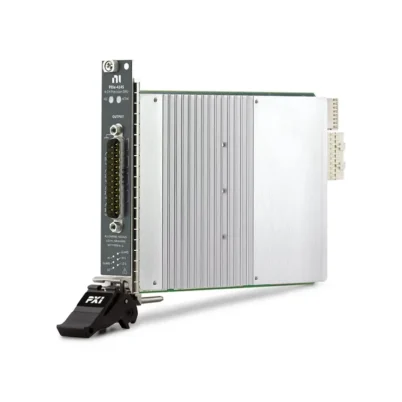
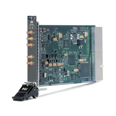
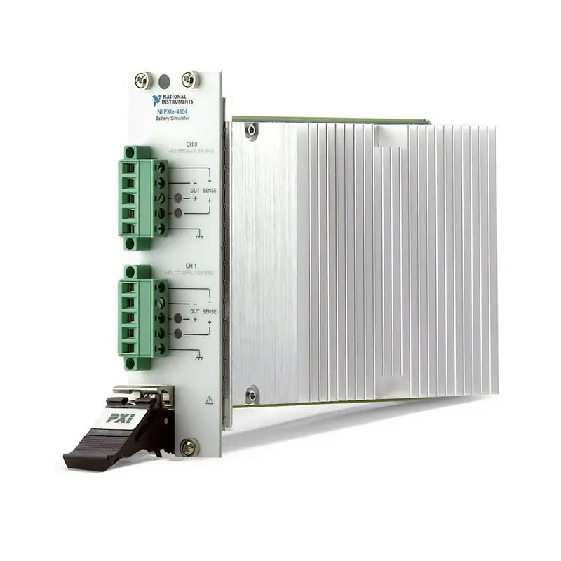
PXIe-4154 2-Channel 8 V ±3 A Battery Simulator
The PXIe-4154 is a two-channel PXI Express programmable power supply specifically designed for battery simulation, charger simulation and mobile-device power testing. It combines fast source-and-sink operation, programmable output resistance and integrated voltage and current measurement in a two-slot PXI Express module.
Channel 0 operates as a battery simulator with a 0 V to 6 V output range and current capability up to 3 A. Channel 1 operates as a charger simulator with a 0 V to 8 V output range and source current up to 1.5 A. The channels can be used together to reproduce battery-powered operating conditions while a device is connected to a charger.
The PXIe-4154 provides a maximum measurement sampling rate of 200 kS/s, current sensitivity down to 1 µA and four-wire remote sensing. Its fast transient mode can recover to within ±20 mV in less than 20 µs after a specified load-current change, making it suitable for testing RF power amplifiers, cellular handsets and other devices with rapidly changing current consumption.
Key Features of the PXIe-4154
- Two independently controlled power-supply channels
- Dedicated battery simulator and charger simulator channels
- 0 V to 6 V battery simulator output
- Up to 3 A battery-channel source current
- Approximately 3.1 A battery-channel sink capability
- 0 V to 8 V charger simulator output
- Up to 1.5 A charger-channel source current
- Two-quadrant source-and-sink operation
- Programmable output resistance up to 1 Ω
- 1 µA current measurement sensitivity
- 200 kS/s maximum measurement sampling rate
- Less than 20 µs fast transient recovery
- Four-wire remote sensing on both channels
- Integrated voltage and current measurement
- Channel-to-channel and channel-to-ground isolation
- PXI hardware trigger support
- NI-DCPower and InstrumentStudio compatibility
PXIe-4154 Technical Specifications
| Product Model | PXIe-4154 |
|---|---|
| Part Number | 781155-01 |
| Product Type | PXI Express programmable power supply and battery simulator |
| Number of Channels | 2 |
| Channel 0 Function | Battery simulator |
| Channel 0 Voltage Range | 0 V to 6 V |
| Channel 0 Current Source Ranges | 30 mA and 3 A |
| Channel 0 Maximum Source Current | 3 A |
| Channel 0 Sink Current | Up to approximately 3.1 A, typical and operating-point dependent |
| Channel 1 Function | Charger simulator |
| Channel 1 Voltage Range | 0 V to 8 V |
| Channel 1 Maximum Source Current | 1.5 A |
| Channel 1 Sink Current | 0.1 A typical fixed limit |
| Combined Source Current Limit | 3.1 A maximum across both channels |
| Operating Quadrants | Two-quadrant source and sink operation |
| Programmable Output Resistance | Up to 1 Ω nominal on Channel 0 |
| Output Resistance Resolution | 1 mΩ nominal |
| Channel 0 Voltage Measurement Resolution | 100 µV nominal |
| Channel 0 Current Measurement Resolution | 1 µA on the 30 mA range; 100 µA on the 3 A range |
| Channel 1 Voltage Measurement Resolution | 150 µV nominal |
| Channel 1 Current Measurement Resolution | 50 µA nominal |
| Maximum Sampling Rate | 200 kS/s |
| Maximum Source Update Rate | 1,850 updates/s, characteristic |
| Typical Settling Time | 500 µs to within 1% for a specified 1 V step |
| Fast Transient Recovery | Within ±20 mV in less than 20 µs for the specified load step |
| Channel 0 Normal-Mode Noise | Less than 1 mV RMS typical |
| Channel 1 Normal-Mode Noise | Less than 2 mV RMS typical |
| Remote Sensing | Four-wire remote sense |
| Maximum Remote-Sense Lead Drop | Up to 1 V per lead, operating-point dependent |
| Isolation | 60 VDC CAT I, channel-to-channel and channel-to-ground |
| Trigger Lines | PXI trigger lines 0 through 7 |
| Bus Interface | PXI Express |
| Front-Panel Connectors | Phoenix Contact COMBICON, 5.08 mm, five-position |
| Module Format | 3U, two-slot PXI Express module |
| Dimensions | 4.0 × 13.0 × 21.6 cm |
| Weight | 565 g nominal |
| Software Support | NI-DCPower, LabVIEW and InstrumentStudio |
| Lifecycle Status | No longer available from NI |
PXIe-4154 Part Number and Connection Information
| Item | Part Number | Description |
|---|---|---|
| PXIe-4154 | 781155-01 | Two-channel, 8 V, ±3 A PXI Express battery simulator and programmable power supply |
| PXIe-4154 Connector Type | Verify with supplied hardware | Five-position Phoenix Contact COMBICON connector for each output interface |
Before ordering a replacement module, confirm that the required removable connector plugs, backshells and wiring are included. The output and remote-sense conductors must be sized for the expected current and arranged to minimize resistance and inductance.
Dedicated Battery Simulator Channel
Channel 0 is optimized for simulating a single lithium-ion battery cell. It can program voltages between 0 V and 6 V while sourcing current up to 3 A or sinking current from the connected device.
This bidirectional behavior allows the PXIe-4154 to reproduce both battery discharge and charging conditions. The same channel can power a device during active operation and absorb returned current when the DUT drives energy back toward the simulated battery.
The sink-current capability depends on the programmed voltage and terminal operating point. At lower terminal voltages, the maximum available sink current may decrease, so the expected voltage and current profile should be checked against the official quadrant diagram.
Charger Simulator Channel
Channel 1 provides a 0 V to 8 V output range and can source as much as 1.5 A. It can simulate an external charger, AC adapter or USB-derived power source connected to a battery-operated device.
Using both channels together allows engineers to examine how a product transitions between battery power and charger power. Test software can vary the battery voltage, charger voltage and current limits while measuring how the device manages its internal power path.
The total source current supplied by both channels cannot exceed 3.1 A. Test sequences must account for this combined limit when the battery and charger simulator channels operate simultaneously.
Two-Quadrant Source-and-Sink Operation
The PXIe-4154 supports two-quadrant operation, allowing it to source current to a DUT and sink current returned from the DUT. This is important for realistic battery simulation because rechargeable products can draw or return energy depending on their operating state.
Conventional unidirectional power supplies generally cannot absorb reverse current. A two-quadrant supply can respond more accurately when testing charging circuits, power-path controllers and products with regenerative behavior.
Programmable Output Resistance
Channel 0 provides programmable output resistance up to 1 Ω with nominal 1 mΩ resolution. This feature can simulate the internal resistance of a battery cell, including the increased voltage drop that occurs as load current rises.
Battery voltage at the DUT can therefore respond dynamically to its current consumption instead of remaining at an ideal fixed voltage. Engineers can use this capability to evaluate behavior with a fresh battery, an aged battery or a battery operating near its discharge limit.
Programmable output resistance can also help identify brownout thresholds, unexpected resets and RF-performance degradation caused by battery impedance.
Fast Transient Response
Mobile and RF devices can change current consumption rapidly. A cellular transmitter or RF power amplifier may transition from a low-current standby state to a high-current transmit state within a short interval.
In fast transient mode, Channel 0 can recover to within ±20 mV in less than 20 µs following the specified 0.1 A to 1.5 A load-current step. The typical transient voltage dip is less than 70 mV under the stated test conditions.
This response helps maintain a stable supply voltage during fast load changes and reduces the risk that the power source itself will distort the DUT’s measured behavior.
Integrated Voltage and Current Measurement
Both channels include voltage and current measurement capabilities. This allows the PXIe-4154 to power the DUT and record its electrical consumption without requiring a separate current-measurement instrument for many applications.
Channel 0 provides 30 mA and 3 A current ranges. The 30 mA range offers nominal 1 µA resolution for measuring standby and quiescent current, while the 3 A range supports measurement of higher active-mode current.
Range selection should match the expected current profile. The lower range provides greater sensitivity, while the higher range accommodates transmit bursts and other high-current operating states.
200 kS/s Measurement Sampling
The PXIe-4154 can acquire measurements at rates up to 200 kS/s. High-speed sampling helps capture current pulses, device startup behavior, transmit bursts and short-duration changes that may not be visible with slower power-supply measurements.
Test software can correlate current consumption with DUT operating modes, RF activity and digital control events. The actual measurement configuration should balance sampling rate, record length, averaging and noise performance.
Four-Wire Remote Sensing
Four-wire remote sensing allows the PXIe-4154 to regulate voltage at the DUT connection rather than only at the module connector. Separate sense conductors measure the voltage after the drop produced by the force leads.
This capability is especially valuable at higher current because cable and fixture resistance can cause a significant difference between the programmed voltage and the voltage actually reaching the DUT.
Remote-sense wires should connect close to the DUT power terminals and should not carry load current. Correct polarity and secure connections are essential because an open or incorrectly connected sense lead can affect voltage regulation.
Low-Noise Output
Channel 0 provides typical normal-mode noise below 1 mV RMS when tested with a resistive load over the specified bandwidth. Channel 1 provides typical noise below 2 mV RMS.
Low output noise is important when powering RF amplifiers, wireless transceivers and sensitive analog circuits. External wiring, grounding, shielding and the PXI chassis environment also contribute to the noise measured at the DUT.
Isolated Output Channels
The two output channels are isolated from chassis ground and isolated from each other. The specified isolation voltage is 60 VDC CAT I.
Channel isolation provides flexibility when configuring battery and charger connections, but it does not permit connection to mains circuits. The PXIe-4154 is intended for Measurement Category I signal circuits only.
Overvoltage Protection
Each channel includes overvoltage protection. The output is disconnected if the voltage at the positive output terminal rises approximately 2.5 V above the programmed value under the specified conditions.
Test fixtures should still include any additional fusing, current limiting or protection required by the DUT. Software limits and instrument protection should not be the only safeguards used with expensive prototypes or high-energy external circuits.
PXI Hardware Triggering
The PXIe-4154 supports input and output triggering through PXI trigger lines 0 through 7. Supported input trigger functions include start, source, sequence advance and measurement triggering.
Hardware triggering allows voltage changes and measurements to be coordinated with oscilloscopes, RF instruments, digital pattern instruments and other PXI modules. This is useful when power consumption must be measured at a precise point in a test sequence.
Battery-Powered Device Testing
The PXIe-4154 can reproduce changing battery conditions without repeatedly charging, discharging or replacing physical battery cells. Test software can sweep the simulated battery voltage and output resistance while monitoring device operation.
This helps engineers verify startup voltage, shutdown thresholds, low-battery warnings, power-management behavior and recovery after a temporary voltage drop.
RF Power Amplifier Testing
RF power amplifiers can draw fast, high-amplitude current pulses. The PXIe-4154’s transient response and high-speed measurement capabilities make it suitable for observing how supply conditions affect output power, efficiency and signal quality.
The module can be synchronized with PXI RF generators and analyzers so that supply-current measurements correspond to defined RF bursts or modulation events.
Cellular Handset Testing
Mobile devices operate through standby, receive, processing and transmit states with very different current requirements. The PXIe-4154 can measure these transitions while maintaining a controlled simulated battery voltage.
Programmable output resistance can be used to reproduce the voltage droop of an aged or partially discharged battery during a high-current transmit burst.
Power-Management IC Validation
The module can support validation of power-management integrated circuits, battery chargers and power-path controllers. Engineers can program battery and charger conditions independently and observe how the circuit selects, regulates and transfers power.
Two-quadrant operation is useful for testing transitions between charge and discharge behavior. External measurement instruments may be added when the application requires additional nodes, higher precision or wider voltage coverage.
Standby and Quiescent Current Testing
The 30 mA range on Channel 0 provides nominal 1 µA current measurement resolution. This helps characterize standby current, sleep-mode consumption and quiescent behavior in battery-powered products.
For devices that switch rapidly between low-current and high-current states, automated range selection must be designed carefully. The test should avoid exceeding the selected range during unexpected current bursts.
Production Test Applications
In production systems, the PXIe-4154 can replace separate battery simulators, charger supplies and current-measurement equipment for supported operating ranges. Software-defined sourcing and measurement help automate functional tests without manual power adjustments.
PXI triggering allows the power sequence to be coordinated with digital, RF and measurement instruments. This can improve repeatability when testing mobile devices, wireless modules and power-management assemblies.
NI-DCPower Software Support
The PXIe-4154 is controlled with the NI-DCPower instrument driver. NI-DCPower provides functions for configuring voltage levels, current limits, measurement ranges, output resistance, triggers and source sequences.
The driver supports LabVIEW and compatible text-based programming environments. The earliest supported NI-DCPower version is 1.5, but the selected driver must also be compatible with the controller operating system and development software.
InstrumentStudio Integration
NI InstrumentStudio provides an interactive interface for configuring and monitoring supported programmable power supplies. Engineers can use it during system setup to adjust outputs, review measurements and verify basic DUT connections.
Automated production and validation systems can use NI-DCPower APIs after the required operating conditions have been confirmed interactively.
Typical PXIe-4154 Applications
- Lithium-ion battery-cell simulation
- Battery charger simulation
- Cellular handset power testing
- RF power amplifier characterization
- Wireless-module validation
- Power-management IC testing
- Standby and quiescent current measurement
- Battery-aging and impedance simulation
- Brownout and low-voltage testing
- Device startup and shutdown analysis
- Hardware-in-the-loop power simulation
- Automated production testing
PXIe-4154 Troubleshooting
The PXIe-4154 Is Not Detected
Confirm that the module is fully installed in two compatible adjacent PXI Express or PXI hybrid slots. Check chassis power, controller communication and NI-DCPower installation, then inspect the system in NI Measurement & Automation Explorer.
The Battery Channel Cannot Reach 3 A
Check the programmed voltage, DUT resistance, cable resistance and current limit. The available sink current depends on the operating voltage, and the total source current from both channels cannot exceed 3.1 A.
The DUT Voltage Is Lower Than Programmed
Measure the voltage at the DUT and inspect the force-lead resistance. Use four-wire remote sensing to compensate for cable and fixture voltage drop, and verify that the sense leads are connected with the correct polarity.
Voltage Overshoot Occurs During Load Changes
Review the transient-response setting, cable length, load capacitance and fixture inductance. Keep the force and sense wiring short, use an appropriate conductor size and avoid unnecessary inductance in the output path.
Current Measurements Are Noisy
Select the smallest current range that safely accommodates the DUT, increase measurement averaging and inspect grounding and shielding. Separate sensitive measurement wiring from digital clocks, RF cables and high-current switching paths.
The 30 mA Current Range Overloads
The DUT may be producing a short current burst that exceeds the selected range. Use the 3 A range for startup or transmit-current capture, or redesign the test sequence so the lower range is used only during a stable low-power state.
The Charger Simulator Output Is Current Limited
Verify that Channel 1 is configured within its 1.5 A source-current limit. Also check the combined 3.1 A source-current limit when both channels are active.
Remote Sense Does Not Improve Regulation
Confirm that the sense wires terminate directly at the DUT power input and are not connected only at the module or fixture source. Inspect for open sense leads, reversed polarity or excessive lead drop.
The Output Shuts Down Unexpectedly
Check for overvoltage protection, current limiting, an external reverse voltage or an unstable remote-sense connection. Disconnect the DUT and verify basic operation with a suitable resistive load before reconnecting the complete fixture.
Measurements Are Not Synchronized
Verify the selected PXI trigger line, trigger polarity and measurement trigger configuration. Confirm that another module is not driving the same trigger line incompatibly.
PXIe-4154 Comparison with Similar PXI Power Instruments
| Model | Primary Configuration | Best Suited For |
|---|---|---|
| PXIe-4154 | Two channels, 8 V maximum, ±3 A class, battery and charger simulation | Fast battery-powered mobile and RF device testing |
| PXIe-4112 | Two-channel programmable DC power supply | General-purpose dual-channel DUT power |
| PXIe-4113 | Two-channel programmable DC power supply | Higher-current automated power applications |
| PXIe-4140 | Four-channel precision source measure unit | Multi-channel semiconductor and component testing |
| PXIe-4141 | Four-channel precision source measure unit | Precision voltage sourcing and low-current measurement |
| PXIe-4139 | Single-channel high-precision system SMU | Wide-range precision sourcing and semiconductor characterization |
PXIe-4154 vs PXIe-4112
The PXIe-4154 is optimized for lithium-ion battery and charger simulation, including fast transients, current sinking and programmable output resistance. The PXIe-4112 is a more general-purpose dual-channel programmable power supply.
Choose the PXIe-4154 when battery impedance, source-and-sink behavior and fast current transitions are important. Choose the PXIe-4112 for general DUT power applications that do not require specialized battery simulation.
PXIe-4154 vs PXIe-4140
The PXIe-4140 is a four-channel precision source measure unit intended for semiconductor and component testing. It provides more independent measurement channels but is not specifically optimized to reproduce the transient behavior of a lithium-ion battery cell.
Select the PXIe-4154 for mobile and RF devices with large, fast current steps. Select the PXIe-4140 when channel density and precision source-measure operation across several device pins are more important.
PXIe-4154 vs PXIe-4139
The PXIe-4139 is a high-precision system source measure unit with broader sourcing and measurement capabilities for semiconductor characterization. The PXIe-4154 provides two specialized channels for battery-powered device testing.
Choose the PXIe-4139 for wide-range precision current-voltage characterization. Choose the PXIe-4154 when fast battery simulation, charger emulation and integrated high-speed current measurements are required.
Recommended Related Products
- PXIe-4112 Dual-Channel Programmable Power Supply
- PXIe-4113 Dual-Channel Programmable Power Supply
- PXIe-4140 Four-Channel Precision Source Measure Unit
- PXIe-4141 Four-Channel Precision Source Measure Unit
- PXIe-4139 High-Precision System Source Measure Unit
- PXIe-4080 Digital Multimeter
- View More NI PXI and PXI Express Modules
Selecting the Right PXI Power Instrument
Choose the PXIe-4154 when the application requires realistic lithium-ion battery behavior, two-quadrant operation, fast load-transient response and integrated high-speed current measurement. Its dedicated battery and charger channels are well suited to mobile, RF and wireless-device validation.
Choose a general-purpose PXI programmable power supply when battery impedance and reverse-current absorption are not required. Consider a precision PXI source measure unit when the primary requirement is semiconductor current-voltage characterization or multi-channel low-current measurement.
Why Choose the PXIe-4154?
- Simulates a lithium-ion battery cell and charger simultaneously
- Supports source-and-sink operation
- Provides up to 3 A from the battery simulator channel
- Offers programmable battery output resistance
- Measures standby current with 1 µA sensitivity
- Captures dynamic current at up to 200 kS/s
- Provides less than 20 µs fast transient recovery
- Uses four-wire sensing for accurate DUT voltage
- Supports channel isolation and PXI hardware triggers
- Integrates with NI-DCPower and InstrumentStudio
Frequently Asked Questions
What Is the PXIe-4154?
The PXIe-4154 is a two-channel PXI Express programmable power supply designed to simulate a lithium-ion battery cell and an external battery charger.
What Is the PXIe-4154 Part Number?
The standard NI part number for the PXIe-4154 is 781155-01.
How Many Channels Does It Provide?
The PXIe-4154 provides two channels: a 6 V, 3 A battery simulator channel and an 8 V, 1.5 A charger simulator channel.
Can the PXIe-4154 Sink Current?
Yes. The module supports two-quadrant operation. Channel 0 can sink approximately 3.1 A under supported operating conditions, while Channel 1 has a typical fixed sink limit of 0.1 A.
Can It Simulate Battery Internal Resistance?
Yes. Channel 0 provides programmable output resistance up to 1 Ω with nominal 1 mΩ resolution.
What Is the Maximum Measurement Rate?
The maximum measurement sampling rate is 200 kS/s, allowing the module to capture rapid changes in DUT current consumption.
What Is the Lowest Current Measurement Resolution?
Channel 0 provides nominal 1 µA resolution when using its 30 mA current measurement range.
Does It Support Remote Sensing?
Yes. Both channels support four-wire remote sensing to compensate for voltage drop in the force leads and test fixture.
Can Both Channels Supply Their Maximum Current Simultaneously?
No. Although Channel 0 supports 3 A and Channel 1 supports 1.5 A, their total combined source current cannot exceed 3.1 A.
What Software Controls the PXIe-4154?
The module is controlled with NI-DCPower and can be used with LabVIEW, InstrumentStudio and compatible text-based programming environments.
Is the PXIe-4154 Still Manufactured?
No. NI lists the PXIe-4154 as no longer available. Replacement, surplus and refurbished units may still be obtainable for maintaining existing systems.
Request a Quote for the PXIe-4154
Contact us for current availability, condition, lead time and project pricing for the PXIe-4154 2-Channel 8 V ±3 A Battery Simulator. We can also help identify compatible connectors, PXI Express chassis and related programmable power or source-measure modules for your automated test system.















