






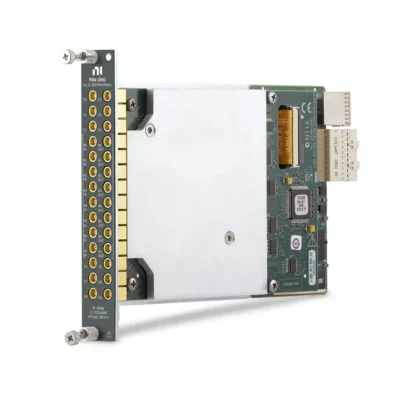
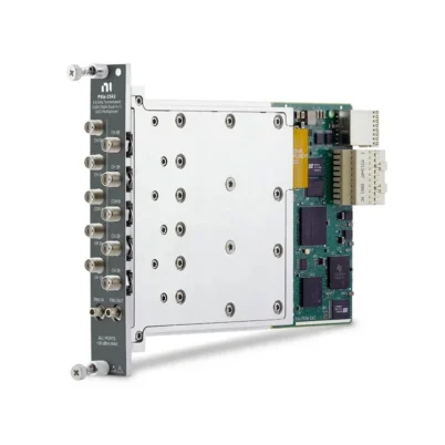
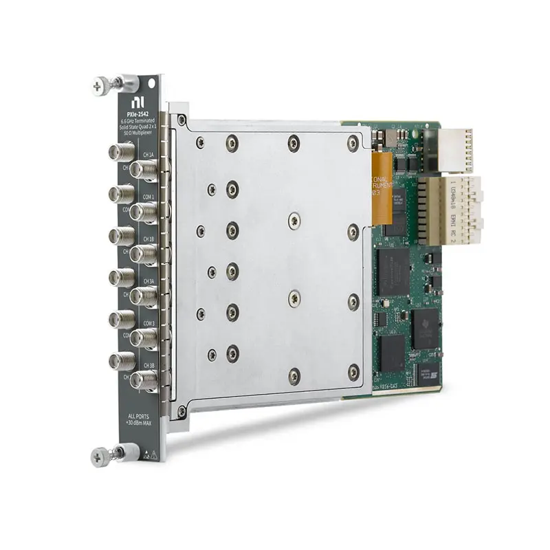
PXIe-2542 6.6 GHz Quad 2×1 RF Switch Module
The PXIe-2542 is a 50 Ω PXI Express solid-state RF switch module with four independently controlled, terminated 2×1 multiplexer banks. It is designed for routing RF signals from 10 MHz to 6.6 GHz in automated validation and high-throughput production test systems.
The module uses high-speed FET switches instead of electromechanical relays, eliminating mechanical contact wear and supporting scan rates up to 8,000 cycles per second. Twelve front-panel SMA connectors provide direct connections to RF instruments and devices under test.
Key Features of the PXIe-2542
- Four independent terminated 2×1 RF multiplexer banks
- Quad SPDT switching configuration
- 10 MHz to 6.6 GHz operating frequency range
- 50 Ω characteristic impedance
- Solid-state FET switching technology
- 8,000-cycle-per-second scan rate
- Maximum 8 V AC switching voltage
- Maximum 1 A AC carry current
- Termination on every channel and common line
- Maximum insertion loss below 6.1 dB at 6.6 GHz
- 12 female SMA front-panel connectors
- Hardware triggering and automated scan-list support
- Single-slot 3U PXI Express module
PXIe-2542 Technical Specifications
| Product Model | PXIe-2542 |
|---|---|
| Part Number | 780587-42 |
| Product Type | PXI Express RF Switch Module |
| Topology | Quad 2×1 terminated multiplexer |
| Relay Configuration | 4 × SPDT |
| Number of Banks | 4 |
| Frequency Range | 10 MHz to 6.6 GHz |
| Characteristic Impedance | 50 Ω |
| Switch Type | Solid-state FET |
| Maximum Switching Voltage | 8 V AC |
| Maximum Carry Current | 1 A AC |
| Scan Rate | 8,000 cycles/s |
| Insertion Loss to 2.4 GHz | Less than 3.7 dB |
| Insertion Loss to 6 GHz | Less than 4.8 dB |
| Insertion Loss to 6.6 GHz | Less than 6.1 dB |
| Front Connectors | 12 × female SMA |
| Bus Interface | PXI Express |
| Module Size | 3U, single slot |
| Operating Temperature | 0°C to 55°C |
Part Number and Configuration
| Part Number | Topology | Frequency Range | Impedance | Connector |
|---|---|---|---|---|
| 780587-42 | Quad 2×1 terminated multiplexer | 10 MHz to 6.6 GHz | 50 Ω | 12 × female SMA |
Quad 2×1 Terminated Multiplexer Architecture
The PXIe-2542 contains four independent 2×1 RF multiplexer banks. Each bank has one common connection and two selectable RF channels, providing the equivalent of four independently controlled SPDT switches.
This architecture allows one module to route four instruments between pairs of devices or route four device signals between two measurement paths. Each bank can be controlled independently through software or included in a hardware-timed scan list.
Terminated RF Signal Paths
Every common connection and channel includes termination. When a path is not selected, its termination helps absorb RF energy instead of leaving the signal line unterminated.
Terminated switching can reduce reflections, improve signal-path consistency and help protect sensitive RF instruments. It is particularly useful when switching signal generators, vector signal analyzers and other equipment that expects a controlled 50 Ω load.
Solid-State FET Switching
The PXIe-2542 uses solid-state FET switches rather than electromechanical relays. Because there are no moving relay contacts, the module does not have a conventional mechanical cycle-life limitation.
Solid-state switching also provides faster operation and greater repeatability in applications requiring frequent route changes. The module supports scanning at up to 8,000 cycles per second, making it suitable for high-volume production testing.
10 MHz to 6.6 GHz RF Coverage
The specified operating frequency range extends from 10 MHz to 6.6 GHz. This coverage supports many cellular, wireless connectivity, navigation, general RF and semiconductor test applications.
The PXIe-2542 is not recommended for signals below its specified 10 MHz lower-frequency limit. Out-of-band operation can reduce signal quality and produce increased harmonics or other unwanted response characteristics.
Insertion Loss Performance
Insertion loss increases with signal frequency. The specified maximum insertion loss is less than 3.7 dB through 2.4 GHz, less than 4.8 dB through 6 GHz and less than 6.1 dB through 6.6 GHz.
Test-system software should compensate for the insertion loss of the switch module, RF cables and adapters when accurate amplitude measurements are required. Characterizing the complete signal path can further improve system-level measurement accuracy.
RF Power and Voltage Considerations
The PXIe-2542 has maximum input voltage, current and continuous RF power limits that must be observed. The safe RF power can depend on frequency, selected path, chassis state and the number of simultaneously active signal paths.
Before connecting an RF source, verify its maximum output power and account for possible gain from external amplifiers. Avoid exceeding the module’s safe continuous RF power curve, even if the applied voltage remains below the separate 8 V switching limit.
Fast Scanning and Hardware Triggering
The module supports scan rates up to 8,000 cycles per second. A predefined route list can be loaded into hardware and executed with reduced host software overhead.
PXI trigger resources allow switching operations to be synchronized with signal generators, vector signal analyzers, power meters and other modular instruments. Hardware synchronization can improve throughput and timing repeatability in automated test sequences.
Typical PXIe-2542 Applications
- RF production testing
- Wireless device validation
- Cellular component testing
- RF semiconductor testing
- Antenna path selection
- Signal generator routing
- Vector signal analyzer routing
- Receiver and transmitter testing
- Multi-device RF test systems
- Automated calibration systems
- High-cycle RF switching
- Research and laboratory RF systems
Software and Driver Support
The PXIe-2542 is controlled using the NI-SWITCH driver. NI-SWITCH supports individual route control, topology configuration, triggering, scan-list execution and integration with automated test applications.
NI Switch Executive can be used to create channel aliases, define routes and manage larger switching systems. The module can also be controlled using NI LabVIEW, LabWindows/CVI, C/C++, C# and supported Python environments.
RF Cables and Connector Requirements
The module provides twelve front-panel female SMA connectors. Use flexible 50 Ω SMA cables and adapters rated for the complete operating frequency range.
Connector condition and torque directly affect insertion loss, return loss and measurement repeatability. Inspect connectors for damaged center pins, contamination or loose interfaces, and use the appropriate SMA torque tool when making connections.
PXI Chassis and System Integration
The PXIe-2542 is a single-slot PXI Express module requiring a compatible PXI Express chassis and controller. Suitable chassis options include the PXIe-1092, PXIe-1085 and other NI PXI Express chassis with an available peripheral slot.
The module can be combined with PXI vector signal analyzers, vector signal transceivers, RF signal generators and power measurement modules to create a compact automated RF test platform.
Installation and Troubleshooting
Module Is Not Detected
Confirm that the PXIe-2542 is installed in a compatible PXI Express peripheral slot. Verify chassis communication and install the required NI-SWITCH driver before checking the module in NI Measurement & Automation Explorer.
Unexpected Signal Loss
Confirm that the intended RF path is selected and include the specified frequency-dependent insertion loss in the system calculation. Inspect cables, adapters and SMA connectors for excessive loss or damage.
Signal Reflections or Poor Return Loss
Use 50 Ω cables and accessories throughout the signal path. Verify connector torque and confirm that the source, load and connected instruments are also designed for 50 Ω operation.
Switch Route Does Not Change
Check the topology and channel names used by the software. Reset the module in NI Measurement & Automation Explorer and test individual routes before running a complete automated scan list.
Measurements Are Inconsistent Between Banks
Characterize each complete RF path, including the PXIe-2542 bank, cables and adapters. Small differences in insertion loss and phase delay can become significant at higher frequencies.
Low-Frequency Signal Quality Is Poor
Verify that the input frequency is at least 10 MHz. The PXIe-2542 is specified for RF operation from 10 MHz to 6.6 GHz and should not be selected for low-frequency or DC switching.
PXIe-2542 Comparison with Similar RF Switch Modules
| Model | Topology | Recommended Selection |
|---|---|---|
| PXIe-2542 | Quad 2×1 terminated multiplexer | Four independent high-speed SPDT RF paths |
| PXIe-2543 | Dual 4×1 terminated multiplexer | Routing four RF channels to each of two common connections |
| PXIe-2544 | 8×1 terminated multiplexer | Routing eight RF channels to one common connection |
| PXI-2542 | Quad 2×1 terminated multiplexer | Similar routing topology for legacy PXI systems |
| PXI-2593 | Configurable RF multiplexer | Applications requiring flexible electromechanical RF routing |
Recommended Related Products
- PXIe-2543 RF Switch Module – provides two terminated 4×1 RF multiplexer banks
- PXIe-2544 RF Switch Module – provides one terminated 8×1 RF multiplexer
- PXI-2593 RF Multiplexer – supports configurable electromechanical RF routing
- PXIe-5841 Vector Signal Transceiver – combines RF signal generation and analysis for wireless testing
- PXIe-1092 PXI Express Chassis – provides a platform for modular RF switching and measurement systems
Additional compatible RF hardware is available in our NI PXI modules category.
How to Select the PXIe-2542
Choose the PXIe-2542 when an RF test system requires four independent SPDT switching paths, terminated ports, solid-state reliability and operation from 10 MHz to 6.6 GHz.
Before purchasing, confirm the topology, frequency range, RF power, insertion loss, isolation, termination requirements, connector count and available PXI Express slot. Choose the PXIe-2543 or PXIe-2544 when a higher fan-in multiplexer topology is required.
Why Choose the PXIe-2542?
The PXIe-2542 combines four terminated RF switching banks, fast solid-state operation and 6.6 GHz bandwidth in a single PXI Express slot. It is optimized for production systems that require frequent switching, controlled impedance and high test throughput.
Frequently Asked Questions
What is the frequency range of the PXIe-2542?
The specified frequency range is 10 MHz to 6.6 GHz.
What switching topology does the PXIe-2542 provide?
It provides four independent, terminated 2×1 multiplexers, equivalent to four SPDT RF switching banks.
Is the PXIe-2542 a 50 Ω switch?
Yes. The module, SMA connections and internal signal paths are designed for 50 Ω RF systems.
Does the PXIe-2542 use electromechanical relays?
No. It uses solid-state FET switches, eliminating mechanical contact wear and enabling faster switching.
What is the maximum scan rate?
The PXIe-2542 supports scan rates up to 8,000 cycles per second.
Are unused channels terminated?
Yes. The module provides termination on its RF channels and common lines to help reduce reflections and protect connected instruments.
Can the PXIe-2542 switch DC signals?
It is not designed for DC signal routing. The specified operating frequency begins at 10 MHz, and operation below that frequency is not recommended.
What is the part number for the PXIe-2542?
The standard NI part number for the PXIe-2542 is 780587-42.
Request a Quote for the PXIe-2542
Contact us for current availability, lead time and project pricing for the PXIe-2542 6.6 GHz Quad 2×1 RF Switch Module. We can also help identify compatible RF cables, PXI chassis, controllers and related switching modules for your test system.
















