








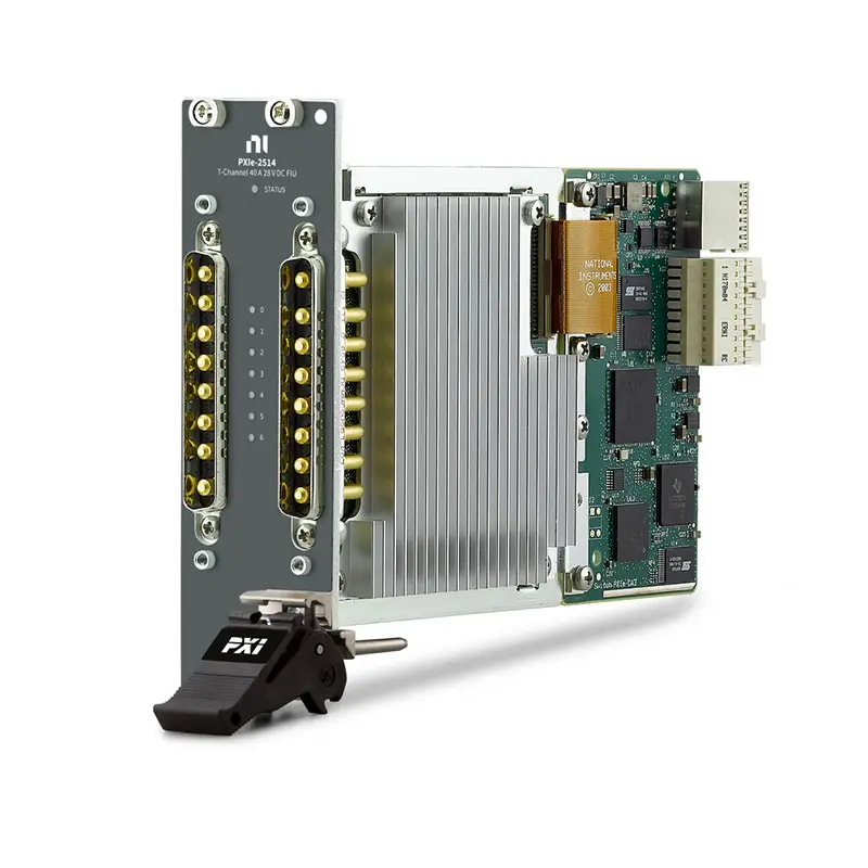
Product Introduction
The NI PXIe-2514 is a PXI Express signal insertion switch module designed for hardware-in-the-loop (HIL) testing, fault insertion, electronic control unit (ECU) validation, automated test equipment, and other applications that require programmable manipulation of signals between a device under test and its normal operating interface.
The PXIe-2514 provides 40 independent signal insertion channels. Each channel can be controlled through electromechanical relays to route, interrupt, or redirect signals as part of an automated test sequence.
This architecture makes the PXIe-2514 particularly useful for fault-insertion systems where engineers need to simulate conditions such as open circuits, shorts, or externally injected signals without manually changing the wiring between the DUT and the test system.
Product Overview
The National Instruments PXIe-2514 is designed primarily for signal insertion and fault-injection applications rather than conventional multiplexing or matrix switching.
In a typical HIL system, the module is installed between the device under test and the simulated or real electrical interface.
A simplified architecture is:
HIL Simulator / System Signal → PXIe-2514 → ECU or DUT
During normal operation, the signal can pass through the switch. During a fault test, the PXIe-2514 can change the electrical path according to the programmed test sequence.
Typical applications include:
- Hardware-in-the-loop testing
- Fault insertion
- ECU validation
- Automotive electronics testing
- Aerospace control-system testing
- Industrial controller validation
- Automated electronic test
- Safety-system validation
- Sensor and actuator interface testing
Key Features
40 Signal Insertion Channels
The PXIe-2514 provides 40 independent signal insertion channels.
The high channel count allows one module to control many DUT signal paths within an automated test system.
Typical signals can include:
- Sensor signals
- Control signals
- Actuator interfaces
- ECU I/O signals
- Industrial control signals
- Low-voltage electrical interfaces
Signal Insertion Architecture
A signal insertion switch is designed to sit directly in the signal path between two devices.
Under normal operating conditions:
Source → PXIe-2514 → DUT
During fault simulation, the original signal path can be interrupted or redirected according to the test configuration.
This architecture allows faults to be introduced automatically without manually disconnecting wires.
Electromechanical Relay Technology
The PXIe-2514 uses electromechanical relay technology.
Electromechanical relays provide true physical switching of the signal path and are commonly used in fault-insertion systems because of their:
- Low contact resistance
- High isolation
- Low leakage
- Bidirectional signal capability
- Ability to switch AC and DC signals within specification
- Physical open-circuit capability
Fault Insertion Capability
One of the primary applications of the PXIe-2514 is automated fault insertion.
A test system can use programmable switching to simulate electrical faults and verify how the DUT responds.
Possible test scenarios include:
- Open-circuit simulation
- Signal interruption
- Signal redirection
- Short-to-ground simulation with appropriate external connections
- Short-to-power simulation with appropriate external connections
- External fault-signal injection
Open-Circuit Simulation
An open circuit is one of the most common electrical faults tested in automotive and embedded control systems.
The PXIe-2514 can disconnect a signal path under software control to reproduce an open-wire condition.
For example:
Sensor → [OPEN] → ECU
The test system can then determine whether the ECU correctly identifies the missing or invalid signal.
Short-to-Ground Fault Testing
When combined with an appropriately designed external fault-insertion network, the PXIe-2514 can be used as part of a system that simulates a DUT signal being shorted to ground.
A simplified configuration is:
DUT Signal → PXIe-2514 → Ground Fault Path
The test system can automatically apply the fault, monitor the DUT response, and then restore normal operation.
Short-to-Power Fault Testing
The PXIe-2514 can also be integrated into systems designed to simulate short-to-power conditions.
A typical architecture is:
DUT Signal → PXIe-2514 → External Fault Voltage
The external voltage source, current limiting, protection circuitry, and switch electrical ratings must all be selected according to the DUT and test requirements.
Automated Fault Sequences
Because the module is software controlled, complex fault sequences can be automated.
For example:
- Operate the DUT normally.
- Open a selected signal channel.
- Monitor the DUT response.
- Restore the normal signal.
- Apply another programmed fault.
- Acquire diagnostic information.
- Compare the response against pass/fail limits.
- Continue to the next test condition.
This is significantly faster and more repeatable than manually rewiring the DUT for every fault condition.
Independent Channel Control
The 40 signal insertion channels can be controlled programmatically, allowing the test system to select the required signal paths for each test step.
This provides flexibility when testing devices with many independent sensor, actuator, and control connections.
PXI Express Platform
The PXIe-2514 is designed for the PXI Express platform.
PXI Express allows the signal insertion module to operate alongside measurement, stimulus, switching, FPGA, CAN/LIN, power, and other instrumentation in the same modular automated test system.
NI-SWITCH Driver Support
The PXIe-2514 can be controlled using the NI-SWITCH instrument driver.
NI-SWITCH provides software functions for:
- Opening switch channels
- Closing switch channels
- Configuring routes
- Automating switching sequences
- Querying switch states
- Integrating switching with automated test software
Technical Specifications
| Parameter | Specification |
|---|---|
| Product Type | PXI Express Signal Insertion Switch Module |
| Model | NI PXIe-2514 |
| Platform | PXI Express |
| Signal Insertion Channels | 40 |
| Switch Technology | Electromechanical Relay |
| Channel Control | Independent, Software Controlled |
| Primary Function | Signal Insertion and Fault Injection |
| Open-Circuit Simulation | Supported |
| Fault Signal Routing | Supported with Appropriate System Configuration |
| Driver | NI-SWITCH |
| Primary Applications | HIL Test, Fault Injection, ECU Validation and Automated Test |
What Is a Signal Insertion Switch?
A signal insertion switch is installed between the normal source of a signal and the receiving device.
Unlike a conventional multiplexer that primarily selects one of several signals, a signal insertion switch is designed to manipulate an existing signal path.
A simplified normal connection is:
Sensor → Signal Insertion Switch → ECU
During testing, the switch can modify the connection:
Sensor → [OPEN] → ECU
or route the ECU input toward an externally configured fault condition.
How Does the PXIe-2514 Work?
The PXIe-2514 places programmable electromechanical relay contacts into multiple DUT signal paths.
During normal operation, the relays maintain the required connection between the DUT and the rest of the test system.
When a fault test is initiated, software changes the relay configuration to interrupt or redirect the selected signal.
The DUT response can then be measured using other PXI instruments.
PXIe-2514 for Hardware-in-the-Loop Testing
The PXIe-2514 is particularly useful in hardware-in-the-loop testing.
A typical HIL system may simulate the environment surrounding an ECU while the real ECU remains connected to the test platform.
A simplified system can include:
Real-Time Model → FPGA / I/O → PXIe-2514 → ECU
The PXIe-2514 provides the switching layer required to introduce controlled electrical faults into selected ECU connections.
ECU Fault Injection Testing
Electronic control units must often respond safely to wiring and sensor failures.
The PXIe-2514 can help automate validation of ECU diagnostic behavior under simulated electrical fault conditions.
Typical test conditions may include:
- Disconnected sensor
- Interrupted actuator connection
- Open harness connection
- Short-to-ground condition
- Short-to-supply condition
- Incorrect external signal
- Intermittent connection
Automotive Electronics Testing
Automotive systems contain large numbers of sensors, actuators, controllers, and communication interfaces.
The PXIe-2514 can be incorporated into automated validation systems for:
- Engine control modules
- Transmission control modules
- Body control modules
- Battery management systems
- Electric vehicle controllers
- Motor control units
- Powertrain controllers
- Electronic steering systems
- Industrial vehicle controllers
Sensor Fault Simulation
The PXIe-2514 can interrupt or redirect compatible sensor signal paths to evaluate DUT behavior when a sensor or wiring connection fails.
For example:
Normal: Sensor → ECU
Fault: Sensor → Open Circuit → ECU
The ECU diagnostic response can then be recorded and evaluated automatically.
Actuator Fault Simulation
Fault insertion is also useful when validating actuator control circuits.
A test system can interrupt an actuator-related signal and verify whether the controller detects the fault and responds correctly.
Applications can include compatible:
- Solenoid circuits
- Relay control signals
- Motor-control interfaces
- Valve-control circuits
- Low-power actuator interfaces
Electrical limits must always be verified before routing actuator signals through the module.
Intermittent Fault Simulation
Some electrical failures are intermittent rather than permanent.
Automated relay control can reproduce repeated connection and disconnection events to evaluate DUT behavior under intermittent wiring conditions.
For example:
Connected → Open → Connected → Open → Connected
The sequence can be coordinated with measurement and diagnostic equipment to determine whether the DUT detects each event correctly.
Fault Injection vs Conventional Switching
| Feature | PXIe-2514 Signal Insertion | Conventional Multiplexer |
|---|---|---|
| Primary Purpose | Fault Insertion / Signal Manipulation | Signal Selection |
| Normal Signal Pass-Through | Designed for Signal Paths | Topology Dependent |
| Open-Circuit Simulation | Yes | Not Primary Function |
| External Fault Routing | Yes, with Appropriate System Design | Topology Dependent |
| Typical Application | HIL / ECU Fault Testing | Measurement Channel Expansion |
PXIe-2514 vs Matrix Switch
A matrix switch and a signal insertion switch solve different routing problems.
| Feature | PXIe-2514 | Matrix Switch |
|---|---|---|
| Architecture | Signal Insertion | Rows × Columns |
| Primary Purpose | Fault Injection | Flexible Instrument Routing |
| Typical DUT | ECU / Controller | Electronic DUT / Semiconductor |
| Open-Wire Simulation | Primary Application | Possible Depending on Topology |
| Instrument Sharing | Secondary | Primary Application |
PXIe-2514 in a Complete HIL System
The PXIe-2514 can be combined with other PXI modules to build a complete automated HIL test platform.
A typical system may include:
- PXI Chassis
- PXI Controller
- PXIe-2514 Signal Insertion Switch
- PXI FPGA / Reconfigurable I/O Modules
- PXI Analog Input Modules
- PXI Analog Output Modules
- PXI CAN / LIN Interfaces
- PXI Digital I/O Modules
- PXI Programmable Power Supplies
- PXI Source Measure Units
Together, these instruments can provide simulation, fault insertion, stimulus, measurement, communication, and automated pass/fail analysis.
Typical HIL Test Architecture
A complete HIL test architecture may be represented as:
Real-Time Simulation → PXI I/O → PXIe-2514 → ECU → Measurement and Diagnostic System
The PXIe-2514 provides the programmable fault-insertion layer between the simulated environment and the ECU.
Using Multiple PXIe-2514 Modules
Applications requiring more than 40 signal insertion channels can use multiple compatible PXIe-2514 modules in a PXI Express system.
For example:
| Number of Modules | Nominal Signal Insertion Channels |
|---|---|
| 1 | 40 |
| 2 | 80 |
| 3 | 120 |
| 4 | 160 |
The actual system configuration depends on chassis capacity, wiring architecture, power requirements, software, and DUT interface design.
Software-Controlled Fault Testing
Software control allows fault conditions to be incorporated directly into automated test sequences.
For example:
Test Step 1: Verify normal DUT operation.
Test Step 2: Introduce an open circuit.
Test Step 3: Verify diagnostic response.
Test Step 4: Restore the connection.
Test Step 5: Apply the next fault condition.
Test Step 6: Record pass/fail results.
This provides repeatable fault testing across multiple DUTs and production or validation cycles.
NI-SWITCH Software Integration
The PXIe-2514 can be integrated into automated test applications using NI-SWITCH.
The driver allows software to control switch states and coordinate fault insertion with other measurement operations.
Applications can combine switching with:
- Voltage measurements
- Current measurements
- Waveform acquisition
- Digital I/O
- CAN/LIN communication
- Real-time simulation
- Automated diagnostic testing
LabVIEW Integration
LabVIEW applications can incorporate the PXIe-2514 into custom automated test and HIL software.
A LabVIEW-based test system can:
- Configure signal routes
- Apply fault conditions
- Control test sequences
- Acquire DUT measurements
- Monitor diagnostic responses
- Record test results
- Generate pass/fail decisions
TestStand Integration
The PXIe-2514 can also be incorporated into TestStand-based automated validation systems.
Individual test steps can control switching conditions, apply faults, perform measurements, verify DUT behavior, and automatically record results.
This approach is particularly useful for standardized ECU validation and production test procedures.
Relay Life Considerations
Because the PXIe-2514 uses electromechanical relays, relay lifetime should be considered when designing high-volume automated test systems.
Relay life depends on factors including:
- Number of switching operations
- Signal voltage
- Signal current
- Load characteristics
- Switching frequency
- Environmental conditions
High-current or highly reactive loads can reduce relay life compared with low-level signal switching.
Electrical Safety Considerations
Before connecting a DUT to the PXIe-2514, engineers should verify the complete electrical specifications of the module and accessory configuration.
Important considerations include:
- Maximum switching voltage
- Maximum switching current
- Maximum switching power
- Maximum carry current
- Channel-to-channel voltage
- Channel-to-ground voltage
- Load type
- External fault-source voltage
- External current limiting
- Protection circuitry
A fault-insertion system should never be designed by considering only one voltage or current specification independently.
How to Choose a Signal Insertion Switch
Before selecting the PXIe-2514, evaluate:
- Required number of fault-insertion channels
- DUT signal voltage
- DUT signal current
- Required fault types
- Open-circuit requirements
- Short-to-ground requirements
- Short-to-power requirements
- External fault bus architecture
- Relay switching speed
- Relay lifetime
- PXI Express chassis compatibility
- Connector and cabling requirements
- NI-SWITCH software compatibility
Industries
- Automotive Electronics
- Electric Vehicle Testing
- Hardware-in-the-Loop Testing
- Aerospace and Defense
- Industrial Automation
- Transportation Electronics
- Electronic Manufacturing
- Embedded Systems
- Research and Development
Applications
Hardware-in-the-Loop Testing
The PXIe-2514 provides programmable signal interruption and fault insertion for HIL systems used to validate real electronic controllers against simulated operating conditions.
ECU Fault Injection
The module can help automate open-circuit and externally configured electrical fault tests on ECU sensor, actuator, and control connections.
Automotive Validation
The PXIe-2514 can be integrated into automated validation systems for powertrain, body, battery, motor-control, and other automotive electronic controllers.
Sensor Fault Simulation
Signal paths can be interrupted or redirected to reproduce compatible sensor and wiring failures during automated testing.
Safety-System Validation
Controlled fault insertion allows engineers to verify how electronic systems respond when expected electrical connections fail.
Automated Functional Testing
Software-controlled switching enables repeatable fault conditions to be incorporated into automated electronic test sequences.
Recommended Related Products
| NI PXIe-2514 | 40-channel PXI Express signal insertion switch designed for automated fault injection and HIL testing. |
| NI PXI/PXIe Switching Modules | Programmable PXI switching solutions for signal insertion, multiplexing, matrix routing, fault injection, and automated test. |
| NI PXI-2529 | 128-crosspoint 2-wire matrix switch for flexible routing between measurement instruments and DUT signals. |
| NI PXIe-2532B | High-density PXI Express matrix switch for automated test systems requiring a large number of programmable routing crosspoints. |
| NI PXI Modules | PXI and PXI Express instrumentation for switching, data acquisition, FPGA processing, source measurement, RF testing, and automated validation. |
Why Choose NI PXIe-2514?
- 40 signal insertion channels
- PXI Express platform
- Electromechanical relay architecture
- Programmable signal interruption
- Open-circuit fault simulation
- External fault signal routing capability
- Independent software-controlled switching
- Designed for HIL test systems
- Suitable for ECU fault injection
- Suitable for automotive validation
- Suitable for sensor and actuator fault testing
- NI-SWITCH software support
- Integration with LabVIEW and automated test software
- Scalable using multiple modules
Frequently Asked Questions
What is the NI PXIe-2514?
The NI PXIe-2514 is a 40-channel PXI Express signal insertion switch module designed primarily for automated fault insertion, HIL testing, ECU validation, and electronic system testing.
How many channels does the PXIe-2514 have?
The PXIe-2514 provides 40 signal insertion channels.
What is a signal insertion switch?
A signal insertion switch is installed in an existing electrical signal path and allows software to maintain, interrupt, or redirect that path. It is commonly used for automated fault-injection testing.
Can the PXIe-2514 simulate an open circuit?
Yes. Opening the appropriate relay path allows the PXIe-2514 to reproduce an open-circuit or disconnected-wire condition on a compatible DUT signal.
Can the PXIe-2514 simulate a short to ground?
The PXIe-2514 can be incorporated into a properly designed fault-insertion system that routes a selected signal toward a ground fault path. The complete electrical configuration must remain within the module and system ratings.
Can the PXIe-2514 simulate a short to power?
Yes, as part of an appropriately designed external fault-insertion architecture. External voltage sources, protection, current limiting, and all switch ratings must be considered.
Can the PXIe-2514 be used for HIL testing?
Yes. Hardware-in-the-loop fault insertion is one of the primary applications for the PXIe-2514.
Can the PXIe-2514 be used for ECU testing?
Yes. The module is particularly useful for ECU validation where automated tests must reproduce wiring, sensor, and other electrical fault conditions.
Does the PXIe-2514 use solid-state or electromechanical relays?
The PXIe-2514 uses electromechanical relays.
What driver is used with the PXIe-2514?
The PXIe-2514 is controlled using the NI-SWITCH driver.
Can I use multiple PXIe-2514 modules?
Yes. Multiple modules can be installed in a compatible PXI Express system when more than 40 signal insertion channels are required.
Can the PXIe-2514 be used with LabVIEW?
Yes. It can be incorporated into LabVIEW-based automated test and HIL applications through compatible NI driver software.
Can the PXIe-2514 be used with TestStand?
Yes. Switching and fault-insertion operations can be incorporated into TestStand-based automated test sequences through the appropriate software architecture.
What is the difference between the PXIe-2514 and a matrix switch?
The PXIe-2514 is optimized for signal insertion and fault simulation in existing DUT signal paths. A matrix switch is primarily designed to create flexible connections between multiple instrument rows and DUT columns.
Is the PXIe-2514 suitable for automotive testing?
Yes. Typical applications include automotive ECU validation, HIL testing, sensor fault simulation, actuator interface testing, and electric vehicle controller validation.
What should I check before purchasing a PXIe-2514?
Before purchasing the PXIe-2514, verify the required channel count, DUT voltage and current levels, fault types, external fault-bus requirements, switching power, relay life, connector and cabling requirements, PXI Express chassis compatibility, NI-SWITCH compatibility, and the exact NI ordering configuration.
Conclusion
The NI PXIe-2514 40-Channel PXI Express Signal Insertion Switch Module provides programmable signal interruption and routing for hardware-in-the-loop testing, fault injection, ECU validation, and automated electronic test systems. Its 40 independent signal insertion channels and electromechanical relay architecture allow engineers to automate open-circuit and externally configured fault conditions while integrating the switching system with other PXI measurement, simulation, communication, and stimulus hardware.















