







Product Introduction
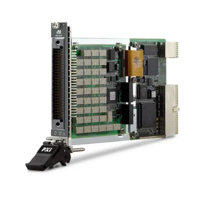
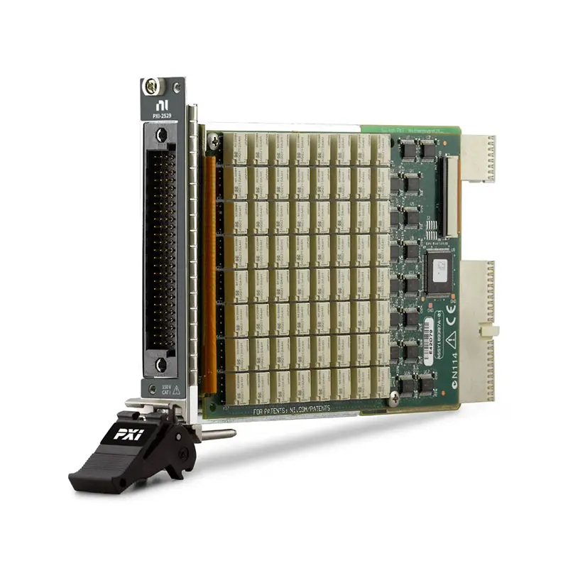
The NI PXI-2529 is a high-density, 128-crosspoint, 2-wire PXI matrix switch module designed for automated test systems requiring flexible routing of multiple signals between measurement instruments and devices under test (DUTs).
The PXI-2529 uses electromechanical relays and can be configured as either a 4×32 or 8×16 2-wire matrix depending on the selected front-mount terminal block. This architecture makes the module suitable for automated electronic test, semiconductor validation, functional test, data acquisition signal routing, and high-channel-count measurement systems.
The module supports switching voltages up to 150 VDC and switching currents up to 1 A DC. Its electromechanical relay architecture also provides low thermal offset characteristics, making the PXI-2529 useful for routing both higher-power signals and precision low-level measurements.
Product Overview
The National Instruments PXI-2529 provides 128 possible switching crosspoints in a compact PXI module.
A matrix switch allows multiple rows and columns to be interconnected under software control. Unlike a simple multiplexer that typically routes many inputs to one output, a matrix architecture provides substantially greater routing flexibility.
Depending on the selected terminal block, the PXI-2529 can operate as:
- 4×32 2-wire matrix
- 8×16 2-wire matrix
Typical applications include:
- Automated test equipment
- Electronic device validation
- Semiconductor testing
- Functional production test
- Signal routing
- Data acquisition systems
- DMM measurement routing
- Source Measure Unit routing
- Power supply routing
- Multi-DUT testing
Key Features
128 Switching Crosspoints
The PXI-2529 provides 128 matrix crosspoints.
A crosspoint represents a potential electrical connection between a row and a column in the matrix.
For example:
4 Rows × 32 Columns = 128 Crosspoints
or:
8 Rows × 16 Columns = 128 Crosspoints
This high-density architecture allows a large number of DUT signals to share a smaller number of measurement instruments.
2-Wire Matrix Architecture
The PXI-2529 is a 2-wire matrix switch.
Each matrix connection switches two conductors together, making the module particularly suitable for differential and two-wire measurement architectures.
Typical two-wire applications include:
- Precision voltage measurement
- Resistance measurement
- Current measurement architectures
- Source Measure Unit routing
- DMM routing
- Two-wire DUT interfaces
4×32 Matrix Configuration
The PXI-2529 can be configured as a 4×32 2-wire matrix using an appropriate terminal block.
This topology provides four instrument-side rows and 32 DUT-side columns.
A typical architecture is:
4 Measurement / Source Paths ↔ 32 DUT Signal Paths
This configuration is particularly useful when a relatively small number of instruments must be routed to a large number of DUT connections.
8×16 Matrix Configuration
The PXI-2529 can also be configured as an 8×16 2-wire matrix.
This provides additional row connections while reducing the number of available columns.
A typical architecture is:
8 Measurement / Source Paths ↔ 16 DUT Signal Paths
The 8×16 topology can be useful when a test system contains more instruments or source channels that need access to the DUT.
Electromechanical Relay Technology
The PXI-2529 uses electromechanical relays for signal switching.
Electromechanical relays provide several advantages for general-purpose automated test:
- Low contact resistance
- Low leakage
- Good isolation
- Ability to route DC signals
- Ability to route AC signals within specification
- Low thermal offset
- Support for relatively high switching voltage and current
150 V Maximum Switching Voltage
The PXI-2529 supports a maximum switching voltage of up to 150 VDC within its specified operating limits.
This allows the module to route substantially higher voltages than many low-voltage semiconductor-based digital switching solutions.
The 150 V rating is a critical electrical and safety limit and should not be exceeded.
1 A Maximum DC Switching Current
The PXI-2529 supports a maximum DC switching current of 1 A.
The actual allowable switching conditions depend on voltage, current, power, topology, terminal block, environmental conditions, and other specifications.
Users should therefore evaluate the complete NI switching specifications rather than considering voltage and current ratings independently.
120 Cycles/s Scan Rate
NI specifies a scan rate of up to 120 cycles per second for the PXI-2529.
Automated scanning allows the test system to sequentially connect instruments to multiple DUT points without manual rewiring.
A typical sequence is:
Connect DUT 1 → Measure → Disconnect → Connect DUT 2 → Measure → Repeat
Low Thermal Offset
The electromechanical relay architecture of the PXI-2529 is designed to provide low thermal offset for accurate low-level measurements.
This is particularly important when the matrix is used with precision measurement instruments such as:
- Digital multimeters
- Source Measure Units
- Precision voltage measurement instruments
- Low-level data acquisition systems
Onboard Relay Counting
The PXI-2529 provides onboard relay counting to help monitor relay usage.
Because electromechanical relays have a finite mechanical life, relay-count information can be valuable for preventive maintenance and test-system reliability management.
Maintenance software can use relay-count information to identify heavily used signal paths before relay wear begins affecting production testing.
Hardware Triggering
The PXI-2529 supports hardware-triggered switching for deterministic operation in automated test systems.
Hardware triggering can coordinate switch operations with:
- PXI digital multimeters
- Source Measure Units
- Data acquisition modules
- Digitizers
- Power supplies
- Other PXI instrumentation
This can improve test throughput compared with test sequences that depend entirely on software commands.
PXI Hybrid Compatibility
The PXI-2529 uses a PXI Hybrid bus connector.
This allows the module to be integrated into compatible PXI chassis and automated test systems alongside other PXI instrumentation.
Technical Specifications
| Parameter | Specification |
|---|---|
| Product Type | PXI Matrix Switch Module |
| Model | NI PXI-2529 |
| Part Number | 778739-01 |
| Matrix Type | 2-Wire |
| Crosspoints | 128 |
| Matrix Configurations | 4×32 or 8×16 |
| Relay Type | Electromechanical |
| Maximum Switching Voltage DC | 150 V |
| Maximum Switching Current DC | 1 A |
| Maximum Scan Rate | 120 Cycles/s |
| Relay Counting | Supported |
| Hardware Triggering | Supported |
| Bus Connector | PXI Hybrid |
| Terminal Block Interface | HDI 100-Pin |
| Driver | NI-SWITCH |
| Primary Applications | Automated Signal Routing, Electronic Test, Semiconductor Test, DMM/SMU Routing and Multi-DUT Test |
How Does the PXI-2529 Work?
The PXI-2529 contains an array of electromechanical relays arranged as a programmable matrix.
Software determines which row-to-column crosspoints are closed.
For example, in a 4×32 configuration:
Instrument Row 0 → DUT Column 5
Instrument Row 1 → DUT Column 12
Instrument Row 2 → DUT Column 20
Instrument Row 3 → DUT Column 28
The matrix can then be reconfigured automatically for the next measurement sequence.
What Is a Matrix Switch?
A matrix switch provides programmable connections between multiple rows and multiple columns.
A simplified matrix can be represented as:
Rows = Measurement Instruments / Sources
Columns = DUT Test Points
The intersections between rows and columns are called crosspoints.
Closing a crosspoint connects the corresponding row to the corresponding column.
Matrix Switch vs Multiplexer
| Feature | Matrix Switch | Multiplexer |
|---|---|---|
| Routing Architecture | Multiple Rows × Multiple Columns | Many Channels to One/Few Common Paths |
| Routing Flexibility | Very High | Moderate |
| Multiple Instrument Routing | Excellent | More Limited |
| Typical Application | Complex Automated Test | Sequential Data Acquisition |
| Example | PXI-2529 | PXI/PXIe Multiplexer Module |
PXI-2529 for DMM Signal Routing
One common application for the PXI-2529 is routing multiple DUT test points to a PXI digital multimeter.
A typical architecture is:
Multiple DUT Test Points → PXI-2529 → PXI Digital Multimeter
The switch automatically selects the required DUT signal while the DMM performs the measurement.
This architecture can dramatically increase the effective channel count of a precision DMM without requiring one measurement instrument for every test point.
PXI-2529 for Source Measure Unit Routing
The PXI-2529 can also route compatible voltage and current signals between Source Measure Units and multiple DUT connections.
A simplified architecture is:
PXI SMU → PXI-2529 → Multiple DUTs
This allows a smaller number of SMUs to be shared across multiple test points when simultaneous connections are not required.
All applied voltages, currents, power levels, and isolation requirements must remain within the PXI-2529 specifications.
Multi-DUT Testing
The high-density matrix architecture makes the PXI-2529 useful for multi-DUT automated testing.
For example:
DMM / SMU / Power Supply → PXI-2529 → DUT 1 / DUT 2 / DUT 3 / DUT 4
Test software can dynamically reconfigure the matrix so that instruments are shared between DUTs.
This approach can reduce:
- Instrument count
- PXI chassis slot requirements
- System cost
- External cabling complexity
- Manual connection changes
Semiconductor Test Applications
Semiconductor characterization and production test systems often require multiple precision instruments to connect to many DUT pins.
The PXI-2529 can provide programmable routing between compatible DUT connections and instruments such as:
- Source Measure Units
- Digital multimeters
- Power supplies
- Data acquisition modules
- Electronic loads
A matrix architecture allows the same instruments to be reused across multiple DUT connections.
Electronic Functional Testing
The PXI-2529 can be incorporated into functional test systems for electronic assemblies, modules, and printed circuit boards.
Typical measurements may include:
- DC voltage
- Resistance
- Continuity
- Current
- Power rail verification
- Component validation
Low-Level Measurement Applications
Switches can introduce unwanted thermoelectric voltages when different conductive materials and temperature gradients are present.
The low thermal offset characteristics of the PXI-2529 electromechanical relays make the module suitable for precision low-voltage measurements when the complete measurement system is designed appropriately.
Typical applications include:
- Precision DMM measurements
- Low-voltage sensor measurements
- Resistance characterization
- Semiconductor characterization
- Precision automated test
High-Voltage Signal Routing
The PXI-2529 can switch signals up to 150 V within its specified operating conditions.
This makes it suitable for automated systems requiring signal levels beyond typical low-voltage DAQ applications.
However, 150 V is a critical maximum rating. The module should not be used to route signals exceeding its specified voltage limit.
Relay Life and Relay Counting
Electromechanical relays have a finite operating life that depends strongly on switching conditions.
Factors affecting relay life include:
- Switching voltage
- Switching current
- Load type
- Switching frequency
- Electrical arcing
- Environmental conditions
The PXI-2529 onboard relay-counting capability can help maintenance teams monitor relay usage and plan preventative replacement.
PXI-2529 Terminal Blocks
The PXI-2529 uses front-mount terminal blocks to define its matrix topology and external signal connections.
NI provides several terminal block options for the NI 2529 family.
TB-2634
The NI TB-2634, part number 778840-01, configures the PXI-2529 as a 4×32 2-wire matrix without column protection resistors.
This configuration is useful when maximum routing flexibility and direct signal paths are required within the specified electrical limits.
TB-2635
The NI TB-2635 configures the NI 2529 for a 4×32 2-wire matrix with column protection.
The protection architecture can be useful in measurement systems where additional current-limiting protection is required for instrument-side connections.
TB-2636
The NI TB-2636 configures the NI 2529 as an 8×16 2-wire matrix.
This topology provides twice as many matrix rows as the 4×32 configuration, making it suitable for systems that need more independent instrument paths.
4×32 vs 8×16 Configuration
| Feature | 4×32 | 8×16 |
|---|---|---|
| Rows | 4 | 8 |
| Columns | 32 | 16 |
| Crosspoints | 128 | 128 |
| Best For | More DUT Connections | More Instrument Connections |
| Typical Architecture | Few Instruments → Many DUT Points | More Instruments → Fewer DUT Points |
How to Choose the Correct Matrix Topology
Choosing between 4×32 and 8×16 depends primarily on the number of instrument paths and DUT connections required.
Choose a 4×32 topology when:
- You have relatively few measurement instruments
- You need to connect to many DUT test points
- Four matrix rows are sufficient
Choose an 8×16 topology when:
- You need more independent instrument paths
- Sixteen DUT-side columns are sufficient
- The system requires greater instrument-side routing flexibility
PXI-2529 vs PXIe-2529
NI offers both PXI and PXI Express versions of the 2529 matrix switch architecture.
| Feature | PXI-2529 | PXIe-2529 |
|---|---|---|
| Crosspoints | 128 | 128 |
| Matrix Type | 2-Wire | 2-Wire |
| Configurations | 4×32 / 8×16 | 4×32 / 8×16 |
| Maximum DC Switching Voltage | 150 V | 150 V |
| Maximum DC Switching Current | 1 A | 1 A |
| Bus Interface | PXI Hybrid | PXI Express |
| Part Number | 778739-01 | 780587-29 |
PXI-2529 vs PXI-2532B
The PXI-2529 and PXI-2532B are both matrix switching solutions, but they are optimized for different routing requirements.
| Feature | PXI-2529 | PXI-2532B |
|---|---|---|
| Crosspoints | 128 | Higher-Density Architecture |
| Primary Architecture | 2-Wire Matrix | High-Density Matrix |
| Maximum Voltage | Up to 150 V | Topology / Configuration Dependent |
| Relay Technology | Electromechanical | Electromechanical |
| Best Application | General 2-Wire Precision Routing | Higher-Channel-Count Routing |
PXI-2529 in a Complete PXI System
The PXI-2529 can provide programmable signal routing within a complete PXI system.
A typical automated test system may include:
- PXI Chassis
- PXI Controller
- PXI-2529 Matrix Switch
- PXI Digital Multimeter
- PXI Source Measure Unit
- PXI Programmable Power Supply
- PXI Data Acquisition Module
- PXI Modules
The matrix switch provides the routing layer between the measurement instruments and DUT test points.
PXI-2529 with a Digital Multimeter
Combining the PXI-2529 with a PXI DMM creates a scalable multichannel precision measurement system.
A simplified configuration is:
32 DUT Test Points → PXI-2529 → PXI DMM
The matrix sequentially connects the required DUT points to the DMM, allowing one precision measurement instrument to serve many test points.
PXI-2529 with Source Measure Units
A PXI-2529 can route compatible SMU signals to different DUT pins or devices.
For example:
SMU 1 → Matrix Row 0
SMU 2 → Matrix Row 1
DUT Pins → Matrix Columns
Software then determines which SMU is connected to which DUT test point.
This architecture can reduce the number of SMUs required for sequential characterization applications.
Automated Test Sequence
A typical PXI-2529 automated measurement sequence can be:
- Open existing matrix connections.
- Select the required row and column.
- Close the required crosspoint relay.
- Wait for relay settling.
- Trigger the measurement instrument.
- Acquire the measurement.
- Store the result.
- Open the connection.
- Select the next DUT test point.
- Repeat the sequence.
NI-SWITCH Software Support
The PXI-2529 is supported by the NI-SWITCH instrument driver.
NI-SWITCH provides programmatic control of switch routing and scanning operations.
Software can be used to:
- Connect matrix channels
- Disconnect matrix channels
- Configure scan lists
- Control triggering
- Monitor relay usage
- Automate switching sequences
NI Switch Executive Integration
The PXI-2529 can also be incorporated into systems using NI Switch Executive.
Switch Executive allows test developers to work with logical route names rather than manually managing every individual relay connection.
This can simplify complex automated switching systems containing multiple PXI switch modules.
How to Choose a PXI Matrix Switch
Before selecting the PXI-2529, evaluate:
- Required number of matrix rows
- Required number of matrix columns
- Number of crosspoints
- 1-wire or 2-wire signal requirements
- Maximum signal voltage
- Maximum switching current
- Maximum switching power
- Required bandwidth
- Thermal offset requirements
- Relay life requirements
- Scanning speed
- Required terminal block
- PXI chassis compatibility
- Software and driver compatibility
Industries
- Automated Test Equipment
- Semiconductor Test
- Electronic Manufacturing
- Automotive Electronics
- Aerospace and Defense
- Industrial Electronics
- Power Electronics
- Research and Development
- Laboratory Measurement
Applications
Automated Signal Routing
The PXI-2529 can automatically route multiple DUT signals to shared measurement and stimulus instruments.
Semiconductor Characterization
Matrix switching allows compatible SMUs, DMMs, and other precision instruments to be shared across multiple semiconductor DUT connections.
Multi-DUT Production Test
The 128-crosspoint architecture can reduce instrument count by allowing measurement resources to be dynamically shared between DUTs.
DMM Measurement Systems
The PXI-2529 can expand the effective channel count of a PXI digital multimeter by sequentially routing multiple measurement points to the instrument.
Source Measure Unit Routing
Compatible SMU source and measurement signals can be routed to multiple DUT connections under automated software control.
Electronic Functional Test
The PXI-2529 can provide flexible signal routing for PCB, electronic assembly, module, and subsystem functional test systems.
Recommended Related Products
| NI PXI-2529 | 128-crosspoint 2-wire PXI matrix switch configurable as 4×32 or 8×16 for automated signal routing. |
| NI PXIe-2529 | PXI Express version of the 128-crosspoint 2529 matrix switch architecture. |
| NI TB-2634 | Terminal block for configuring the NI 2529 as a 4×32 2-wire matrix without column protection resistors. |
| NI TB-2635 | Terminal block for configuring the NI 2529 as a protected 4×32 2-wire matrix. |
| NI TB-2636 | Terminal block for configuring the NI 2529 as an 8×16 2-wire matrix. |
| NI PXIe-2532B | High-density PXI Express matrix switch for automated test systems requiring additional routing density and topology options. |
| NI PXI Modules | PXI instrumentation for switching, data acquisition, source measurement, waveform acquisition, RF test, and automated measurement systems. |
Why Choose NI PXI-2529?
- 128 switching crosspoints
- 2-wire matrix architecture
- Configurable 4×32 topology
- Configurable 8×16 topology
- Electromechanical relays
- Up to 150 VDC switching
- Up to 1 A DC switching current
- Up to 120 cycles/s scan rate
- Low thermal offset relay architecture
- Onboard relay counting
- Hardware-triggered operation
- PXI Hybrid interface
- NI-SWITCH driver support
- Suitable for DMM and SMU routing
- Suitable for multi-DUT automated test
- Suitable for semiconductor characterization
Frequently Asked Questions
What is the NI PXI-2529?
The NI PXI-2529 is a 128-crosspoint, 2-wire PXI matrix switch module designed for programmable signal routing in automated test and measurement systems.
What is the part number of the PXI-2529?
The NI ordering part number for the PXI-2529 is 778739-01.
How many crosspoints does the PXI-2529 have?
The PXI-2529 provides 128 switching crosspoints.
What matrix configurations does the PXI-2529 support?
The module can be configured as either a 4×32 or 8×16 2-wire matrix using the appropriate terminal block.
Is the PXI-2529 a 2-wire matrix?
Yes. The PXI-2529 is designed as a 2-wire matrix switch.
What type of relays does the PXI-2529 use?
The PXI-2529 uses electromechanical relays.
What is the maximum switching voltage of the PXI-2529?
NI specifies a maximum DC switching voltage of 150 V. This rating should not be exceeded.
What is the maximum switching current of the PXI-2529?
The maximum DC switching current is 1 A, subject to the complete electrical and switching-power specifications.
What is the scan rate of the PXI-2529?
NI lists a maximum scan rate of 120 cycles per second.
Can the PXI-2529 be used with a digital multimeter?
Yes. DMM signal routing is a common matrix-switch application. The PXI-2529 can connect multiple compatible DUT measurement points to a shared PXI DMM.
Can the PXI-2529 be used with an SMU?
Yes, provided the voltage, current, power, and isolation requirements remain within the PXI-2529 specifications. The matrix can route compatible SMU signals to different DUT connections.
Can the PXI-2529 switch more than 150 V?
No. The PXI-2529 should not be operated above its specified 150 V maximum voltage rating. Applications requiring higher voltages should use switching hardware specifically rated for the required voltage.
What is the difference between a 4×32 and 8×16 PXI-2529 configuration?
Both configurations provide 128 crosspoints. The 4×32 configuration provides fewer rows and more columns, while the 8×16 configuration provides more rows and fewer columns. The correct topology depends on the number of instruments and DUT connections required.
What terminal block is used for a 4×32 PXI-2529 configuration?
The TB-2634 is one of the available terminal blocks for configuring the NI 2529 as a 4×32 2-wire matrix without column protection resistors. Other terminal-block configurations are available depending on the required protection and topology.
What terminal block is used for an 8×16 PXI-2529 configuration?
The TB-2636 is used to configure the NI 2529 for an 8×16 2-wire matrix topology.
Does the PXI-2529 support relay counting?
Yes. The PXI-2529 includes onboard relay counting to help monitor electromechanical relay usage.
Does the PXI-2529 support hardware triggering?
Yes. Hardware-triggered operation can be used for deterministic switching and improved automated test throughput.
What software driver does the PXI-2529 use?
The PXI-2529 is supported by the NI-SWITCH driver and can also be integrated into switching systems using NI Switch Executive.
What is the difference between PXI-2529 and PXIe-2529?
Both provide 128-crosspoint, 2-wire matrix switching with 4×32 or 8×16 configurations. The primary platform difference is that the PXI-2529 uses a PXI Hybrid interface, while the PXIe-2529 uses PXI Express. Their ordering part numbers are also different.
What should I check before purchasing a PXI-2529?
Before purchasing the PXI-2529, verify the required matrix topology, number of rows and columns, voltage, current, switching power, bandwidth, thermal offset, relay life, terminal block, connector requirements, PXI chassis compatibility, NI-SWITCH support, and exact NI ordering part number.
Conclusion
The NI PXI-2529 128-Crosspoint 2-Wire PXI Matrix Switch Module provides flexible high-density signal routing for automated test systems. Its configurable 4×32 or 8×16 topology, electromechanical relays, 150 VDC maximum switching voltage, 1 A maximum DC switching current, low thermal offset, onboard relay counting, and hardware-triggered operation make it well suited for DMM routing, SMU routing, semiconductor characterization, electronic functional test, multi-DUT production test, and other automated measurement applications.
















