




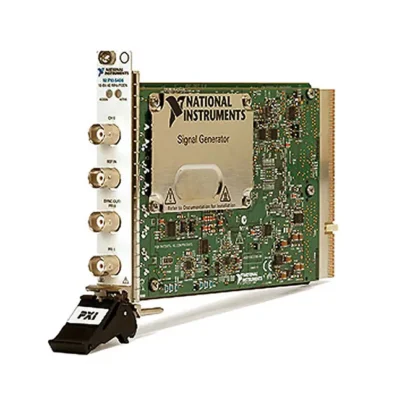
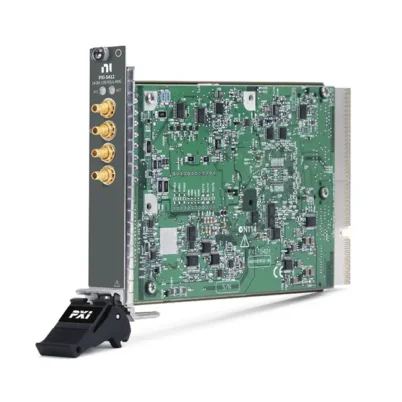
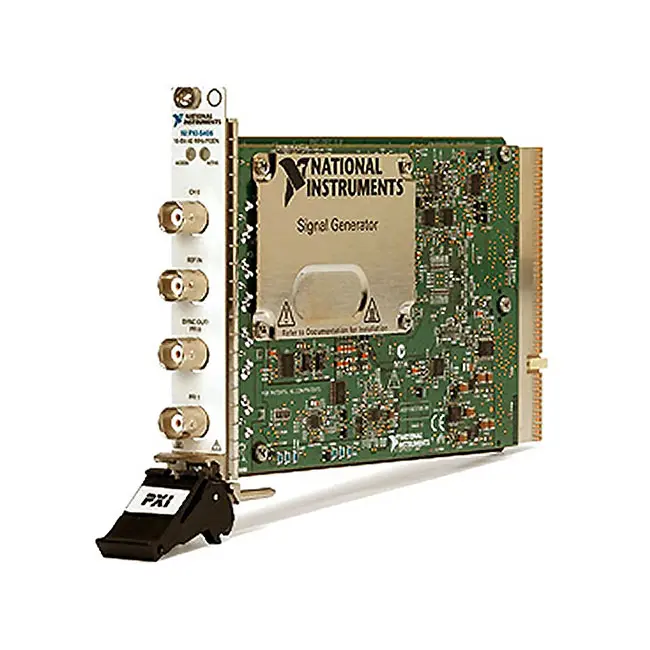
PXI-5402 20 MHz 14-Bit PXI Waveform Generator
The NI PXI-5402 is a single-channel PXI waveform and function generator designed for automated test, electronic-device validation, stimulus generation and laboratory measurement systems. It combines 14-bit output resolution, a 100 MS/s sampling rate and signal frequencies up to 20 MHz in a compact one-slot PXI module.
The PXI-5402 generates sine, square, triangle, ramp, noise, DC and user-defined waveforms. Digital interpolation increases the effective update rate to as much as 400 MS/s for supported waveform types, while programmable amplitude, DC offset, phase and output impedance provide flexible stimulus configuration.
Key Features of the PXI-5402
- Single analog waveform output channel
- 14-bit digital-to-analog converter resolution
- 100 MS/s hardware sampling rate
- Up to 400 MS/s effective update rate with interpolation
- 20 MHz sine-wave and square-wave output
- 20 MHz maximum user-defined waveform frequency
- 1 MHz triangle and ramp output
- Up to 10 Vpk-pk output into a 50 Ω load
- Up to 20 Vpk-pk output into a high-impedance load
- Software-selectable 50 Ω or 75 Ω output impedance
- Sine, square, triangle, ramp, DC and noise generation
- 16,384-sample user-defined waveform size
- 32 MB onboard frequency-list memory
- Frequency-list mode with up to 58,235 steps
- External and PXI backplane triggering
- External-reference and PXI_CLK10 synchronization
- NI-TClk multi-module synchronization support
- Onboard self-calibration capability
- NI-FGEN software support
- Compact 3U, one-slot PXI form factor
PXI-5402 Technical Specifications
| Product Model | PXI-5402 |
|---|---|
| Part Number | 779655-01 |
| Product Type | PXI waveform and function generator |
| Number of Output Channels | 1 |
| DAC Resolution | 14 bits |
| Hardware Sampling Rate | 100 MS/s |
| Maximum Effective Update Rate | 400 MS/s with supported digital interpolation |
| Sine-Wave Frequency | Up to 20 MHz |
| Square-Wave Frequency | Up to 20 MHz |
| Triangle-Wave Frequency | Up to 1 MHz |
| Ramp-Wave Frequency | Up to 1 MHz |
| User-Defined Waveform Frequency | Up to 20 MHz |
| User-Defined Waveform Size | 16,384 samples |
| Frequency Resolution | 0.355 µHz |
| Amplitude Range, 50 Ω Load | 5.64 mVpk-pk to 10 Vpk-pk |
| Amplitude Range, High-Impedance Load | 11.28 mVpk-pk to 20 Vpk-pk |
| Maximum Output Voltage | ±5 V, AC peak plus DC |
| Output Impedance | Software-selectable 50 Ω or 75 Ω |
| Phase Adjustment | −180° to +180° |
| Digital Interpolation | 1×, 2× or 4× |
| Analog Filter | Software-selectable seven-pole elliptical filter |
| Sample Clock Accuracy | ±25 ppm |
| Frequency-List Steps | 1 to 58,235 steps |
| Frequency-List Step Duration | 1 ms to 21 seconds |
| Trigger Modes | Single, continuous, stepped and burst |
| Reference Clock Range | 5 MHz to 20 MHz in 1 MHz increments |
| Calibration Interval | 2 years |
| Warm-Up Time | 15 minutes |
| Total Power Consumption | 17.6 W |
| Analog Output Connector | BNC female |
| Reference Input Connector | BNC female |
| Trigger and Synchronization Connectors | SYNC OUT/PFI 0 and PFI 1 BNC connectors |
| Module Format | 3U, one-slot PXI/cPCI module |
| Dimensions | 21.6 × 2.0 × 13.0 cm |
| Weight | 351 g |
| Software Driver | NI-FGEN |
PXI-5402 Part Number and Connection Accessories
| Item | Part Number or Type | Description |
|---|---|---|
| PXI-5402 | 779655-01 | Single-channel, 20 MHz, 14-bit PXI waveform generator |
| Analog Output Cable | 50 Ω BNC cable | Recommended for connecting CH 0 to a properly terminated DUT or instrument |
| Reference Clock Cable | 50 Ω BNC cable | Connects an external 5 MHz to 20 MHz reference to REF IN |
| Trigger Cable | BNC digital-signal cable | Connects external triggers or exported events through the PFI connectors |
| PXI Chassis | Compatible 3U PXI chassis | Provides the bus interface, power, cooling and PXI_CLK10 reference |
Use cables, attenuators and terminations rated for the required frequency, impedance and voltage. Confirm whether the connected load is 50 Ω, 75 Ω or high impedance before configuring the generator amplitude.
Single-Channel Waveform Generation
The PXI-5402 provides one programmable analog output through the CH 0 BNC connector. It can generate continuous or triggered waveforms for circuit stimulation, component testing, frequency-response measurements and automated functional testing.
The output frequency, amplitude, DC offset and phase can be adjusted through software. This allows a test sequence to apply multiple stimulus conditions without requiring manual front-panel adjustments.
14-Bit Output Resolution
The 14-bit DAC provides 16,384 possible digital output levels. This resolution helps the PXI-5402 reproduce programmed waveforms with finer voltage increments than lower-resolution generators.
Actual waveform accuracy also depends on the selected amplitude range, offset, load impedance, calibration condition, cable quality and environmental temperature.
100 MS/s Sampling Rate
The PXI-5402 operates with a 100 MS/s hardware sampling rate. This rate supports the generation of standard functions and user-defined waveforms across the module’s specified frequency range.
Digital interpolation factors of 2× and 4× can produce an effective update rate as high as 400 MS/s for sine, square and supported user-defined waveforms. The 400 MS/s value represents interpolated operation rather than a 400 MS/s waveform-memory clock.
20 MHz Sine and Square Outputs
The generator produces sine and square waveforms at frequencies up to 20 MHz. These functions are useful for amplifier testing, filter evaluation, clock simulation, frequency-response measurements and electronic-device validation.
The square-wave output offers a typical rise and fall time below 12 ns. At frequencies below 10 MHz, programmable duty cycles from 20% to 80% are supported; operation from 10 MHz to 20 MHz uses a 50% duty cycle.
Triangle and Ramp Generation
The PXI-5402 generates triangle, ramp-up and ramp-down waveforms at frequencies up to 1 MHz. These waveforms can be used for linearity testing, threshold characterization, control-loop stimulation and repetitive voltage-sweep applications.
Ramp signals are also useful when a DUT response must be measured while the input voltage changes continuously over a programmed range.
User-Defined Waveforms
In addition to its standard functions, the PXI-5402 supports user-defined waveforms containing as many as 16,384 samples. Custom waveform data can reproduce nonstandard pulses, sensor signals and application-specific stimulus patterns.
The user-defined waveform bandwidth is limited by the module’s 20 MHz output characteristics and the spectral content of the programmed data. Digital and analog filtering can be configured to improve the reconstructed output signal.
Programmable Amplitude and DC Offset
With a 50 Ω load, the PXI-5402 provides an amplitude range from 5.64 mVpk-pk to 10 Vpk-pk. With a high-impedance load, the corresponding amplitude range is 11.28 mVpk-pk to 20 Vpk-pk.
The maximum permitted output condition is defined by the combined AC peak and DC offset. When configuring large amplitudes or offsets, verify that the resulting positive and negative voltage excursions remain within the module and DUT limits.
50 Ω and 75 Ω Output Impedance
The PXI-5402 provides software-selectable 50 Ω and 75 Ω output impedance settings. The 50 Ω setting is commonly used for laboratory instruments, RF cables and terminated electronic test systems, while 75 Ω is useful for compatible video and communications applications.
The selected impedance affects the voltage delivered to the load. Incorrect termination can result in an output amplitude different from the programmed value and may introduce reflections at higher frequencies.
Waveform Summing
Outputs from multiple PXI-5402 generators can be connected together for supported waveform-summing applications. This can be used to combine signals with different frequencies, phases or amplitudes.
Before connecting outputs together, configure the modules according to NI’s waveform-summing requirements. The combined voltage, current and output configuration must remain within the specifications of every connected generator.
Frequency-List Mode
Frequency-list mode allows the PXI-5402 to step automatically through a programmed series of frequencies. A list can contain from one to 58,235 steps, with individual step durations from 1 ms to 21 seconds.
This capability is useful for automated frequency sweeps, filter testing, resonance measurements and production tests that require stimulus at multiple frequency points.
Triggering and Burst Generation
The PXI-5402 supports single, continuous, stepped and burst generation modes. A waveform can begin immediately, through software or in response to an external or PXI backplane trigger.
Available trigger sources include the two front-panel PFI connectors, PXI trigger lines, the PXI Star trigger and software. Rising-edge, falling-edge, high-level and low-level trigger detection provide additional control over the generation sequence.
External Reference and PXI_CLK10
The internal sample clock can be phase locked to the PXI_CLK10 chassis reference or to an external reference connected through the REF IN BNC connector. Supported external reference frequencies range from 5 MHz to 20 MHz in 1 MHz increments.
Reference-clock synchronization helps reduce relative frequency drift when the PXI-5402 operates with digitizers, analyzers or other waveform generators in a coordinated measurement system.
NI-TClk Multi-Module Synchronization
NI-TClk can align the sample clocks and start behavior of multiple compatible modular instruments. For identical PXI-5402 modules in a supported chassis, the typical intermodule skew is 500 ps before manual adjustment.
After manual adjustment, NI specifies typical average skew below 10 ps for the applicable identical-module configuration. Actual synchronization performance depends on the chassis, clock configuration and complete instrument setup.
Onboard Self-Calibration
The PXI-5402 contains a 24-bit ADC and precision reference for self-calibrating output gain and offset. The procedure also calibrates square-wave duty-cycle performance and takes approximately 105 seconds.
NI specifies a two-year external-calibration interval and a 15-minute warm-up period. Calibration history and environmental conditions should be considered when the generator is used for accuracy-sensitive testing.
Typical PXI-5402 Applications
- Automated electronic functional testing
- Amplifier stimulus generation
- Filter frequency-response testing
- Sensor-signal simulation
- Clock and pulse generation
- Component characterization
- Frequency sweep testing
- Production test equipment
- Educational laboratory systems
- Research and development
- Custom waveform generation
- Stimulus-and-response measurements
Amplifier and Filter Testing
The PXI-5402 can provide sine-wave stimulus across a programmed range of frequencies and amplitudes. A digitizer or digital multimeter can measure the DUT output to calculate gain, attenuation, phase or distortion.
Frequency-list mode is especially useful for automated filter sweeps because the generator can move through a predefined set of test frequencies without repeatedly downloading a new configuration.
Sensor Simulation
Standard and user-defined waveforms can simulate many sensor outputs used by embedded controllers. Engineers can generate periodic, ramped or application-specific voltage patterns and observe how the controller responds.
Before connecting the generator to a controller input, verify the required voltage range, source impedance, grounding and protection requirements.
Production Functional Testing
In a production system, the PXI-5402 can automatically provide different stimulus signals during each test stage. Software can change the frequency, amplitude, offset and waveform type based on the product configuration.
PXI triggering and synchronization allow signal generation to be coordinated with switching modules and measurement instruments, improving repeatability and test throughput.
NI-FGEN Software Support
The PXI-5402 is controlled with the NI-FGEN instrument driver. NI-FGEN provides functions for configuring standard waveforms, downloading user-defined data, programming frequency lists, setting triggers and controlling waveform generation.
The driver can be used with LabVIEW, LabWindows/CVI and supported text-based programming environments. TestStand can call application code that uses NI-FGEN for automated production-test sequences.
PXI System Integration
The PXI-5402 occupies one slot in a compatible 3U PXI chassis. It can operate alongside oscilloscopes, digitizers, digital multimeters, switching modules and other modular instruments.
For stimulus-and-response testing, consider pairing the generator with a PXI-5122 digitizer, PXI-4072 digital multimeter or suitable PXI switching module.
PXI-5402 Installation Considerations
Install the module in a compatible PXI chassis with adequate cooling. Verify that the chassis controller recognizes the module and install a compatible NI-FGEN driver before configuring the output.
Use controlled-impedance BNC cables for higher-frequency signals and keep cables as short as practical. Allow the recommended warm-up time before calibration or accuracy-sensitive measurements.
PXI-5402 Troubleshooting
The PXI-5402 Is Not Detected
Confirm that the module is fully inserted into a compatible PXI slot. Check chassis power, controller communication and NI-FGEN installation, then verify the device in NI Measurement & Automation Explorer.
No Signal Appears at CH 0
Verify that the output is enabled and that waveform generation has started. Check the BNC cable, output route, trigger configuration and DUT connection.
The Output Amplitude Is Incorrect
Confirm that the programmed output impedance matches the connected load. A high-impedance input and a 50 Ω terminated input receive different voltage amplitudes from the same source configuration.
The Generator Waits Indefinitely
Check whether the generation mode is waiting for a start trigger. Verify the selected PFI or PXI trigger source, trigger polarity, signal level and cable connection.
A Custom Waveform Is Distorted
Check the waveform’s sample count, frequency and spectral content. Review the interpolation and filter settings, use a suitable BNC cable and confirm that the requested signal remains within the 20 MHz output bandwidth.
Frequency Sweep Timing Is Incorrect
Review the frequency-list step durations and trigger mode. Each programmed step must remain within the supported 1 ms to 21 second duration range.
Multiple Modules Are Not Synchronized
Verify that all modules use the intended reference clock and NI-TClk configuration. Confirm the PXI_CLK10 source, start trigger, sampling settings and any configured clock-delay adjustments.
Self-Calibration Fails
Allow the module to reach its recommended operating temperature, disconnect inappropriate external signals and confirm that the NI-FGEN driver can communicate with the module. Repeat the procedure after the 15-minute warm-up period.
PXI-5402 Comparison with Related Waveform Generators
| Model | Primary Configuration | Best Suited For |
|---|---|---|
| PXI-5402 | 1 channel, 14 bit, 100 MS/s, 20 MHz | Standard functions, sweeps and compact automated stimulus |
| PXI-5406 | Higher-performance PXI waveform generator | Applications requiring additional waveform-generation performance |
| PXI-5412 | PXI arbitrary waveform generator | Longer and more complex arbitrary waveform sequences |
| PXIe-5451 | PXI Express arbitrary waveform generator | Higher-speed waveform generation in PXI Express systems |
PXI-5402 vs PXI-5412
The PXI-5402 is optimized for standard functions, frequency lists and relatively short user-defined waveforms. It provides a 16,384-sample user-defined waveform size and is well suited to sine, square, ramp and swept-frequency stimulus.
The PXI-5412 should be considered when an application requires arbitrary-waveform sequencing or a waveform architecture better suited to longer custom signal records.
Selecting the Right Waveform Generator
Choose the PXI-5402 when the application requires one analog output, 14-bit resolution, frequencies up to 20 MHz, programmable frequency sweeps and synchronization with other PXI instruments.
Consider a higher-performance arbitrary waveform generator when the application requires additional channels, higher bandwidth, larger waveform memory or complex waveform sequencing.
Recommended Related Products
- PXI-5406 Waveform Generator
- PXI-5412 Arbitrary Waveform Generator
- PXIe-5451 Arbitrary Waveform Generator
- PXI-5122 High-Speed Digitizer
- PXI-4072 Digital Multimeter
- View More NI PXI and PXI Express Modules
Why Choose the PXI-5402?
- Generates standard and user-defined waveforms
- Provides 20 MHz sine and square outputs
- Offers 14-bit output resolution
- Supports 100 MS/s hardware sampling
- Provides up to 400 MS/s effective interpolated updates
- Supports 50 Ω and 75 Ω systems
- Includes programmable amplitude, offset and phase
- Supports frequency-list and burst operation
- Provides external and PXI backplane triggering
- Supports PXI_CLK10, external references and NI-TClk
- Includes onboard self-calibration
- Integrates with NI-FGEN software
Frequently Asked Questions
What Is the PXI-5402?
The PXI-5402 is a single-channel, 14-bit PXI waveform generator used to create standard functions and user-defined analog stimulus signals for automated testing.
What Is the Maximum Output Frequency?
The PXI-5402 generates sine, square and user-defined waveforms at frequencies up to 20 MHz. Triangle and ramp waveforms are supported up to 1 MHz.
What Is the Sampling Rate?
The hardware sampling rate is 100 MS/s. Supported digital interpolation provides an effective update rate up to 400 MS/s for certain waveform types.
What Is the Maximum Output Amplitude?
The generator provides up to 10 Vpk-pk into a 50 Ω load or up to 20 Vpk-pk into a high-impedance load, subject to the combined AC amplitude and DC-offset limits.
Can the PXI-5402 Generate Custom Waveforms?
Yes. It supports user-defined waveforms containing up to 16,384 samples with a maximum output frequency of 20 MHz.
Which Standard Waveforms Are Supported?
The PXI-5402 supports sine, square, triangle, ramp-up, ramp-down, DC and noise waveforms.
Does the PXI-5402 Support Frequency Sweeps?
Yes. Frequency-list mode supports as many as 58,235 steps, with step durations ranging from 1 ms to 21 seconds.
Can Multiple PXI-5402 Modules Be Synchronized?
Yes. The module supports NI-TClk synchronization, PXI_CLK10 and external reference clocks for coordinated multi-instrument operation.
Which Software Controls the PXI-5402?
The PXI-5402 is controlled using the NI-FGEN instrument driver and can be integrated with LabVIEW, LabWindows/CVI, TestStand and supported programming environments.
What Is the PXI-5402 Part Number?
The standard part number for the NI PXI-5402 waveform generator is 779655-01.
Request a Quote for the PXI-5402
Contact us for current availability, lead time and project pricing for the NI PXI-5402 20 MHz 14-Bit PXI Waveform Generator. We can also help identify compatible PXI chassis, BNC cables, digitizers, switching modules and related waveform generators for your automated test system.















