




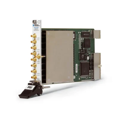
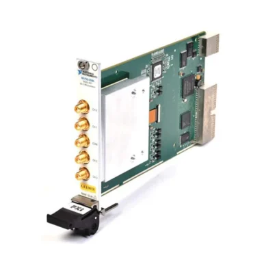
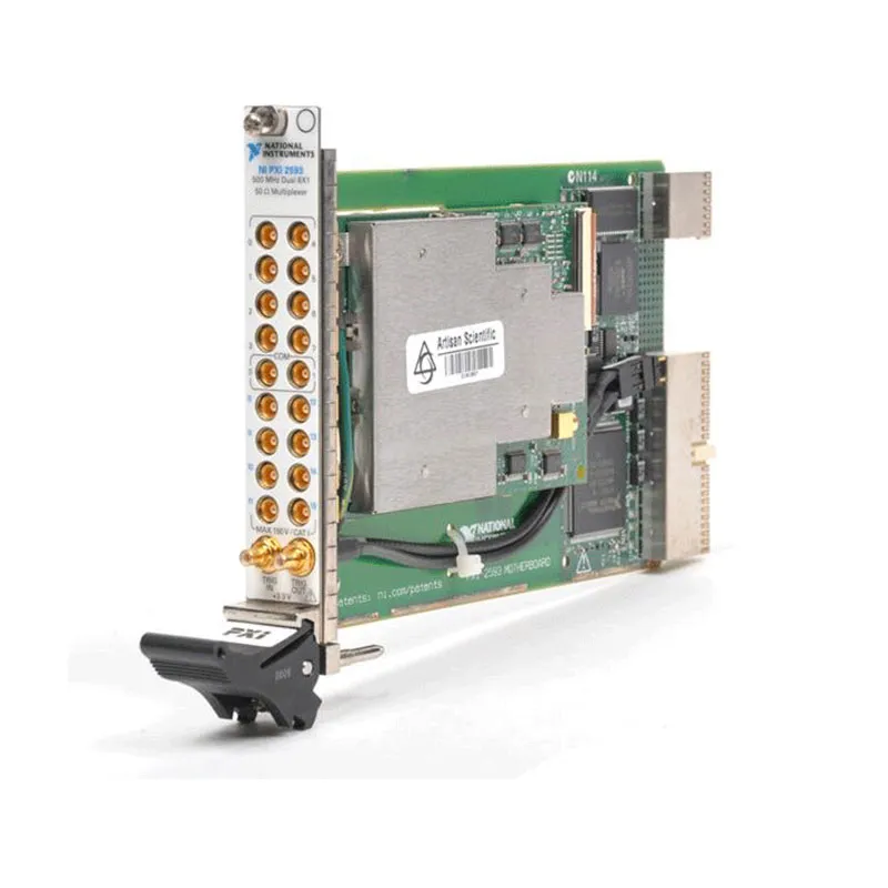
PXI-2593 16-Channel 500 MHz RF Multiplexer Switch
The PXI-2593 is a high-density 50 Ω PXI RF multiplexer designed to route signals from DC to 500 MHz. It combines 16 input channels with flexible electromechanical relay architecture and compact MCX front-panel connections.
The module can operate as an unterminated 16×1 multiplexer, dual 8×1 multiplexer, externally terminated multiplexer or dimensionally flexible sparse matrix. This makes it suitable for RF production testing, video routing, communications test and automated sharing of signal generators or digitizers.
Key Features of the PXI-2593
- 16-channel high-density RF multiplexer
- DC to 500 MHz specified operating range
- 50 Ω characteristic impedance
- Configurable 16×1 and dual 8×1 topologies
- Externally terminated 8×1 and dual 4×1 configurations
- Independent topology for flexible sparse matrices
- 10 W maximum RF carry power
- 150 V peak maximum CAT I signal voltage
- Electromechanical latching relays
- Low insertion loss and high isolation
- 18 MCX front-panel connectors
- PXI and front-panel hardware triggers
- NI-SWITCH and NI Switch Executive support
PXI-2593 Technical Specifications
| Product Model | PXI-2593 |
|---|---|
| Part Number | 778793-01 |
| Product Type | PXI RF multiplexer switch |
| Channel Count | 16 channels plus two common connections |
| Characteristic Impedance | 50 Ω |
| Specified Frequency Range | DC to 500 MHz |
| Typical -3 dB Bandwidth | Greater than 900 MHz for 8×1; greater than 750 MHz for 16×1 |
| Supported Topologies | 16×1, dual 8×1, terminated 8×1, terminated dual 4×1 and independent |
| Maximum Signal Voltage | 150 V peak, CAT I |
| Maximum Switching Current | 0.5 A |
| Maximum Carry Current | 1 A |
| Maximum RF Carry Power | 10 W through 500 MHz |
| Initial DC Path Resistance | Less than 1 Ω |
| Typical Relay Operate Time | 2.4 ms |
| Maximum Relay Operate Time | 4.4 ms |
| Mechanical Relay Life | 5 × 10⁷ operations |
| Electrical Relay Life | 3 × 10⁵ operations at the specified reference load |
| RF Connectors | 18 MCX jacks |
| Trigger Connectors | Two SMB jacks |
| Module Format | 3U, one-slot PXI module |
PXI-2593 Part Number and Accessories
| Item | Part Number | Description |
|---|---|---|
| PXI-2593 | 778793-01 | 16-channel 500 MHz 50 Ω RF multiplexer |
| MCX-MCX Cable | 188374-0R15 | 15 cm, 50 Ω MCX male-to-male coaxial cable |
| MCX-MCX Cable | 188374-01 | 1 m, 50 Ω MCX male-to-male coaxial cable |
| 50 Ω MCX Terminator | 778831-01 | External termination for supported terminated topologies |
16×1 RF Multiplexer Architecture
In the 16×1 topology, any one of 16 input channels can be connected to the common terminal. This permits one signal generator, digitizer, frequency counter or RF measurement instrument to be shared among multiple test points.
Because the module uses break-before-make switching, the previous path is disconnected before a new route is established.
Dual 8×1 Operation
The PXI-2593 can be divided into two independent 8×1 multiplexer banks. Dual-bank operation supports two separate instruments or two signal groups within a single module.
Keeping unrelated signal paths in separate banks can simplify cabling and reduce the number of modules required in a production system.
Externally Terminated Configurations
External 50 Ω MCX terminators can be added to designated channels to create terminated 8×1 or dual 4×1 configurations. Termination helps preserve a defined impedance for inactive paths and can reduce unwanted reflections.
Install the terminators according to the topology diagram. Incorrect placement can create an unexpected load on the source or measurement instrument.
Independent and Sparse-Matrix Routing
The independent topology exposes the underlying relays so that users can create flexible signal routes rather than operating only as a conventional multiplexer.
This permits sparse-matrix configurations for applications that require selected connections between groups of RF inputs and outputs without a full crosspoint matrix.
RF Performance Considerations
Overall measurement performance depends on the module, MCX cables, adapters, test fixture and DUT connections. Each additional cable or switch path contributes insertion loss, mismatch and propagation delay.
Use high-quality 50 Ω cabling, minimize unnecessary adapters and calibrate the measurement plane at the fixture whenever the application requires accurate amplitude or phase results.
PXI-2593 Applications
- Automated RF production testing
- RF signal-generator distribution
- Digitizer and oscilloscope input selection
- Video signal routing
- Communications equipment testing
- Filter and amplifier characterization
- Multi-DUT testing
- Frequency-counter input selection
- Flexible sparse RF matrices
- Laboratory RF automation
Integration with PXI RF Instruments
The PXI-2593 can route signals to a PXI-5124 digitizer, an RF signal generator or another 50 Ω measurement instrument. Software selects the RF path before the instrument generates or acquires the signal.
Hardware triggering can coordinate relay operations with other PXI modules, helping create repeatable automated sequences.
NI-SWITCH Software Support
NI-SWITCH provides control over multiplexer routes, independent relays, triggers and scan lists. NI Switch Executive can combine several modules into named virtual routes.
Relay-count information should be monitored in high-throughput systems so frequently used paths can be identified before contact wear affects measurement performance.
PXI-2593 Troubleshooting
The RF signal is missing
Verify the selected topology and route. Check that the correct common connector is being used and inspect MCX cables for incomplete engagement.
Insertion loss is higher than expected
Measure every cable and adapter separately. Confirm that the system uses 50 Ω components and that the signal frequency remains within the required operating range.
The signal shows excessive reflection
Check the source and load impedance, cable condition and external terminators. An incorrectly terminated path can cause a significant mismatch.
A terminated topology does not work correctly
Confirm that each 50 Ω terminator is installed on the channel specified in the NI topology diagram.
Measurements vary after repeated switching
Inspect the affected relay path, review relay counts and compare the path with a less frequently used channel. Also check connector repeatability and cable movement.
PXI-2593 vs PXIe-2593
| Feature | PXI-2593 | PXIe-2593 |
|---|---|---|
| Bus Platform | PXI hybrid-compatible | PXI Express |
| Frequency Range | DC to 500 MHz | DC to 500 MHz |
| RF Connections | MCX | MCX |
| Best Suited For | Existing PXI systems | PXI Express systems and new integrations |
Recommended Related Products
- PXIe-2593 RF Multiplexer
- PXI-2594 4 GHz RF Multiplexer
- PXI-2595 4 GHz RF Multiplexer
- PXI-2543 RF Switch
- PXI-5124 Digitizer
- View More NI PXI Modules
Frequently Asked Questions
What is the PXI-2593?
The PXI-2593 is a 16-channel, 500 MHz, 50 Ω PXI RF multiplexer and configurable sparse-matrix switch.
Which topologies are available?
Supported configurations include 16×1, dual 8×1, terminated 8×1, terminated dual 4×1 and independent topologies.
What is the maximum RF carry power?
The module can carry up to 10 W of RF power through 500 MHz when operated within the complete specifications.
Which connector does it use?
The RF signal connections use compact 50 Ω MCX jacks.
Can it be configured as a sparse matrix?
Yes. The independent relay topology supports dimensionally flexible sparse-matrix routing.
What is the PXI-2593 part number?
The commonly listed NI ordering part number is 778793-01.
Request a Quote for the PXI-2593
Contact us for current pricing and availability for the PXI-2593 500 MHz RF Multiplexer. We can also help select MCX cables, terminators, PXI chassis and alternative RF switch modules.















