






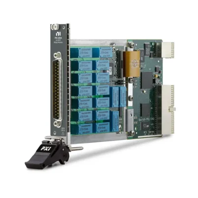
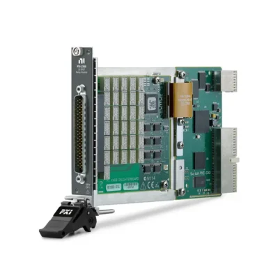
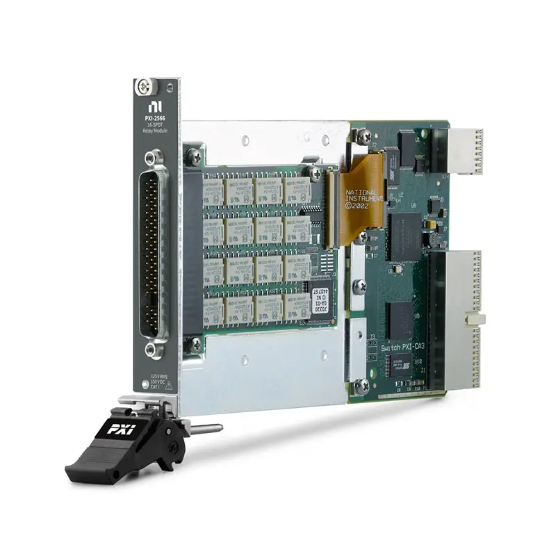
PXI-2566 General-Purpose Relay Module
The PXI-2566 is a 16-channel general-purpose PXI relay module featuring independent nonlatching SPDT Form C electromechanical relays. Each channel provides normally closed, normally open and common terminals for flexible signal switching and control.
With switching currents up to 2 A, carrying currents up to 5 A and a typical bandwidth of at least 70 MHz, the PXI-2566 is suitable for automated test equipment, control systems, load switching and signal-routing applications.
Key Features of the PXI-2566
- 16 independent SPDT Form C relay channels
- Configurable as eight DPDT relay channels
- Maximum switching current of 2 A per channel
- Maximum carry current of 5 A per channel
- Up to 150 VDC or 125 VAC switching, depending on version
- Maximum switching power of 60 W or 62.5 VA
- Typical bandwidth of at least 70 MHz
- Low initial DC path resistance below 0.1 Ω
- Low thermal EMF below 13 μV typical
- Maximum switching rate of 115 cycles/s
- Electromechanical nonlatching relays
- PXI and front-panel triggering
- Field-replaceable relays
- Single-slot 3U PXI module
PXI-2566 Technical Specifications
| Product Model | PXI-2566 |
|---|---|
| Product Type | General-Purpose Relay Module |
| Bus Type | PXI Hybrid |
| Primary Topology | 16-channel SPDT, nonlatching |
| Alternative Topology | 8-channel DPDT |
| Contact Arrangement | Normally closed, normally open and common |
| Maximum Switching Voltage | Up to 150 VDC or 125 VAC, version dependent |
| Maximum Switching Current | 2 A DC or AC per channel |
| Maximum Carry Current | 5 A DC or AC per channel |
| Maximum Switching Power | 60 W or 62.5 VA per channel |
| Initial DC Path Resistance | Less than 0.1 Ω |
| Initial Path Resistance with TB-2666 | Less than 0.19 Ω |
| Thermal EMF | Less than 13 μV typical |
| Minimum Switching Capacity | 10 μA at 10 mVDC |
| Typical Bandwidth | At least 70 MHz |
| Bandwidth with TB-2666 | At least 10 MHz typical |
| Typical Relay Operate Time | 2 ms |
| Maximum Relay Operate Time | 4.4 ms |
| Maximum Cycle Speed | 115 cycles/s |
| Mechanical Relay Life | 1 × 10⁸ cycles |
| Relay Type | Electromechanical, nonlatching |
| I/O Connector | 62-pin male D-Sub |
| PXI Slots Required | 1 |
| Operating Temperature | 0°C to 55°C |
| Dimensions | 21.6 × 2.0 × 13.0 cm |
| Weight | Approximately 250 g |
PXI-2566 Part Numbers and Accessories
| Model or Accessory | Part Number | Description |
|---|---|---|
| PXI-2566 | 778572-66 | 16-channel SPDT relay module, 150 VDC version |
| PXI-2566 | 778573-66 | 16-channel SPDT relay module, 60 VDC version |
| TB-2666 | 778717-66 | Screw-terminal block for PXI-2566 |
| Backshell and Connector Kit | 778720-01 | Connector kit for building a custom PXI-2566 cable assembly |
PXI-2566 Voltage Versions
The PXI-2566 is available under two orderable part numbers. Part number 778572-66 provides a maximum DC switching voltage of 150 V, while part number 778573-66 is listed with a maximum DC switching voltage of 60 V.
Both versions provide 16 SPDT relays, 2 A maximum switching current, 5 A maximum carry current and 70 MHz typical bandwidth. Confirm the required voltage rating and exact part number before ordering.
SPDT and DPDT Relay Configurations
In its standard configuration, the PXI-2566 provides 16 independent SPDT Form C relays. Each relay connects its common terminal to either its normally closed or normally open terminal.
Pairs of SPDT channels can be controlled together to create eight DPDT switching functions. This arrangement is useful when two conductors must be switched simultaneously, such as signal-and-return connections or polarity-selection circuits.
High-Current Signal Switching
Each PXI-2566 channel can switch currents up to 2 A and carry currents up to 5 A. At ambient temperatures of 25°C or lower, all 16 channels can operate simultaneously at the maximum 2 A switching current.
Up to nine channels can simultaneously carry 5 A at temperatures of 25°C or lower. At higher temperatures or when several channels carry elevated current, the module’s load-derating requirements must be applied.
Switching Power and Load Limits
The maximum switching power is 60 W for DC loads or 62.5 VA for AC loads through 60 Hz. Voltage, current and power ratings are separate limits and must all be satisfied for the connected load.
Switching inductive devices such as motors, relays and solenoids can generate high-voltage transients. Appropriate flyback diodes, snubbers or other suppression devices should be installed to protect the module and maintain relay life.
Low-Resistance and Low-Level Signal Routing
The PXI-2566 provides an initial DC path resistance below 0.1 Ω without the terminal block. When used with the TB-2666, initial screw-terminal-to-screw-terminal path resistance is below 0.19 Ω.
A typical thermal EMF below 13 μV helps reduce errors when routing low-level DC signals. The module’s minimum switching capacity is 10 μA at 10 mVDC.
70 MHz Signal Bandwidth
The PXI-2566 provides a typical bandwidth of at least 70 MHz in a 50 Ω system. When the TB-2666 screw-terminal block is included, typical bandwidth is reduced to at least 10 MHz.
Actual system bandwidth depends on topology, cabling, terminal hardware, source impedance, load impedance and the physical layout of the connected test fixture.
Hardware-Triggered Operation
The PXI-2566 supports input and output triggering through PXI trigger lines 0 through 7 and front-panel connections. This allows relay operations to be coordinated with measurement instruments and automated test sequences.
Output-trigger pulse width is programmable from 1 μs to 62 μs. The maximum switching rate is 115 cycles per second, although some applications may require additional settling time.
Typical PXI-2566 Applications
- Automated test equipment
- High-current signal routing
- Power supply and load selection
- Motor and solenoid control
- Battery test systems
- Electronic component testing
- Fault insertion and simulation
- Production functional testing
- Industrial control and monitoring
- Signal polarity selection
- General-purpose laboratory switching
NI-SWITCH Software Support
The PXI-2566 is controlled through the NI-SWITCH instrument driver. NI-SWITCH provides APIs for relay control, route management, scanning, triggering and relay monitoring.
NI Switch Executive can be used to create named routes and simplify larger switching systems. Compatible programming environments include LabVIEW, LabWindows/CVI, C and supported Microsoft development tools.
TB-2666 Terminal Block
The TB-2666, part number 778717-66, provides screw-terminal access to the PXI-2566 relay contacts. It is suitable for prototyping and permanent installations that require field wiring.
The TB-2666 increases total path resistance and reduces the available signal bandwidth compared with a direct custom cable connection. These effects should be considered when routing low-resistance or higher-frequency signals.
PXI Chassis Integration
The PXI-2566 occupies one 3U PXI or compatible PXI Hybrid slot. It can be combined with digital multimeters, source measurement units, power supplies, data acquisition devices and other PXI instruments.
Maintain adequate chassis airflow and install filler panels in unused slots. When carrying high currents on multiple channels, verify the module’s temperature-dependent load-derating requirements.
Safety Considerations
The 150 V version is rated for Measurement Category I signals and must not be connected directly to Category II, III or IV circuits or building mains installations. Standard 115 V and 230 V wall outlets are not valid signal sources for this module.
When hazardous voltage above 42.4 V peak or 60 VDC is connected to any relay terminal, safety extra-low-voltage signals must not be connected to other relay terminals on the same module.
PXI-2566 Troubleshooting
The module is not detected in NI MAX
Confirm that the PXI-2566 is fully installed in a compatible PXI or PXI Hybrid slot. Verify the chassis, controller and NI-SWITCH driver, then refresh the hardware list in NI Measurement & Automation Explorer.
A relay remains in the NC position after power is removed
The PXI-2566 uses nonlatching relays. When relay-coil power is removed, each channel returns to its normally closed state. This is the expected power-off behavior.
The voltage drop across a closed channel is too high
Check the switched current and measure the complete path resistance, including the relay, terminal block, cable and connectors. Review the relay count because contact resistance can increase rapidly near the end of relay life.
The relay switches but the load does not operate
Verify the COM, NO and NC wiring and confirm that the correct relay channel is being controlled. Check the load voltage, current and return path independently from the switch module.
The module becomes hot when several loads are connected
Calculate the combined current load across all active channels and apply the ambient-temperature derating requirements. Reduce the number of high-current channels or improve chassis cooling where necessary.
Relay operation is unreliable with an inductive load
Add suitable transient suppression across the load or switching device. Motors, solenoids and relay coils can produce voltage spikes that exceed the PXI-2566 rating and reduce relay life.
PXI-2566 Compared with Related Relay Modules
| Model | Relay Configuration | Channel Count | Best Suited For |
|---|---|---|---|
| PXI-2566 | SPDT or paired DPDT | 16 SPDT or 8 DPDT | Flexible high-current Form C switching |
| PXI-2565 | SPST | 16 | Simple independent on/off switching |
| PXI-2568 | SPST or DPST | 31 SPST or 15 DPST | Higher-density general-purpose switching |
| PXI-2570 | SPDT | 40 | Higher-density Form C relay systems |
| PXI-2571 | SPDT | 66 | Maximum SPDT channel density |
| PXI-2586 | SPST or DPST | 10 SPST or 5 DPST | Higher-current power switching |
Recommended Related Products
- PXI-2565 General-Purpose Relay Module – A 16-channel SPST module for independent on/off switching.
- PXI-2568 General-Purpose Relay Module – A higher-density SPST and DPST switching option.
- PXI-2570 SPDT Relay Module – A 40-channel alternative for systems requiring more Form C relays.
- PXI-2571 SPDT Relay Module – A high-density 66-channel relay module.
- PXI-2586 High-Current Relay Module – A power-switching alternative for applications requiring higher current capacity.
- PXIe-1092 PXI Express Chassis – A modular chassis for automated switching and measurement systems.
Additional switching and signal-routing products are available in the NI PXI Modules category.
Selecting the PXI-2566
Choose the PXI-2566 when an application requires 16 independently controlled Form C relays, switching currents up to 2 A and carrying currents up to 5 A. It is especially useful when each signal must be selectable between normally closed and normally open paths.
Choose the correct orderable version according to the required DC voltage rating. For higher relay density, consider the PXI-2570 or PXI-2571. For higher-current power switching, consider the PXI-2586.
Why Choose the PXI-2566?
- Provides 16 independent SPDT Form C relays
- Can be configured for eight DPDT switching functions
- Handles up to 2 A switching and 5 A carrying current
- Provides low path resistance and low thermal offset
- Supports hardware-triggered automated switching
- Uses field-replaceable electromechanical relays
- Integrates with NI-SWITCH and NI Switch Executive
Frequently Asked Questions
What is the PXI-2566 used for?
The PXI-2566 switches, routes and controls medium-power electrical signals in automated test, industrial control, battery testing and electronic validation systems.
How many relays does the PXI-2566 provide?
The module provides 16 independent SPDT Form C relays. These relays can also be paired to create eight DPDT channels.
What is the maximum switching current?
Each channel can switch up to 2 A DC or AC within the applicable voltage and power limits.
What is the maximum carry current?
Each channel can carry up to 5 A. The number of channels that can simultaneously carry high current depends on ambient temperature and load derating.
What is the difference between the two PXI-2566 part numbers?
Part number 778572-66 is the 150 VDC version, while part number 778573-66 is listed as the 60 VDC version. Both provide 16 SPDT channels and 2 A switching current.
Which terminal block is compatible with the PXI-2566?
The recommended terminal block is the TB-2666, part number 778717-66.
Are the PXI-2566 relays latching?
No. The module uses nonlatching relays that return to their normally closed positions when relay-coil power is removed.
Can the PXI-2566 switch building mains voltage?
No. The module is intended for Measurement Category I signals and must not be connected directly to Category II, III or IV mains circuits.
Request a Quote for the PXI-2566
Contact us for current availability, lead time and project pricing for the PXI-2566 General-Purpose Relay Module. Please provide the required voltage rating or exact part number so we can verify the correct configuration, compatible terminal block and related system accessories.















