






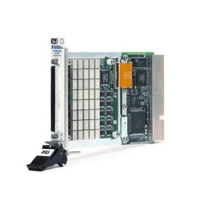
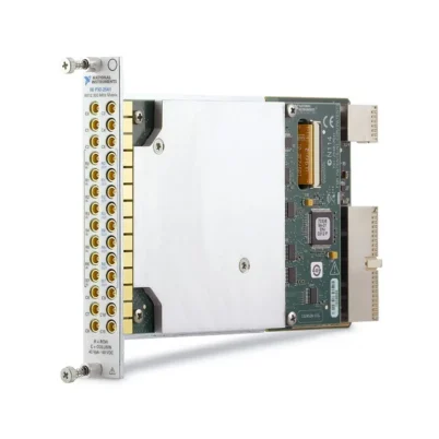
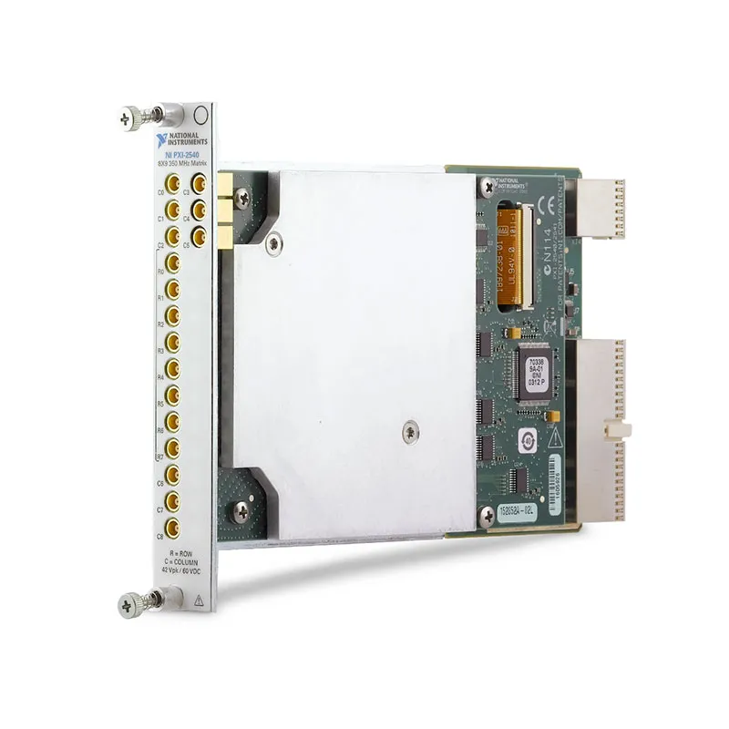
PXI-2540 350 MHz 8×9 RF Matrix Switch Module
The PXI-2540 is an 8×9, 50 Ω PXI RF matrix switch module designed to route RF, video and high-frequency test signals between multiple instruments and devices under test. Its matrix contains eight rows, nine columns and 72 crosspoints, providing flexible software-controlled signal distribution in a single-slot PXI module.
The PXI-2540 uses nonlatching reed relays and a nonblocking matrix architecture. Any row can connect to any column, and multiple crosspoints can operate simultaneously when the resulting electrical connections and RF power remain within the module ratings.
With a specified operating range through 350 MHz, 60 VDC maximum switching voltage, 0.5 A per-channel current and 10 W RF or DC power capacity, the module is suitable for routing signals between digitizers, oscilloscopes, function generators, RF generators, analyzers and automated test fixtures.
Key Features of the PXI-2540
- 8×9 nonblocking RF matrix topology
- 72 independently controlled crosspoints
- 350 MHz switch bandwidth
- 50 Ω nominal characteristic impedance
- 60 VDC maximum switching voltage
- 42.4 V peak maximum AC switching voltage
- 0.5 A maximum switching or carry current per channel
- 10 W maximum DC switching or carry power per channel
- 10 W maximum RF power per channel
- Less than 3 dB insertion loss through 350 MHz
- Greater than 75 dB typical open-channel isolation
- Less than -35 dB typical crosstalk
- Less than 6 ns typical propagation delay
- Nonlatching rhodium-contact reed relays
- Isolation relays for unused matrix sections
- Hardware triggering through the PXI backplane
- 17 front-panel MCX connectors
- NI-SWITCH and NI Switch Executive support
PXI-2540 Technical Specifications
| Product Model | PXI-2540 |
|---|---|
| Part Number | 778572-40 |
| Assembly Number | 153715-01L |
| Product Type | PXI RF matrix switch module |
| Matrix Topology | 8 rows × 9 columns |
| Number of Crosspoints | 72 |
| Matrix Design | Nonblocking |
| Switch Bandwidth | 350 MHz |
| Characteristic Impedance | 50 Ω nominal |
| Maximum Switching Voltage | 60 VDC or 42.4 V peak AC |
| Maximum Switching or Carry Current | 0.5 A per channel |
| Maximum DC Power | 10 W per channel |
| Maximum RF Power | 10 W per channel in a 50 Ω system |
| Simultaneous Channels at Maximum RF Power | Three channels through 350 MHz for the PXI version |
| Initial DC Path Resistance | Less than 2.1 Ω typical |
| End-of-Life Path Resistance | 3.1 Ω or greater typical |
| Insertion Loss | Less than 3 dB through 350 MHz; less than 2.3 dB typical |
| VSWR | Less than 2.2 through 350 MHz; less than 1.6 typical |
| Open-Channel Isolation | Greater than 75 dB typical through 350 MHz |
| Crosstalk | Less than -35 dB typical through 350 MHz |
| Propagation Delay | Less than 6 ns typical |
| Channel-to-Channel Skew | Less than 2 ns typical |
| Relay Type | Nonlatching reed relay |
| Relay Contact Material | Rhodium |
| Maximum Operate Time | 0.25 ms |
| Maximum Release Time | 0.25 ms |
| Scan Rate | Up to 100 cycles/s |
| Simultaneous Relay Drive Limit | 40 relays |
| Mechanical Relay Life | 1 × 10⁹ cycles typical |
| Input Trigger Sources | PXI trigger lines 0 through 7 |
| Minimum Trigger Pulse Width | 150 ns with digital filtering enabled |
| Front-Panel Connectors | 17 female MCX jacks |
| Software Support | NI-SWITCH and NI Switch Executive |
| Bus Interface | PXI |
| Module Format | 3U, single-slot PXI/cPCI module |
| Dimensions | 21.6 × 2.0 × 13.0 cm |
| Weight | 380 g |
| Operating Temperature | 0°C to 55°C |
| Storage Temperature | -20°C to 70°C |
| Product Status | Discontinued by NI |
PXI-2540 Part Number and Compatible Cables
| Item | Part Number | Description |
|---|---|---|
| PXI-2540 | 778572-40 | 350 MHz, 8×9, 50 Ω PXI RF matrix switch module |
| MCX-to-MCX Cable | 188374-0R15 | 15 cm MCX male to MCX male RF cable |
| MCX-to-MCX Cable | 188374-0R3 | 30 cm MCX male to MCX male RF cable |
| MCX-to-MCX Cable | 188374-01 | 1 m MCX male to MCX male RF cable |
| MCX-to-BNC Cable | 188375-0R3 | 30 cm MCX male to BNC male RF cable |
| MCX-to-BNC Cable | 188375-01 | 1 m MCX male to BNC male RF cable |
| MCX-to-SMB Cable | 188376-0R3 | 30 cm MCX male to SMB female RF cable |
| MCX-to-SMB Cable | 188376-01 | 1 m MCX male to SMB female RF cable |
| MCX-to-SMA Cable | 188377-01 | 1 m MCX male to SMA male RF cable |
The PXI-2540 has 17 front-panel MCX jacks corresponding to its eight rows and nine columns. Verify the connector gender, destination connector, cable length, frequency range and impedance before selecting cables.
8×9 RF Matrix Architecture
The PXI-2540 contains eight row connections and nine column connections. Each row can connect to any column through a software-controlled relay crosspoint, providing 72 possible row-to-column routes.
A matrix architecture is more flexible than a standard multiplexer because multiple connections can be active at the same time. For example, several signal generators can be connected to different analyzers or devices under test during the same automated sequence.
Before closing multiple crosspoints, verify that the selected routes will not connect incompatible sources together. Connecting two active RF generators to the same matrix node can damage the sources or produce invalid test results.
Nonblocking Signal Routing
The nonblocking design allows any available row to connect to any available column without requiring the signal to pass through another selected route. This makes the PXI-2540 suitable for test systems that must create different RF connection patterns dynamically.
More than one row can be connected to a column, and more than one column can be connected to a row. Whether such a connection is electrically valid depends on the connected instruments, termination and intended test architecture.
72 RF Crosspoints
Each intersection between a row and column is an independently controlled crosspoint. With eight rows and nine columns, the PXI-2540 provides 72 crosspoints in a single PXI slot.
Test software can open or close individual crosspoints, establish named routes or execute predefined scan sequences. The matrix can therefore replace many manual RF patch connections in production and laboratory systems.
350 MHz RF Bandwidth
The PXI-2540 is designed for signal routing through 350 MHz. It can switch DC, low-frequency, video, IF and moderate-frequency RF signals between instruments and test fixtures.
Actual system bandwidth depends on more than the switch module. Cable length, cable quality, adapters, source impedance, load impedance and fixture design all affect insertion loss and frequency response.
Use 50 Ω cables and correctly terminated instruments when the application requires the published RF performance.
50 Ω Characteristic Impedance
The PXI-2540 signal paths have a nominal 50 Ω characteristic impedance. This matches the standard impedance used by many RF generators, spectrum analyzers, digitizers, oscilloscopes and communications test instruments.
Connecting high-impedance or 75 Ω equipment may produce reflections and amplitude errors. Where different impedances must be connected, include appropriate matching or conversion components in the test system.
Insertion Loss
Insertion loss is specified at less than 3 dB through 350 MHz, with less than 2.3 dB typical performance. The total signal loss in an installed system also includes cables, adapters and fixtures.
For amplitude-critical measurements, characterize each complete route and apply path-loss correction in the test software or measurement instrument.
VSWR and Signal Reflections
The PXI-2540 has a specified VSWR below 2.2 through 350 MHz, with typical performance below 1.6. Proper 50 Ω termination and high-quality cables help minimize reflections.
Loose, damaged or contaminated MCX connectors can degrade return loss and measurement repeatability. Inspect RF cables regularly and replace cables that show intermittent performance.
Open-Channel Isolation
Typical open-channel isolation is greater than 75 dB through 350 MHz. High isolation helps prevent inactive sources and instruments from coupling into the active measurement path.
The module includes isolation relays that disconnect unused matrix sections. This design helps preserve RF isolation even though the PXI-2540 contains a high density of crosspoints.
Crosstalk Performance
Typical crosstalk is below -35 dB through 350 MHz. Crosstalk performance depends on signal frequency, amplitude, selected routes, cable arrangement and termination.
For sensitive measurements, avoid routing a low-level signal next to a much stronger signal when the test configuration allows an alternative path. External cable separation and shielding are also important.
Propagation Delay and Channel Skew
Typical propagation delay through the PXI-2540 is less than 6 ns. Typical channel-to-channel skew is less than 2 ns.
These characteristics are useful when routing pulses, clocks or synchronized signals. The complete system delay and skew must also include all external cables and fixture paths.
60 V and 0.5 A Switching Capability
The module supports switching voltages up to 60 VDC or 42.4 V peak AC and currents up to 0.5 A per channel. Maximum DC switching or carry power is 10 W per channel.
Voltage, current and power limits apply simultaneously. A signal below the maximum voltage can still exceed the switch rating if its current or power is too high.
RF Power Handling
The PXI-2540 supports RF power up to 10 W per channel in a 50 Ω system, subject to derating for frequency and the number of simultaneous powered channels. For the PXI version, as many as three channels can operate at the maximum RF power through 350 MHz under the specified conditions.
Do not assume that every crosspoint can carry 10 W simultaneously. Consult the official RF power derating curves when several high-power paths will be active.
Avoid Switching Active RF Signals
NI recommends against switching an active RF source whenever possible. During relay operation, the signal path is momentarily unterminated, which can reflect power toward the source.
Some RF generators and amplifiers can be damaged by high reflected power. Reduce or disable the RF output before changing routes, then restore the signal after the relays have settled.
Fast Nonlatching Reed Relays
The PXI-2540 uses nonlatching reed relays with rhodium contacts. Maximum relay operate and release times are 0.25 ms, although the connected signal and instrument may require additional settling time.
Nonlatching relays return to their default open state when power is removed. This provides a predictable disconnected condition after the PXI system is shut down.
Relay Life and Protection
Typical mechanical relay life is 1 × 10⁹ cycles with no electrical load. Representative electrical life is approximately 1 × 10⁷ cycles at 10 V and 100 mA and 5 × 10⁶ cycles at 20 V and 500 mA under the documented resistive-load conditions.
Capacitive loads can produce high inrush current, while inductive loads can create damaging flyback voltage. Use current limiting, snubbers or other suitable protection when routing reactive circuits.
Hardware Triggering
The PXI-2540 can receive and export triggers through PXI trigger lines 0 through 7. Hardware triggers allow switch operations to be coordinated with digitizers, function generators and other PXI instruments.
Deterministic triggering can improve repeatability and test throughput by reducing dependence on software command timing.
NI-SWITCH Software Support
The PXI-2540 is controlled through the NI-SWITCH instrument driver. NI-SWITCH provides functions for initialization, route connection, route disconnection, scan-list control, triggering and relay monitoring.
The driver supports LabVIEW, LabWindows/CVI and compatible text-based programming environments. Verify driver and operating-system compatibility when maintaining an older PXI controller.
NI Switch Executive Integration
NI Switch Executive allows developers to define meaningful route names rather than addressing rows, columns and relays directly in application code. Named routes make large automated test systems easier to understand and maintain.
Route groups can also coordinate connections across multiple switch modules. This is useful when an RF test platform combines the PXI-2540 with multiplexers, transfer switches or additional matrices.
Typical PXI-2540 Applications
- RF signal routing through 350 MHz
- Automated test equipment
- Production functional testing
- Digitizer input selection
- Function generator distribution
- RF generator and analyzer routing
- Oscilloscope channel selection
- Video signal switching
- Intermediate-frequency signal routing
- Communications device testing
- PCB and electronic assembly validation
- Multidevice production testing
- Laboratory RF automation
- Test-fixture signal distribution
Routing Signals Between RF Instruments
The PXI-2540 can route several RF or high-frequency instruments to multiple devices or test points. A system might connect function generators to selected DUT inputs while routing DUT outputs to digitizers or analyzers.
Software-controlled matrix routes eliminate repetitive manual cable changes and allow the test system to reconfigure itself for different products or measurement stages.
Digitizer and Oscilloscope Input Selection
The nine matrix columns can represent DUT signals while the rows connect to digitizers, oscilloscopes or other acquisition instruments. Software selects which test point reaches each measurement channel.
Account for switch and cable insertion loss when measuring amplitude. Fast signals may also require delay and skew correction.
Function Generator Distribution
A function generator can be connected to different DUT inputs without manual reconnection. Multiple generators can also be assigned to separate device channels through independent matrix routes.
Do not close routes that connect generator outputs together unless the sources are specifically designed to operate in that configuration.
PXI-2540 Troubleshooting
The PXI-2540 Is Not Detected in NI MAX
Confirm that the module is fully installed in a compatible PXI or hybrid slot. Check chassis power, controller communication and NI-SWITCH installation, then restart the chassis and rescan for devices.
A Route Cannot Be Connected
Verify the row and column channel names and check for an existing route conflict. Confirm that the requested connection is supported by the 8×9 matrix topology.
The RF Signal Is Weaker Than Expected
Account for switch insertion loss, cable loss, adapters and fixture attenuation. Inspect the MCX connectors and measure the complete route with a network analyzer when accurate path characterization is required.
The Signal Has Excessive Reflections
Confirm that the source, load, cables and switch path use 50 Ω impedance. Replace damaged cables and remove unnecessary adapters. Check that unused external lines are terminated appropriately.
An Inactive Signal Appears at the Output
Review all closed routes and check for external cable coupling. Strong signals can couple into sensitive paths through cables or fixtures even when the module meets its isolation specification.
The RF Source Shuts Down During Switching
The source may be detecting excessive reflected power while the relay path is momentarily unterminated. Disable or reduce the RF output before changing routes and restore the signal after relay settling.
The Module Reports Unexpected Path Resistance
Inspect the cables and MCX connectors before evaluating the relay. Compare the affected route with another crosspoint and review relay-count information. Increasing resistance may indicate relay wear.
The Triggered Scan Does Not Advance
Verify the PXI trigger line, trigger direction and input pulse width. Ensure that the scan list has been initiated before the first trigger is generated.
Relay Life Is Shorter Than Expected
Check whether the module is switching active RF power, capacitive inrush current or inductive loads. Use cold switching and external protection whenever the application permits.
PXI-2540 Comparison with Similar RF Switch Modules
| Model | Primary Configuration | Best Suited For |
|---|---|---|
| PXI-2540 | 350 MHz, 8×9, 50 Ω RF matrix | Maintaining legacy PXI RF matrix systems |
| PXIe-2540 | 350 MHz, 8×9, 50 Ω RF matrix | Current PXI Express systems requiring higher powered-route density |
| PXI-2541 | 100 MHz, 8×9, 50 Ω matrix | Lower-frequency routing with reduced insertion loss requirements |
| PXIe-2541 | 100 MHz, 8×9 PXI Express matrix | Modern low-frequency and IF matrix systems |
| PXI-2593 | 500 MHz-class multiplexer and matrix configurations | Applications requiring a software-configurable RF switching topology |
| PXI-2544 | High-frequency RF multiplexer | Routing one RF signal among several channels rather than full matrix switching |
PXI-2540 vs PXIe-2540
The PXI-2540 and PXIe-2540 provide the same 8×9 matrix arrangement, 72 crosspoints, 350 MHz bandwidth, 50 Ω impedance and 17 MCX connectors. Their main difference is the chassis bus interface and available relay-power capacity.
The PXI-2540 uses part number 778572-40 and supports as many as three simultaneous channels at maximum RF power through 350 MHz. The PXIe-2540 uses part number 780587-40 and supports as many as five simultaneous channels under the corresponding specified conditions.
Select the PXI-2540 for direct replacement in a validated legacy PXI system. Choose the PXIe-2540 for a new PXI Express platform or when additional simultaneous high-power routes are required.
PXI-2540 vs PXI-2541
Both modules use an 8×9, 50 Ω matrix architecture with MCX connections. The PXI-2540 is designed for operation through 350 MHz, while the PXI-2541 is intended for lower-frequency applications.
Choose the PXI-2540 when wider RF bandwidth is required. Consider the PXI-2541 when the application remains within its frequency range and its signal-performance characteristics are a better match.
Recommended Related Products
- PXIe-2540 350 MHz 8×9 RF Matrix Switch Module
- PXI-2541 8×9 RF Matrix Switch Module
- PXIe-2541 8×9 PXI Express RF Matrix Switch Module
- PXI-2593 RF Multiplexer and Matrix Switch Module
- PXI-2544 RF Multiplexer Switch Module
- View More NI PXI and PXI Express Modules
Selecting the Right RF Matrix Switch
Choose the PXI-2540 when the test system requires an 8×9 nonblocking matrix, 350 MHz bandwidth, 50 Ω signal paths and compatibility with an existing PXI chassis. It is particularly appropriate as a direct replacement in a previously validated system.
Select the PXIe-2540 for a new PXI Express platform. Consider the PXI-2541 for lower-frequency matrix routing or a PXI RF multiplexer when the application requires one-to-many selection rather than a complete row-to-column matrix.
Why Choose the PXI-2540?
- Provides 72 RF crosspoints in one PXI slot
- Supports flexible 8×9 nonblocking routing
- Operates through 350 MHz
- Maintains 50 Ω RF signal paths
- Supports RF power up to 10 W per channel
- Provides high open-channel isolation
- Uses fast nonlatching reed relays
- Offers hardware-triggered operation
- Connects through standard MCX RF cables
- Integrates with NI-SWITCH and NI Switch Executive
Frequently Asked Questions
What is the PXI-2540?
The PXI-2540 is a 350 MHz, 8×9, 50 Ω RF matrix switch module with 72 software-controlled crosspoints.
What is the PXI-2540 part number?
The standard NI part number is 778572-40. The newer PXIe-2540 has a different part number, 780587-40.
How many rows and columns does it provide?
The matrix provides eight rows and nine columns.
How many crosspoints are available?
The PXI-2540 provides 72 possible row-to-column crosspoints.
What is the PXI-2540 bandwidth?
The switch is specified for operation through 350 MHz.
What is the characteristic impedance?
The nominal characteristic impedance is 50 Ω.
What are the maximum voltage and current?
The module supports up to 60 VDC or 42.4 V peak AC and 0.5 A per channel, subject to the 10 W power limit.
What type of connectors does it use?
The front panel provides 17 female MCX jacks: eight row connections and nine column connections.
Can multiple matrix routes be active simultaneously?
Yes. Its nonblocking architecture supports multiple simultaneous routes, provided the connections do not create electrical conflicts or exceed the RF power and relay-drive limits.
Can the PXI-2540 switch an active RF signal?
It can carry RF signals within its ratings, but NI recommends reducing or disabling the active RF source before changing relay states because the path is momentarily unterminated during switching.
Which software controls the PXI-2540?
The module is controlled using NI-SWITCH and can be integrated into named-route systems with NI Switch Executive.
Is the PXI-2540 still available from NI?
No. NI identifies the original PXI-2540 as no longer available. Used, refurbished and new-surplus units may still be available through specialized test-equipment suppliers.
Request a Quote for the PXI-2540
Contact us for current availability, condition, testing options and project pricing for the PXI-2540 350 MHz 8×9 RF Matrix Switch Module. We can also help identify compatible MCX cables, PXI chassis, replacement PXIe-2540 modules and related NI RF switches.















