




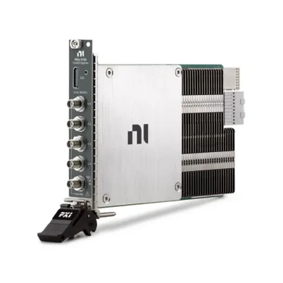
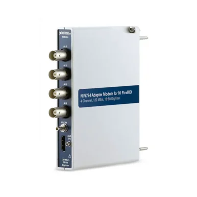

NI-5751B 16-Channel 14-Bit 50 MS/s FlexRIO Digitizer Adapter Module
The NI-5751B is a high-density digitizer adapter module designed for use with NI FlexRIO FPGA modules and Controllers for FlexRIO. It provides 16 simultaneously sampled analog input channels with 14-bit resolution and sample rates up to 50 MS/s per channel, making it suitable for multichannel acquisition, real-time signal processing and custom FPGA-based instrumentation.
Each analog input is single-ended, DC coupled and terminated with a nominal 50 Ω input impedance. The module supports a maximum input voltage swing of 2 Vpp and provides a characteristic analog bandwidth of 26 MHz. These characteristics make the NI-5751B suitable for acquiring baseband, IF, transient and repetitive signals across multiple synchronized channels.
In addition to its analog inputs, the NI-5751B provides eight digital input terminals and eight digital output terminals. An SMB clock input and PXI Express synchronization resources allow designers to create externally clocked or synchronized acquisition systems. The module is identified by NI part number 784061-01.
Key Features of the NI-5751B
- 16 simultaneously sampled analog input channels
- 14-bit analog-to-digital conversion
- Up to 50 MS/s sampling on every analog input channel
- 30 MHz to 50 MHz supported sample-clock range
- 26 MHz characteristic analog input bandwidth
- 2 Vpp maximum analog input voltage swing
- 50 Ω nominal analog input impedance
- Single-ended, DC-coupled analog inputs
- Eight digital input terminals
- Eight digital output terminals
- 1 MHz maximum digital-output toggle frequency with all outputs toggling
- Internal, external and supported PXI Express sample-clock sources
- Front-panel SMB external clock input
- Three 68-pin VHDCI front-panel connectors
- Compatible with all NI FlexRIO FPGA module and Controller for FlexRIO families supported by the NI-5751B
- Socketed CLIP support for direct FPGA access to converter and digital I/O signals
- Multidevice synchronization CLIP available for synchronized systems
High-Density FlexRIO Digitizer Architecture
The NI-5751B is an adapter module rather than a complete standalone digitizer. It must be paired with a compatible FlexRIO FPGA module or Controller for FlexRIO. The adapter supplies the analog conversion, digital I/O and external clock interfaces, while the associated FPGA hardware performs acquisition control, buffering, triggering, digital signal processing and host communication.
This architecture allows the instrument behavior to be customized for a particular application. Instead of being limited to a fixed oscilloscope acquisition engine, developers can implement application-specific triggering, channel selection, filtering, decimation, averaging, spectral processing and data-reduction logic in the FPGA.
The NI-5751B produces one sample from every enabled analog input channel during each sample-clock cycle. At the maximum 50 MHz sample clock, all 16 channels can be digitized at 50 MS/s, creating a substantial aggregate data stream. FPGA processing can reduce the amount of information transferred to the host by extracting only the events, measurements or frequency components required by the application.
NI-5751B Technical Specifications
| Product Model | NI-5751B |
|---|---|
| Part Number | 784061-01 |
| Product Type | Digitizer adapter module for NI FlexRIO |
| Analog Input Channels | 16 simultaneously sampled, single-ended channels |
| ADC Resolution | 14 bits |
| ADC Architecture | Pipelined analog-to-digital converter |
| Maximum Sample Rate | 50 MS/s per channel |
| Sample-Clock Frequency Range | 30 MHz to 50 MHz |
| Analog Input Bandwidth | 26 MHz characteristic, −3 dB |
| Maximum Input Voltage Swing | 2 Vpp |
| Input Impedance | 50 Ω ±2% |
| Input Coupling | DC coupled |
| DC Gain Error | ±2% of input, characteristic |
| DC Offset Error | ±2% of full scale, characteristic |
| Signal-to-Noise Ratio | 71 dB characteristic at 5 MHz and −1 dBFS |
| Spurious-Free Dynamic Range | 73 dB characteristic at 5 MHz and −1 dBFS |
| Total Harmonic Distortion | 73 dB characteristic at 5 MHz and −1 dBFS |
| Digital Inputs | 8 channels |
| Digital Input Logic | 2.0 V minimum high level; 0.8 V maximum low level |
| Digital Outputs | 8 channels |
| Digital Output Levels | 2.4 V minimum high level; 0.55 V maximum low level |
| Maximum Digital Output Current | 1 mA |
| Minimum Digital Output Pulse Width | 10 ns |
| Maximum Digital Output Toggle Rate | 1 MHz with all outputs toggling |
| Sample-Clock Sources | 50 MHz onboard oscillator, supported PXIe_DSTARA synchronization clock or front-panel CLK IN |
| External Clock Connector | SMB |
| External Clock Logic Level | 3.3 V CMOS |
| External Clock Input Impedance | Greater than 50 kΩ |
| External Clock Coupling | DC coupled |
| External Clock Duty Cycle | 45% to 55% |
| Front-Panel Connectors | Three 68-pin VHDCI connectors and one SMB connector |
| Total Power Consumption | 5.37 W maximum from the FlexRIO FPGA module |
| Dimensions | 12.9 × 2.0 × 12.1 cm |
| Weight | 284 g |
| Operating Temperature | 0°C to 55°C |
| Operating Humidity | 10% to 90% RH, noncondensing |
| Maximum Operating Altitude | 2,000 m at 25°C ambient temperature |
16 Simultaneously Sampled Analog Inputs
The NI-5751B digitizes 16 analog signals at the same time. Simultaneous sampling preserves the timing relationship between channels and is important when phase, propagation delay, event sequence or channel-to-channel correlation must be analyzed.
This configuration is useful for multichannel sensor systems, phased experiments, transient recording and parallel electronic-device testing. Because every channel is sampled from the same acquisition clock, software does not need to compensate for the channel skew associated with a multiplexed converter architecture.
14-Bit ADC Resolution
Each analog channel uses a 14-bit pipelined ADC. The additional amplitude resolution compared with lower-resolution high-speed converters helps distinguish smaller changes within the module’s 2 Vpp input range.
The converter data is exposed to LabVIEW FPGA through the NI-5751 CLIP as an I16 value. The 14-bit sample is left justified and padded with two zeros in the least-significant-bit positions. FPGA logic should account for this format when scaling, filtering or comparing acquired values.
50 MS/s Sample Rate
The module supports a sample-clock frequency from 30 MHz to 50 MHz. At the maximum setting, it generates 50 million samples per second from each of its 16 analog inputs.
The 50 MS/s rate supports detailed capture of signals within the module’s analog bandwidth. It also gives FPGA algorithms sufficient time resolution for event detection, pulse analysis, waveform averaging and frequency-domain processing.
Applications requiring lower effective output rates can acquire at a supported clock frequency and perform FPGA-based decimation or averaging before transferring data to the host.
26 MHz Analog Bandwidth
The NI-5751B has a characteristic −3 dB analog bandwidth of 26 MHz. It is suitable for DC, baseband and moderate-frequency signals that fit within this analog front-end response.
Sample rate and analog bandwidth describe different parts of system performance. The 50 MS/s rate determines how frequently the waveform is digitized, while the 26 MHz bandwidth describes the frequency response of the analog input path.
Cable loss, source impedance, connectors and test-fixture layout can reduce the usable bandwidth of the completed system. High-frequency connections should therefore use short, impedance-controlled signal paths.
2 Vpp DC-Coupled Inputs
The analog inputs are DC coupled and support a maximum input voltage swing of 2 Vpp. DC coupling allows the digitizer to capture both the time-varying component and the DC level of a signal.
The source must remain within the permitted input range at all times. DC offset, transient overshoot and ringing must be considered in addition to the nominal signal amplitude. External attenuation or signal conditioning may be required for higher-voltage sources.
50 Ω Input Termination
Each analog input has an impedance of 50 Ω ±2%. This termination supports controlled-impedance signal paths and helps reduce reflections when the module is connected through suitable 50 Ω cables and fixtures.
The source must be capable of driving a 50 Ω load. Connecting a high-output-impedance sensor directly to the module can attenuate the signal or change the sensor’s operating behavior. A buffer amplifier or appropriate signal conditioner may be needed in such applications.
Digital Input and Output Resources
The NI-5751B provides eight digital inputs and eight digital outputs through its digital VHDCI connector. These terminals can be used for trigger detection, equipment status, test-fixture control, synchronization markers and communication with external logic.
The digital outputs are intended for logic-level signaling and provide a maximum current of 1 mA. They should not be connected directly to relays, motors, lamps or other power loads. External drivers or interface circuitry must be used when controlling higher-current devices.
Sample-Clock Options
The default clock source is the module’s 50 MHz onboard oscillator. Applications can alternatively use a compatible PXIe_DSTARA synchronization clock or an external sample clock connected to the front-panel SMB connector.
The external CLK IN accepts a 3.3 V CMOS clock between 30 MHz and 50 MHz. It is DC coupled, has an input impedance greater than 50 kΩ and requires a duty cycle between 45% and 55%.
If the external or synchronization-clock frequency is changed while the system is operating, the applicable NI-5751B initialization control must be asserted as described in the FlexRIO documentation.
FPGA Processing and Socketed CLIP
The NI-5751B is supplied with socketed Component-Level Intellectual Property, commonly called CLIP. The standard CLIP exposes all 16 analog inputs, eight digital inputs and eight digital outputs to the FPGA application. It also provides an SPI interface for programming the ADC registers.
Developers can build custom FPGA logic for:
- Level, window and edge triggering
- Pretrigger and post-trigger waveform capture
- Digital filtering and decimation
- FFT and spectral processing
- Channel-to-channel timing analysis
- Peak and pulse detection
- Waveform averaging
- Event counting and classification
- Real-time limit testing
- Data compression and reduction
- Digital trigger and control sequencing
Multidevice Synchronization
NI also provides a multidevice synchronization CLIP for applications containing multiple NI-5751B modules. This implementation uses the PXI Express synchronization resources available through a compatible FlexRIO FPGA carrier.
Synchronized acquisition can expand the system beyond 16 channels while maintaining a controlled relationship between modules. The complete synchronization design must consider clock distribution, trigger routing, FPGA initialization, cable delay and the capabilities of the selected chassis and FlexRIO carrier.
NI-5751B Part Number and Accessories
| Item | Part Number | Description |
|---|---|---|
| NI-5751B | 784061-01 | 16-channel, 14-bit, 50 MS/s FlexRIO digitizer adapter module |
| SHC68-C68-D4 Cable | 196275A-01 | Recommended shielded VHDCI cable for the analog and digital connectors |
| SMB-2147 | Configuration dependent | Shielded analog input accessory providing accessible signal connections |
| SMB-2148 | Configuration dependent | Shielded signal accessory used for NI-5751B testing and debugging |
| Compatible FlexRIO FPGA Module | Model dependent | Required carrier providing the FPGA, bus interface, power and onboard memory resources |
| PXI or PXI Express Chassis | Model dependent | Required when the NI-5751B is paired with a PXI/PXI Express FlexRIO FPGA module |
The NI-5751B adapter is not a complete acquisition system by itself. A compatible FlexRIO FPGA module or Controller for FlexRIO must be included in the configuration. Chassis, controller, cables, terminal accessories and software requirements should be verified before ordering.
SHC68-C68-D4 Cable
NI recommends the SHC68-C68-D4 shielded cable for connecting to the analog and digital VHDCI interfaces. The analog and digital connectors use different pin assignments even though they use the same connector style.
Do not interchange the analog and digital cable connections. An incorrect connection can short digital outputs to ground and may damage the module or connected equipment. Labeling the cables and fixture connectors is recommended for permanent installations.
SMB-2147 and SMB-2148 Accessories
The SMB-2147 and SMB-2148 are shielded accessories that provide convenient connections for testing, debugging and laboratory integration. These accessories help break out the high-density VHDCI interfaces into more accessible signal connections.
Before ordering, confirm the accessory revision, supplied cables, connector gender and required channel mapping. The external accessory and cable must preserve the intended grounding and 50 Ω signal-path characteristics.
Compatible FlexRIO Hardware
The NI-5751B is the updated variant designed for compatibility with all supported FlexRIO FPGA modules and Controllers for FlexRIO. This includes the earlier NI PXI-795xR and PXIe-796xR families as well as supported PXIe-797xR FPGA modules and NI-793xR Controllers for FlexRIO.
Compatibility does not mean that every carrier provides identical performance. FPGA size, onboard DRAM, PCI Express bandwidth, synchronization resources and software support vary by model. Select the carrier according to the processing, buffering and streaming requirements of the application.
NI-5751B Applications
- High-density multichannel data acquisition
- Custom FPGA-based digitizers
- Real-time signal processing
- Transient and pulse capture
- Baseband and intermediate-frequency acquisition
- Multichannel waveform monitoring
- Automated electronic testing
- Radar and communications research
- Physics and scientific instrumentation
- Ultrasonic and acoustic measurement research
- Semiconductor characterization
- Hardware-in-the-loop test systems
- Custom triggering and event detection
- Synchronized multidevice acquisition
Multichannel Signal Acquisition
With 16 simultaneous input channels, the NI-5751B can capture related signals without multiplexing delay. Engineers can compare amplitude, phase, propagation time and event sequence across an entire system.
Typical examples include monitoring multiple outputs of an electronic assembly, acquiring parallel sensor signals and measuring timing relationships between several control or communication paths.
Real-Time FPGA Signal Processing
High-speed acquisition can generate more data than a host computer needs to store continuously. FlexRIO FPGA processing allows the system to analyze the samples before host transfer.
The FPGA can identify events, calculate measurements, perform filtering or transmit only selected waveform segments. This reduces bus traffic and enables deterministic responses that do not depend on the timing behavior of the host operating system.
Custom Triggering
Standard oscilloscopes provide a predefined collection of trigger modes. The NI-5751B and FlexRIO architecture allow developers to implement trigger conditions specifically for the application.
A trigger can combine multiple analog thresholds, digital states, timing windows or sequential events. Once the trigger occurs, FPGA memory and carrier DRAM can be used to preserve the required pretrigger and post-trigger data.
Baseband and IF Acquisition
The 26 MHz analog bandwidth supports direct acquisition of baseband and suitable intermediate-frequency signals. FPGA DSP can perform digital downconversion, filtering, demodulation and spectral analysis.
The signal frequency, image response and required transition band should be evaluated when implementing digital downconversion. External antialias filtering may be required when out-of-band energy could fold into the measurement band.
Automated Test Equipment
The NI-5751B can acquire multiple DUT outputs during functional, production and design-verification testing. Digital I/O lines can coordinate fixture states, trigger sources and other equipment while the analog inputs capture the DUT response.
FPGA-based limit checking can provide fast pass/fail decisions and capture detailed diagnostic data only when an abnormal event is detected.
Scientific and Research Instrumentation
Research systems often require specialized timing, triggering and processing behavior that conventional instruments do not provide. FlexRIO lets developers create a measurement engine matched to the experiment.
Multiple NI-5751B modules can be synchronized when more than 16 channels are required, subject to the clocking and synchronization capabilities of the selected PXI Express platform.
Recommended Related Products
- NI-5752B 32-Channel FlexRIO Digitizer Adapter Module
- NI-5753 16-Channel 120 MS/s FlexRIO Digitizer Adapter Module
- PXIe-7965 FlexRIO FPGA Module
- PXIe-7966 FlexRIO FPGA Module
- PXIe-7975 FlexRIO FPGA Module
- PXIe-7976 FlexRIO FPGA Module
- View More NI PXI and PXI Express Modules
NI-5751B Installation Workflow
Step 1: Verify the Complete System Configuration
Confirm that the NI-5751B, FlexRIO FPGA carrier, chassis, system controller and software versions are mutually compatible. Check that the carrier provides sufficient FPGA logic, onboard memory and host-transfer bandwidth for the intended application.
Step 2: Install the Required Software
Install the supported NI FlexRIO driver and the development software required by the selected FPGA module. Applications that compile customized FPGA code normally require the appropriate LabVIEW FPGA development environment and compilation resources.
Driver and LabVIEW compatibility should be checked before changing an established system because older FlexRIO hardware may require a particular software version.
Step 3: Observe ESD Precautions
Use a grounded wrist strap or another approved antistatic procedure. Keep the module in its antistatic package until installation and never touch exposed connector contacts or circuit-board components.
Step 4: Attach the Adapter to the FlexRIO Module
Power off the chassis or controller and follow the FlexRIO hardware installation procedure. Carefully align the NI-5751B with the FlexRIO adapter interface and secure the assembly without forcing the connectors.
The NI-5751B cannot operate separately from its FlexRIO carrier. The carrier supplies power and transfers converter data to the FPGA.
Step 5: Install the Assembly
Install the completed assembly in a compatible PXI or PXI Express chassis slot, or install it according to the instructions for the selected Controller for FlexRIO. Ensure that airflow is not obstructed and that unused chassis slots have the recommended filler panels.
Step 6: Power the Module Before Connecting Signals
NI specifies that signals should be connected only after the adapter module has been powered by the FlexRIO carrier. Before powering down, disconnect all signals from the NI-5751B. This sequence helps prevent permanent hardware damage.
Step 7: Connect Analog and Digital Cables
Connect the analog VHDCI cables to the analog connectors and the digital cable to the digital connector. Do not swap the analog and digital connections. Verify the cable labels and connector pinouts before applying any signal.
Use a 50 Ω source and appropriate shielded cabling for the analog inputs. Confirm that the complete waveform, including DC offset and transient overshoot, remains within the permitted input limits.
Step 8: Configure the Sample Clock
Select the 50 MHz onboard clock, a supported PXIe_DSTARA clock or an external clock connected to CLK IN. An external sample clock must comply with the 30 MHz to 50 MHz frequency range and the specified 3.3 V CMOS levels.
Step 9: Load and Test the FPGA Design
Begin with an NI example project or validated NI-5751B CLIP configuration. Confirm that initialization completes, the selected clock is locked and all expected channels return data.
Apply a low-amplitude test signal within the supported range before connecting the production fixture. Verify waveform polarity, channel mapping, amplitude scaling and trigger operation.
Step 10: Validate the Complete Signal Path
Check the source, cable, breakout accessory, input termination, clock and FPGA processing as a complete system. Record the final wiring and software configuration so the installation can be reproduced during maintenance or replacement.
NI-5751B Troubleshooting
The NI-5751B Is Not Detected
Confirm that the adapter is securely attached to the FlexRIO FPGA module and that the carrier is correctly installed. Verify chassis power, controller communication and the installed FlexRIO driver. Refresh the device list in NI Measurement & Automation Explorer and restart the system if necessary.
The FPGA Module Is Detected but the Adapter Is Missing
Check the adapter-to-carrier connection and inspect the hardware for damage or contamination. Confirm that the software version recognizes the NI-5751B and that the correct FPGA target and adapter CLIP have been selected.
No Analog Data Is Acquired
Verify that the FPGA bitfile is running, adapter initialization has completed and the selected sample clock is active. Check the analog channel mapping, cable placement and trigger conditions. A trigger that never becomes true can make an otherwise functional acquisition appear inactive.
The Input Signal Is Clipped
Measure the complete waveform amplitude, including its DC offset and transient peaks. The analog input supports a maximum 2 Vpp swing. Add attenuation or signal conditioning when the source can exceed the supported range.
The Measured Amplitude Is Too Low
The NI-5751B presents a 50 Ω load. A source configured for a high-impedance load may deliver a different amplitude when connected to 50 Ω. Verify the generator’s amplitude definition, output impedance and termination configuration.
High-Frequency Signals Are Attenuated
Confirm that the signal fits within the module’s 26 MHz characteristic bandwidth. Inspect the cable, breakout accessory and fixture for additional loss. Keep connections short and maintain controlled impedance throughout the signal path.
Noise Is Higher Than Expected
Check grounding, shielding, source quality and nearby digital or power wiring. Terminate unused paths appropriately and prevent ground loops between the source, chassis and breakout accessories. FPGA averaging or digital filtering may improve repeatability when it is compatible with the application.
Channel-to-Channel Crosstalk Is Excessive
Inspect cable routing and fixture design, especially when a large signal is adjacent to a low-level channel. Use shielded cables, maintain ground connections and avoid routing sensitive inputs beside digital clocks or switching-power conductors.
The External Clock Does Not Work
Verify that CLK IN receives a 3.3 V CMOS signal between 30 MHz and 50 MHz. Check the high and low logic levels, duty cycle, connector integrity and selected FPGA clock source. Assert the required initialization control after changing the external clock frequency.
Samples Are Not Synchronized Across Modules
Confirm that every module uses the intended common clock and synchronization implementation. Check PXIe_DSTARA availability, chassis timing capabilities, FPGA carrier compatibility and the multidevice synchronization CLIP configuration.
Data Is Lost During Continuous Streaming
Calculate the aggregate acquisition rate across all enabled channels. Review FPGA FIFO size, carrier DRAM use, PCI Express bandwidth, host memory allocation and disk performance. Implement FPGA decimation, event detection or channel reduction if the host cannot sustain the raw stream.
Digital Outputs Cannot Drive the Load
The digital outputs provide logic-level signaling with a maximum specified output current of 1 mA. Use an external buffer, transistor, isolated driver or relay interface for higher-current loads.
The FPGA Compilation Fails
Check that the project uses the correct FlexRIO target, NI-5751B socketed CLIP and supported software versions. Large signal-processing designs may exceed the FPGA’s available logic, DSP or memory resources. Review compilation reports and optimize parallel processing where required.
NI-5751B Comparison
| Model | Analog Inputs | Resolution | Maximum Sample Rate | Primary Selection Reason |
|---|---|---|---|---|
| NI-5751 | 16 | 14 bits | 50 MS/s | Existing systems using PXI-795xR or PXIe-796xR carriers |
| NI-5751B | 16 | 14 bits | 50 MS/s | High-density acquisition with broader FlexRIO carrier compatibility |
| NI-5752B | 32 | 12 bits | 50 MS/s | Higher channel density when 12-bit resolution is sufficient |
| NI-5753 | Up to 16, depending on coupling configuration | 16 bits | 120 MS/s | Higher resolution and sample rate |
| NI-5772 | 2 | 12 bits | Up to 1.6 GS/s in single-channel mode | Very-high-speed acquisition with fewer channels |
NI-5751B vs NI-5751
The NI-5751 and NI-5751B share the same principal acquisition specifications, including 16 analog inputs, 14-bit resolution and a maximum sample rate of 50 MS/s.
The important difference is carrier compatibility. The original NI-5751 supports NI PXI-795xR and PXIe-796xR FPGA modules. The NI-5751B extends compatibility to supported PXIe-797xR modules and NI-793xR Controllers for FlexRIO as well as the earlier carrier families.
The NI-5751B is therefore generally the more flexible choice for new systems, while the original NI-5751 may remain appropriate as a replacement in an established compatible installation.
NI-5751B vs NI-5752B
The NI-5751B provides 16 channels with 14-bit resolution. The NI-5752B increases the channel count to 32 but uses 12-bit conversion and a different analog-front-end configuration.
Choose the NI-5751B when amplitude resolution and 26 MHz bandwidth are more important than maximum channel density. Choose the NI-5752B when the application must acquire twice as many channels and 12-bit resolution meets the measurement requirement.
NI-5751B vs NI-5753
The NI-5753 provides higher 16-bit resolution and a sample rate up to 120 MS/s. Its available channel count and analog configuration depend on whether DC-coupled or AC-coupled inputs are used.
Select the NI-5751B for a cost-effective 16-channel, 50 MS/s architecture with a straightforward DC-coupled 50 Ω input path. Consider the NI-5753 when higher sample rate or higher converter resolution is required.
Selecting the Correct Digitizer
Digitizer selection should consider channel count, resolution, sample rate, analog bandwidth, coupling, impedance, input range and FPGA compatibility together. A higher sampling rate does not compensate for an unsuitable input range or insufficient analog bandwidth.
The FPGA carrier must also be sized for the application. Complex real-time DSP requires additional FPGA resources, while long waveform capture and continuous streaming may require more onboard DRAM and PCI Express throughput.
Why Choose the NI-5751B?
- Acquires 16 analog channels simultaneously
- Combines 14-bit resolution with 50 MS/s per-channel sampling
- Provides a useful 26 MHz analog input bandwidth
- Supports DC-coupled measurements
- Includes eight digital inputs and eight digital outputs
- Supports internal, external and compatible PXI Express clock sources
- Allows custom FPGA triggering and signal processing
- Supports synchronized multidevice acquisition architectures
- Offers broader FlexRIO carrier compatibility than the original NI-5751
- Fits laboratory, research and automated-test applications
NI-5751B Frequently Asked Questions
What is the NI-5751B?
The NI-5751B is a 16-channel, 14-bit, 50 MS/s digitizer adapter module designed for use with compatible NI FlexRIO FPGA hardware.
What is the NI-5751B part number?
The NI part number for the NI-5751B digitizer adapter module is 784061-01.
How many analog inputs does the NI-5751B provide?
It provides 16 single-ended, simultaneously sampled analog input channels.
What is the maximum sample rate?
The maximum sample rate is 50 MS/s per channel. The supported sample-clock frequency range is 30 MHz to 50 MHz.
What is the analog resolution?
The NI-5751B uses 14-bit pipelined analog-to-digital converters.
What is the analog bandwidth?
The characteristic −3 dB analog input bandwidth is 26 MHz.
What input range does the NI-5751B support?
The analog inputs support a maximum voltage swing of 2 Vpp. The complete waveform, including DC offset and transient overshoot, must remain within the applicable limits.
Does the NI-5751B have 50 Ω inputs?
Yes. Each analog input has a nominal impedance of 50 Ω ±2% and is DC coupled.
Does the NI-5751B include an FPGA?
No. It is an adapter module and must be paired with a compatible FlexRIO FPGA module or Controller for FlexRIO.
Can the NI-5751B use an external sample clock?
Yes. An external 3.3 V CMOS sample clock can be connected through the front-panel SMB CLK IN connector. The supported frequency range is 30 MHz to 50 MHz.
Does it support PXI Express synchronization?
Yes, when paired with compatible PXI Express FlexRIO hardware. PXIe_DSTARA can serve as a synchronization-clock source, and NI provides a multidevice synchronization CLIP.
How many digital I/O channels are available?
The module provides eight digital inputs and eight digital outputs through a 68-pin VHDCI connector.
Can the digital outputs operate a relay directly?
Normally no. The outputs are logic-level signals with a maximum specified current of 1 mA. Higher-current devices require an external driver.
What cable is recommended?
NI recommends the SHC68-C68-D4 shielded cable, part number 196275A-01, for connection to the analog and digital VHDCI interfaces.
What is the difference between NI-5751 and NI-5751B?
The main distinction is FlexRIO carrier compatibility. The NI-5751B supports all applicable FlexRIO FPGA module and Controller for FlexRIO families, while the original NI-5751 is limited to NI PXI-795xR and PXIe-796xR modules.
Can several NI-5751B modules be synchronized?
Yes. NI provides a multidevice synchronization CLIP, but the system must use compatible PXI Express timing hardware, carriers, clock routing and FPGA configuration.
Can the NI-5751B stream every channel continuously?
The module produces data from all 16 channels at the selected sample rate, but sustainable host streaming depends on the FlexRIO carrier, PCI Express interface, FIFO configuration, onboard DRAM, host memory and storage performance.
Which software controls the NI-5751B?
The module is used with the appropriate NI FlexRIO software support. Custom FPGA acquisition and processing applications are commonly developed using LabVIEW FPGA and the NI-5751B socketed CLIP.
Request a Quote for the NI-5751B
Contact us for current availability, lead time and project pricing for the NI-5751B 16-Channel 14-Bit 50 MS/s FlexRIO Digitizer Adapter Module. We can also help identify compatible FlexRIO FPGA modules, PXI Express chassis, SHC68-C68-D4 cables, breakout accessories and replacement options for existing NI-5751 systems.















