







Product Introduction
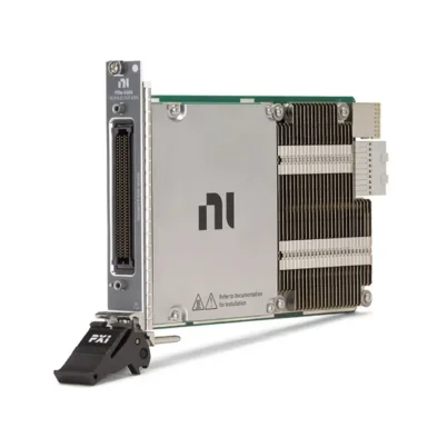
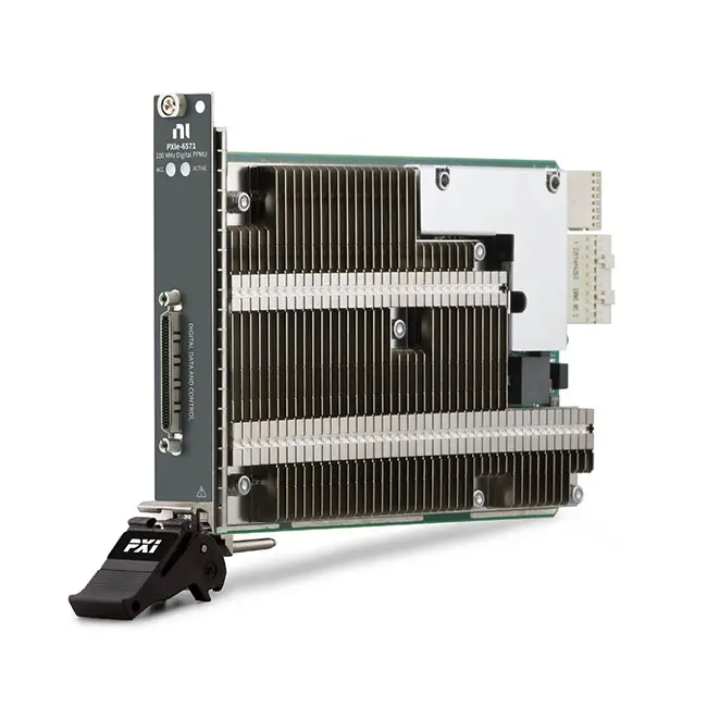
The PXIe‑6571 is a 100 MVector/s PXI Express digital pattern instrument designed for semiconductor validation, characterization and production testing. It is available in eight-channel and 32-channel configurations.
The PXIe‑6571 integrates digital pattern generation and comparison, per-pin timing, programmable voltage levels, active loads and per-pin parametric measurement units into a single-slot PXI Express module.
When used with the NI Digital Pattern Editor and NI-Digital Pattern Driver, engineers can configure pin maps, voltage levels, timing sets, pattern files, test specifications and semiconductor test flows within a unified software environment.
Product Overview
The National Instruments PXIe‑6571 belongs to the NI PXI Digital Pattern Instrument family.
The two main configurations are:
| Part Number | Configuration |
|---|---|
| 786320‑01 | 32-Channel PXIe‑6571 Digital Pattern Instrument |
| 786320‑02 | 8-Channel PXIe‑6571 Digital Pattern Instrument |
A typical semiconductor test architecture is:
Digital Pattern Editor / Test Program → PXIe‑6571 → Load Board / Interface → Semiconductor DUT
The instrument applies programmed digital levels and patterns to the DUT, compares returned pin states against expected values and records failures, captured data and parametric measurements.
Key Features
8-Channel or 32-Channel Configurations
The PXIe‑6571 is available with either eight or 32 digital test channels.
The 32-channel version is suitable for:
- Higher pin-count semiconductor devices
- Parallel digital interfaces
- Multi-site production test
- Mixed-signal IC validation
- RF front-end module testing
The eight-channel version is optimized for lower-channel-count benchtop characterization, laboratory validation and cost-sensitive test systems.
100 MVector/s Maximum Vector Rate
The PXIe‑6571 supports a maximum vector rate of 100 MVector/s, corresponding to a minimum vector period of 10 ns.
The vector architecture allows each test cycle to define:
- Pin drive states
- Expected compare states
- Timing set selection
- Pattern opcodes
- Source and capture behavior
- Sequencer operations
Up to 200 Mb/s Data Rate
The instrument supports data rates up to 200 Mb/s using supported timing and edge-multiplier configurations.
This capability is useful for testing digital interfaces that require more than one pin-state transition within a vector period.
Clock Generation up to 160 MHz
The PXIe‑6571 can generate clock signals at rates up to 160 MHz under supported timing configurations.
Clock rates above 133 MHz may use a non-50% duty cycle. The required duty cycle, edge placement and DUT timing specifications should be verified during test-program development.
Programmable Digital Voltage Levels
The digital pin electronics support voltage levels across a range of approximately −2 V to +6 V.
Programmable per-pin levels can include:
- Drive-high voltage
- Drive-low voltage
- Compare-high threshold
- Compare-low threshold
- Termination voltage
- Active-load commutation voltage
This flexibility allows one module to test devices using different logic families and supply voltages.
Per-Pin Parametric Measurement Units
Each digital channel includes a per-pin parametric measurement unit for DC characterization.
PPMU functions can include:
- Force voltage and measure current
- Force current and measure voltage
- Input leakage measurement
- Output voltage measurement
- Continuity testing
- Open and short detection
- Pin-current characterization
The documented PPMU measurement voltage range extends from approximately −2 V to +6 V, while supported force-voltage operation can extend to approximately +7 V.
16 mA Active Load
The PXIe‑6571 provides an active-load capability of up to 16 mA for supported semiconductor output testing.
Active loads can help validate DUT output behavior by applying a programmable current load and comparing the resulting pin voltage against defined thresholds.
Flexible Pattern Timing
The PXIe‑6571 provides programmable timing sets for defining when each pin drives data, returns to a level and compares DUT output states.
Timing features include:
- Up to 31 timing sets
- 39.0625 ps edge-placement resolution
- Per-pin edge timing
- Multiple drive formats
- Vector-by-vector timing-set selection
- Edge-multiplier support
Multiple Drive Formats
Supported digital drive formats include:
- Non-Return
- Return to Low
- Return to High
- Surround by Complement
The correct drive format depends on the DUT protocol, required pulse shape and timing definition.
Pattern Sequencing and Flow Control
The pattern sequencer supports opcodes and control structures for building reusable semiconductor test patterns.
Pattern execution can include:
- Loops
- Conditional jumps
- Subroutines
- Sequencer flags
- Sequencer registers
- Pattern labels
- Source and capture operations
- Test-program handshaking
Digital Pattern Editor
The PXIe‑6571 includes support for the NI Digital Pattern Editor, which provides an interactive environment for developing and debugging semiconductor digital tests.
The editor can be used to configure:
- Pin maps
- Pin groups
- Voltage levels
- Timing sets
- Test specifications
- Digital patterns
- Source waveforms
- Capture waveforms
Technical Specifications
| Parameter | Specification |
|---|---|
| Product Type | PXI Digital Pattern Instrument |
| Model | PXIe‑6571 |
| Part Numbers | 786320‑01 and 786320‑02 |
| Manufacturer | National Instruments |
| Bus Interface | PXI Express |
| Module Width | 1 Slot |
| Channel Configurations | 8 Channels or 32 Channels |
| Maximum Vector Rate | 100 MVector/s |
| Minimum Vector Period | 10 ns |
| Maximum Data Rate | 200 Mb/s |
| Maximum Clock Generation | 160 MHz |
| Digital Voltage Range | Approximately −2 V to +6 V |
| PPMU Measure Voltage Range | Approximately −2 V to +6 V |
| PPMU Force Voltage Range | Approximately −2 V to +7 V |
| Active Load | Up to 16 mA |
| Timing Sets | Up to 31 |
| Edge-Placement Resolution | 39.0625 ps |
| Drive Formats | NR, RL, RH and SBC |
| Pattern Sequencing | Flow Control, Loops, Subroutines, Flags and Registers |
| Debugging Tools | Shmoo, Digital Scope, History RAM and Pin-State Viewers |
| Software | NI-Digital Pattern Driver and Digital Pattern Editor |
| 32-Channel Cooling Requirement | 82 W Slot Cooling Capacity |
| 8-Channel Cooling Requirement | 58 W or 82 W Slot Cooling Capacity |
| Primary Applications | Semiconductor Validation, Characterization and Production Test |
How Does the PXIe‑6571 Work?
The PXIe‑6571 applies vector-based digital test patterns to a semiconductor DUT and evaluates the returned pin states.
A simplified test path is:
Digital Pattern → Timing and Level Resources → PXIe‑6571 Pin Electronics → DUT → Compare Results → Test Program
Each vector specifies the action for every active pin. A pin can drive logic high or low, compare the DUT response, remain inactive or participate in source and capture operations.
The pattern sequencer executes vectors according to the defined timing sets, opcodes, loops and subroutines. Failure information can be stored and analyzed through the software debugging tools.
Digital Pattern Testing
Digital pattern testing verifies whether a semiconductor device responds correctly to a defined sequence of digital inputs.
A typical pattern test includes:
- Configure the DUT pin map.
- Load the voltage-level file.
- Configure timing sets.
- Load or generate the digital pattern.
- Apply power to the DUT with suitable instruments.
- Burst the digital pattern.
- Compare actual DUT states with expected states.
- Review failure information.
- Record the test result.
Pin Maps and Pin Groups
A pin map associates semiconductor DUT pin names with PXIe‑6571 hardware channels.
Pin groups allow related pins to be addressed together, such as:
- Data buses
- Address buses
- Control pins
- Clock pins
- Serial interfaces
- Device-enable signals
A well-designed pin map makes pattern files easier to reuse across different fixtures, sites and test programs.
Voltage-Level Configuration
Level files define the electrical conditions used to drive and compare DUT pins.
Common level parameters include:
- Drive-high voltage
- Drive-low voltage
- Compare-high threshold
- Compare-low threshold
- Termination voltage
- Current limits
- Active-load settings
Voltage levels should always be verified against the DUT absolute maximum ratings and recommended operating conditions.
Pattern Timing Configuration
Timing sets define when each digital action occurs within a vector period.
Typical timing events include:
- Drive-on edge
- Drive-data edge
- Drive-return edge
- Compare-strobe edge
- Compare-strobe-open edge
- Compare-strobe-close edge
Multiple timing sets allow one pattern to test different interface speeds, timing margins and operating modes.
Per-Pin PPMU Measurements
The integrated PPMU allows DC parametric measurements to be performed on individual digital pins without requiring a separate source measure unit for every channel.
Typical PPMU tests include:
- Input leakage current
- Output-high voltage
- Output-low voltage
- Open and short detection
- Continuity testing
- Pin-clamp characterization
- Static current measurement
The PPMU does not replace a high-precision SMU when the application requires substantially higher voltage, current, accuracy or four-quadrant sourcing capability.
Active-Load Testing
The active load can apply current to a DUT output while the compare circuitry evaluates the resulting voltage.
This capability is useful for:
- VOH testing
- VOL testing
- Output-drive characterization
- Logic-threshold verification
- Semiconductor production screening
Source and Capture Functions
Source and capture functions allow test data to be supplied to or collected from selected DUT pins during pattern execution.
Source data can support:
- Serial data transmission
- Parallel data transmission
- Device-programming data
- Site-specific test information
- Variable payload generation
Capture functions can record:
- Serial DUT responses
- Parallel data buses
- Status registers
- Device identifiers
- Calculated result data
Pattern Sequencer Control
The PXIe‑6571 pattern sequencer provides flow-control functions that reduce the need to duplicate pattern vectors.
Sequencer features can be used for:
- Looping a pattern section
- Calling reusable subroutines
- Branching according to sequencer flags
- Passing numeric values through registers
- Handshaking with the test program
- Controlling variable pattern repetition
Semiconductor Validation
During validation, engineers can use the PXIe‑6571 to evaluate whether a new semiconductor design operates correctly across different voltage, timing and operating conditions.
Validation applications include:
- Functional digital testing
- Interface verification
- Register-access testing
- Protocol validation
- Timing-margin analysis
- Voltage-margin analysis
- Failure diagnosis
- Design-corner evaluation
Semiconductor Characterization
Characterization determines how DUT performance changes across voltage, timing, temperature and process conditions.
The PXIe‑6571 can support characterization through:
- Timing sweeps
- Voltage sweeps
- Shmoo testing
- Per-pin parametric measurements
- Repeated pattern testing
- Failure-history analysis
- Multi-condition test execution
Semiconductor Production Test
The PXIe‑6571 can be incorporated into automated semiconductor production systems that require repeatable digital functional and parametric testing.
A production test sequence may include:
- Initialize the PXI system and instrument session.
- Load pin maps, specifications, levels and timing files.
- Connect the DUT through the load board.
- Perform continuity and leakage tests.
- Apply DUT power.
- Burst functional digital patterns.
- Capture test and failure results.
- Perform parametric pin measurements.
- Assign pass/fail status or a test bin.
- Repeat the process for the next DUT or test site.
Multi-Site Testing
Multiple DUTs can be tested in parallel when the test-system channel count, load board and software architecture support multi-site operation.
Multi-site testing can improve production throughput by sharing:
- Pattern resources
- PXI chassis resources
- Power instruments
- System timing
- Handler or prober interfaces
- Test-program execution
The 32-channel PXIe‑6571 can be synchronized into larger digital subsystems with up to 512 channels when the required timing and chassis resources are provided.
Shmoo Testing
A Shmoo plot displays pass/fail behavior while two test conditions are swept across a defined range.
Common Shmoo variables include:
- Supply voltage versus frequency
- Drive voltage versus timing
- Compare threshold versus timing
- Temperature versus frequency
- Timing edge versus DUT voltage
Shmoo testing helps engineers identify operating margins and failure boundaries during characterization.
Digital Scope and Debugging Tools
The Digital Pattern Editor provides tools for inspecting instrument and DUT behavior during pattern development.
Debugging resources can include:
- Digital scope
- History RAM viewer
- Pin-state viewer
- System-status viewer
- Pattern breakpoint tools
- Failure analysis
- Shmoo plotting
These tools can help locate incorrect pin assignments, voltage levels, timing edges, expected states and pattern sequences.
WGL and STIL Pattern Conversion
The PXIe‑6571 natively uses NI digital pattern files with the .digipat format.
Industry-standard WGL and STIL files are not executed directly by the instrument. Compatible third-party conversion tools can convert supported WGL or STIL patterns into the NI digital pattern format.
Converted patterns should be verified for:
- Pin-state mapping
- Timing definitions
- Voltage specifications
- Pattern opcodes
- Scan data
- Cycle count
- Expected DUT responses
Mixed-Signal IC Testing
The PXIe‑6571 can be combined with other PXI instruments to test mixed-signal devices containing digital, analog and RF functions.
A mixed-signal system may include:
- PXIe‑6571 digital pattern instrument
- Source measure units
- Digital multimeters
- Oscilloscopes or digitizers
- Waveform generators
- RF vector signal transceivers
- PXI switching modules
- Timing and synchronization hardware
RF Front-End Module Testing
RF front-end modules often contain digital control interfaces in addition to RF signal paths.
The PXIe‑6571 can handle digital functions such as:
- Device configuration
- Register programming
- Mode control
- Status monitoring
- Functional digital testing
- MIPI-related testing when supported by the test implementation
RF generation and analysis require compatible PXI RF instruments in the same test system.
Cooling and Chassis Requirements
The PXIe‑6571 is a high-power, single-slot instrument. Chassis cooling capacity must be verified before installation.
The chassis requirements differ by version:
- The 32-channel PXIe‑6571 requires approximately 82 W of cooling capacity for the occupied slot.
- The eight-channel PXIe‑6571 can operate in a slot providing approximately 58 W or 82 W of cooling capacity.
The PXIe‑1095 is an appropriate chassis option for the 32-channel version because it provides the required high-power cooling architecture.
The PXIe‑1084 can be considered for the eight-channel version when its slot configuration and system cooling requirements are satisfied.
PXI System Requirements
The PXIe‑6571 cannot operate independently.
A complete system normally requires:
- PXIe‑6571 digital pattern instrument
- Compatible high-power PXI Express chassis
- Compatible PXI controller or remote-control connection
- Suitable digital test cable and load board
- DUT power and measurement instruments
- NI-Digital Pattern Driver
- NI Digital Pattern Editor
- Application-specific pin maps, levels, timing and pattern files
Load Board and Cabling Considerations
The interface between the PXIe‑6571 and the DUT can significantly affect digital test performance.
Before designing or selecting a load board, consider:
- Connector compatibility
- Controlled-impedance routing
- Trace length
- Channel-to-channel skew
- Ground-return paths
- Signal integrity
- DUT power distribution
- Decoupling
- Relay and switching resources
- Protection against overvoltage and electrostatic discharge
System Integration Considerations
Before selecting the PXIe‑6571, verify:
- Required number of digital channels
- Eight-channel or 32-channel part number
- DUT voltage range
- Maximum pattern and data rate
- Required clock frequency
- PPMU voltage and current requirements
- Active-load requirements
- Pattern memory requirements
- Multi-site requirements
- Load-board and cable design
- Chassis slot cooling capacity
- PXI controller performance
- NI-Digital software compatibility
Troubleshooting PXIe‑6571 Systems
If a PXIe‑6571 test does not execute correctly, check the hardware, software and test-program configuration.
- Verify that the PXIe‑6571 is detected by the PXI controller.
- Confirm that the chassis slot provides sufficient cooling.
- Verify the installed NI-Digital Pattern Driver version.
- Confirm that the correct eight-channel or 32-channel configuration is selected.
- Check the pin map and channel assignments.
- Verify DUT voltage levels and current limits.
- Check timing-set periods and edge placement.
- Confirm the pattern file and label name.
- Review pattern compilation errors.
- Inspect load-board connections and signal integrity.
- Use digital scope and history RAM to locate failures.
- Verify trigger and synchronization configuration.
- Confirm that DUT power is applied in the correct sequence.
How to Choose a PXI Digital Pattern Instrument
Before purchasing a digital pattern instrument, determine:
- Required channel count
- Required vector rate
- Required maximum data rate
- Required clock-generation rate
- DUT voltage range
- PPMU measurement requirements
- Active-load current
- Timing-set and edge-placement requirements
- Pattern memory depth
- Multi-site channel requirements
- Chassis power and cooling capacity
- Software and pattern-format requirements
Industries
- Semiconductor Manufacturing
- Semiconductor Design Validation
- Mixed-Signal IC Testing
- RF Front-End Module Testing
- Automotive Semiconductor Test
- Consumer Electronics
- Aerospace and Defense Electronics
- Research and Development
- Automated Test Equipment
Applications
Semiconductor Functional Test
The PXIe‑6571 can apply digital stimulus patterns and compare DUT responses against expected pin states.
DC Parametric Measurement
Integrated per-pin PPMUs support continuity, leakage, output-voltage and other static pin measurements.
Timing Characterization
Programmable timing sets and edge placement allow engineers to evaluate DUT timing margins and operating limits.
Shmoo Testing
Voltage, frequency and timing conditions can be swept to visualize semiconductor pass/fail operating regions.
Multi-Site Production Test
Multiple instruments and DUT sites can be synchronized to increase semiconductor production throughput.
Mixed-Signal IC Test
The PXIe‑6571 can be integrated with PXI analog, RF, power and switching modules to test complex mixed-signal devices.
PXIe‑6571 vs PXIe‑6570
| Feature | PXIe‑6571 | PXIe‑6570 |
|---|---|---|
| Channel Configurations | 8 or 32 Channels | 32 Channels |
| Maximum Vector Rate | 100 MVector/s | 100 MVector/s |
| Maximum Data Rate | 200 Mb/s | 200 Mb/s |
| Module Width | 1 Slot | 2 Slots |
| Active Load | 16 mA | 24 mA |
| Channel Density | Higher | Lower |
| Best For | High-Density or Low-Channel-Count Configurations | Applications Requiring Higher Active-Load Capability |
The PXIe‑6571 provides higher single-slot channel density and offers an eight-channel configuration. The PXIe‑6570 occupies two slots but provides a higher active-load capability.
PXIe‑6571 vs PXIe‑6556
| Feature | PXIe‑6571 | PXIe‑6556 |
|---|---|---|
| Instrument Type | Digital Pattern Instrument | High-Speed Digital Waveform Generator/Analyzer |
| Primary Application | Semiconductor Pattern Test | Digital Interface and Waveform Test |
| Per-Pin PPMU | Integrated | Different Parametric Architecture |
| Pattern Sequencer | Semiconductor-Oriented | Waveform-Oriented |
| Digital Pattern Editor | Supported | Uses NI-HSDIO Workflow |
| Best For | IC Validation and Production Test | High-Speed Digital Protocol and Waveform Testing |
Recommended Related Products
| PXIe‑6570 | 32-channel PXI digital pattern instrument with 100 MVector/s operation and 24 mA active-load capability. |
| PXIe‑6556 | High-speed digital waveform generator/analyzer for digital interface and electronic validation applications. |
| PXIe‑1095 | High-power PXI Express chassis suitable for the cooling requirements of the 32-channel PXIe‑6571. |
| PXIe‑1084 | PXI Express chassis option for the eight-channel PXIe‑6571 when slot cooling requirements are satisfied. |
| PXIe‑8880 | High-performance PXI Express embedded controller for demanding automated semiconductor test systems. |
| PXIe‑4140 | Four-channel source measure unit for semiconductor power supply and DC parametric measurements. |
| NI PXI Modules | Modular digital, analog, RF, power and switching instruments for automated semiconductor test systems. |
Why Choose PXIe‑6571?
- Eight-channel or 32-channel configurations
- Single-slot PXI Express form factor
- Maximum vector rate of 100 MVector/s
- Data rates up to 200 Mb/s
- Clock generation up to 160 MHz
- Programmable digital voltage levels
- Integrated per-pin PPMUs
- 16 mA active-load capability
- Up to 31 timing sets
- 39.0625 ps edge-placement resolution
- Multiple digital drive formats
- Pattern sequencing and flow control
- Source and capture functions
- Digital Pattern Editor integration
- Shmoo and digital scope tools
- Suitable for semiconductor validation
- Suitable for characterization
- Suitable for multi-site production test
- Suitable for mixed-signal IC testing
Frequently Asked Questions
What is the PXIe‑6571?
The PXIe‑6571 is an eight-channel or 32-channel, 100 MVector/s PXI Express digital pattern instrument for semiconductor validation, characterization and production testing.
What are the PXIe‑6571 part numbers?
The 32-channel PXIe‑6571 is commonly identified by part number 786320‑01, while the eight-channel version is identified by part number 786320‑02.
What is the maximum PXIe‑6571 vector rate?
The maximum vector rate is 100 MVector/s, corresponding to a minimum vector period of 10 ns.
What is the maximum data rate?
The PXIe‑6571 supports data rates up to 200 Mb/s through supported edge-multiplier configurations.
How many channels does the PXIe‑6571 provide?
The module is available with either eight or 32 digital test channels.
Does the PXIe‑6571 include a PPMU?
Yes. Each digital test channel includes per-pin parametric measurement capability for force-voltage, force-current and related DC measurements.
What voltage range does the PXIe‑6571 support?
Its digital pin electronics support approximately −2 V to +6 V. PPMU force-voltage operation can extend to approximately +7 V under supported conditions.
Can the PXIe‑6571 perform continuity and leakage tests?
Yes. The integrated per-pin PPMUs can support continuity, input leakage and other static pin measurements.
Does the PXIe‑6571 support Shmoo testing?
Yes. The Digital Pattern Editor includes Shmoo tools for sweeping voltage, timing and other test conditions.
Can the PXIe‑6571 read WGL or STIL files directly?
No. It natively uses NI .digipat files. Compatible conversion tools can convert supported WGL and STIL patterns into the NI digital pattern format.
Can multiple PXIe‑6571 modules be synchronized?
Yes. Multiple instruments can be synchronized into larger digital subsystems when the required chassis, timing and software resources are provided.
Which chassis is recommended for the 32-channel PXIe‑6571?
The 32-channel version requires a slot with approximately 82 W cooling capacity. The PXIe‑1095 is a suitable high-power chassis option.
Can the eight-channel PXIe‑6571 use a PXIe‑1084 chassis?
Yes. The eight-channel version can operate in a chassis slot providing approximately 58 W of cooling, such as an appropriately configured PXIe‑1084.
Does the PXIe‑6571 operate independently?
No. It requires a compatible PXI Express chassis, PXI controller or remote host, NI-Digital software, cabling and a suitable DUT interface or load board.
What software does the PXIe‑6571 use?
The module uses the NI-Digital Pattern Driver and NI Digital Pattern Editor for test development, hardware control and debugging.
What is the difference between PXIe‑6571 and PXIe‑6570?
The PXIe‑6571 occupies one slot and is available with eight or 32 channels. The PXIe‑6570 occupies two slots and provides a higher active-load capability.
What should I check before purchasing a PXIe‑6571?
Verify the required channel count, exact part number, DUT voltage, vector rate, PPMU requirements, load-board interface, multi-site architecture, software compatibility and chassis cooling capacity.
Conclusion
The PXIe‑6571 100 MVector/s PXI Digital Pattern Instrument combines high-density digital pin electronics, per-pin PPMUs, programmable timing, pattern sequencing and semiconductor debugging tools in a single-slot PXI Express module. Its eight-channel and 32-channel configurations make it suitable for benchtop characterization, design validation, mixed-signal IC testing and multi-site semiconductor production systems.















