






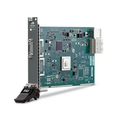
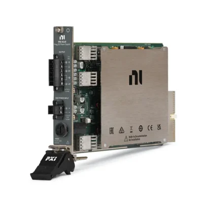

The PXIe-4112 is a two-channel programmable DC power supply for PXI Express systems. Each isolated channel can provide up to 60 V, 1 A and 60 W, delivering a total output power of 120 W when the required auxiliary power source is connected.
Designed for automated validation and production testing, the PXIe-4112 combines programmable voltage and current limits, simultaneous voltage and current readback, four-wire remote sensing, output disconnect relays and hardware triggering in a single-slot PXI Express module.
Key Features of the PXIe-4112
- Two programmable DC power supply channels
- 0.1 V to 60 V programmable voltage range
- Up to 1 A output current per channel
- 60 W maximum output power per channel
- 120 W total output power
- Channel-to-channel and channel-to-ground isolation
- Simultaneous voltage and current measurement
- Maximum measurement rate of 5,250 samples/s
- Four-wire remote sensing
- Output disconnect relays
- Low output ripple and noise
- PXI hardware triggering and sequencing
- Overcurrent, reverse-voltage and overtemperature protection
- Single-slot 3U PXI Express form factor
PXIe-4112 Technical Specifications
| Product Model | PXIe-4112 |
|---|---|
| Product Type | PXI Programmable DC Power Supply |
| Number of Channels | 2 |
| Operating Quadrant | Single quadrant, source only |
| Voltage Range | 0.1 V to 60 V |
| Maximum Current | 1 A per channel |
| Output Power | 60 W per channel |
| Total Output Power | 120 W |
| Minimum Programmable Voltage | 0.1 V |
| Minimum Programmable Current Limit | 0.01 A |
| Voltage Programming Resolution | 2 mV |
| Current Programming Resolution | 34 µA |
| Voltage Measurement Resolution | 17 mV |
| Current Measurement Resolution | 274 µA |
| Maximum Measurement Rate | 5,250 measurements/s, nominal |
| Voltage Ripple and Noise | Less than 24 mV peak-to-peak; less than 4 mV RMS, typical |
| Current Noise | Less than 2 mA RMS, typical |
| Remote Sense | Four-wire sensing, up to 1 V lead drop per output lead |
| Isolation | Channel-to-channel and channel-to-ground |
| Continuous Isolation Voltage | 150 VDC, CAT I |
| Withstand Voltage | 1,000 VRMS |
| Output Connector | 10-position Phoenix Contact screw terminal |
| Auxiliary Power Requirement | 45.6 VDC to 50.4 VDC, 3.5 A maximum |
| Form Factor | 3U, single-slot PXI Express module |
| Dimensions | 2.0 cm × 13.0 cm × 21.6 cm |
| Weight | 443 g, nominal |
| Recommended Calibration Interval | 2 years |
| Operating Temperature | 0°C to 55°C |
| Storage Temperature | -40°C to 70°C |
| Operating Humidity | 10% to 90%, noncondensing |
PXIe-4112 Part Numbers and Configurations
| Part Number | Configuration | Auxiliary Power Source |
|---|---|---|
| 782857-01 | PXIe-4112 programmable power supply package | Included |
| 782956-01 | PXIe-4112 module without auxiliary power supply | Not included |
Both configurations provide the same two-channel, 60 V, 1 A power supply functionality. The difference is whether the PXIe-411x auxiliary power source is included with the order.
Two Isolated 60 W Output Channels
The PXIe-4112 provides two identical power supply channels, with each channel capable of sourcing up to 60 V, 1 A and 60 W. The channels are isolated from one another and from the PXI chassis ground.
This isolation allows engineers to power separate circuits with reduced ground interaction. The channels may also be used in suitable series or floating configurations, provided that all terminal voltages remain within the specified isolation limits.
Programmable Voltage and Current Limits
Engineers can independently program the voltage level and current limit for each channel. The module operates as a constant-voltage source until the connected load attempts to draw more than the programmed current limit.
Current limiting helps protect prototypes, electronic assemblies and components during automated testing. The minimum programmable voltage level is 0.1 V, while the minimum programmable current limit is 0.01 A.
Voltage and Current Readback
The PXIe-4112 can measure output voltage and current while supplying power to the device under test. This readback functionality allows the test system to verify that the expected voltage reaches the load and monitor current consumption during different operating states.
Measurement data can be recorded alongside results from digital multimeters, oscilloscopes, DAQ modules and other PXI instruments to create a complete power and functional test record.
Maximum 5,250 Samples/s Measurement Rate
The module supports a maximum nominal measurement rate of 5,250 samples per second. This allows automated applications to monitor changes in voltage and current during device startup, operating-mode transitions and test sequences.
The selected measurement aperture, line-frequency setting and averaging configuration affect measurement rate, accuracy and noise rejection.
Four-Wire Remote Sense
Four-wire remote sensing compensates for voltage lost across the cables between the power supply and the device under test. Separate sense connections measure voltage directly at the load, allowing the module to adjust its output accordingly.
The PXIe-4112 can compensate for up to 1 V of output lead drop per lead, with a maximum sense-lead resistance of 1 Ω per lead. Remote sensing is particularly useful when high current or long cables produce a measurable voltage drop.
Output Disconnect Relays
Integrated output disconnect relays separate the output channels from the device under test when the outputs are disabled. This provides a more complete disconnection than simply programming the voltage to its minimum level.
Output disconnection is useful in automated test systems that must safely connect, power, test and remove multiple devices without manually rewiring the power supply.
Output Ripple and Noise
The PXIe-4112 has typical voltage ripple and noise below 24 mV peak-to-peak and 4 mV RMS. Typical current noise is below 2 mA RMS under the specified measurement conditions.
Actual noise at the device under test can also be affected by grounding, cable routing, remote-sense wiring, load characteristics and electromagnetic interference from other equipment.
Protection Features
- Programmable current limiting
- Reverse-voltage clamp protection
- Thermal overload protection
- Automatic shutdown during overtemperature conditions
- Fused auxiliary power input
- Auxiliary input overvoltage shutdown
- Output disconnect relays
The PXIe-4112 is intended for CAT I circuits and must not be connected directly to AC mains or CAT II, CAT III or CAT IV measurement environments.
Hardware Timing and Triggering
The PXIe-4112 supports start, source, sequence-advance and measurement triggers. Trigger signals can be received from or exported to PXI trigger lines 0 through 7.
Hardware triggering allows the power supply to coordinate voltage changes and measurements with other PXI instruments, including switches, digital modules, digitizers and data acquisition devices.
Typical Applications
- Automated electronic device testing
- Automotive electronic control unit testing
- Aerospace and defense system validation
- Component characterization
- Printed circuit board functional testing
- Power consumption measurement
- Device startup and shutdown testing
- Production-line test systems
- Battery-powered device simulation
- Research and laboratory power control
NI-DCPower Software Support
The PXIe-4112 is controlled using the NI-DCPower instrument driver. NI-DCPower provides functions for configuring voltage levels, current limits, measurements, triggering, sequencing and output states.
The module can be used with LabVIEW, LabWindows/CVI, supported .NET environments and other compatible development tools. InstrumentStudio provides an interactive environment for configuring outputs, monitoring measurements and testing the module without developing a complete application.
PXI Express System Integration
The PXIe-4112 occupies one PXI Express or compatible CompactPCI Express slot. Its compact format allows programmable power to be integrated with other test instruments in the same PXI chassis.
Before ordering, verify the chassis slot type, cooling capacity, controller compatibility, NI-DCPower version, terminal accessories and auxiliary power requirements.
Auxiliary Power Requirements
The module requires an external auxiliary power source to deliver its full 120 W output capability. The auxiliary input requires between 45.6 VDC and 50.4 VDC and can draw up to 3.5 A.
Part number 782857-01 includes the PXIe-411x auxiliary power source. Part number 782956-01 does not include it and is intended for systems that already have a compatible auxiliary power solution.
PXIe-4112 Connection Guidance
- Power off the chassis before installing the module.
- Use the supplied screw-terminal connector kit.
- Confirm the polarity of every output and sense connection.
- Keep remote-sense wiring close to the corresponding output wiring.
- Use wire between 12 AWG and 24 AWG as permitted by the connector.
- Verify that the auxiliary power source is correctly connected.
- Set a safe current limit before enabling the output.
- Do not exceed the channel isolation ratings.
PXIe-4112 Troubleshooting
The module cannot reach the programmed voltage
Check whether the channel has entered current-limit operation. Verify the connected load, programmed current limit, cable resistance and auxiliary power connection.
The output power is limited
Confirm that a compatible PXIe-411x auxiliary power source is connected. Chassis power alone is not sufficient for full 60 W operation on each channel.
The voltage at the load is lower than expected
Measure the voltage drop across the output cables and use four-wire remote sensing when appropriate. Verify that the sense wires are connected directly to the device-under-test terminals.
The voltage reading is unstable or noisy
Check grounding, cable routing, sense-wire connections, averaging settings and nearby switching equipment. Allow the recommended warm-up time before performing accuracy-sensitive measurements.
The output shuts down unexpectedly
Check for overtemperature, reverse voltage, excessive current or an auxiliary input fault. Ensure that the PXI chassis fans operate at the required speed and that airflow is unobstructed.
The output remains disconnected
Verify the NI-DCPower output-enabled setting, output disconnect configuration, active protection conditions and test sequence state.
PXIe-4112 Compared with Related Power Modules
| Model | Channels | Maximum Voltage | Maximum Current | Recommended Use |
|---|---|---|---|---|
| PXIe-4112 | 2 | 60 V | 1 A | Higher-voltage isolated DC power |
| PXIe-4113 | 2 | 10 V | 6 A | Lower-voltage, higher-current devices |
| PXI-4110 | 3 | 20 V | 1 A | General-purpose multirail power applications |
| PXIe-4141 | 4 | ±10 V | ±100 mA | Precision four-quadrant source and measurement |
Recommended Related Products
- NI PXIe-4113 Programmable Power Supply – Provides two isolated 10 V, 6 A channels for lower-voltage, higher-current devices.
- NI PXI-4110 Triple-Output Power Supply – A three-channel option for general-purpose and multirail device testing.
- NI PXIe-4141 Precision Source Measure Unit – Recommended when four-quadrant operation and more sensitive current measurements are required.
- NI PXIe-4080 Digital Multimeter – Adds independent precision voltage, current and resistance measurements to a power test system.
How to Select the Correct PXI Power Supply
Choose the PXIe-4112 when the application requires up to 60 V and 1 A from each of two isolated channels. It is particularly suitable for powering higher-voltage electronics while monitoring voltage and current consumption.
Select the PXIe-4113 when the device requires more current but no more than 10 V. Choose a source measure unit when the application requires four-quadrant operation, current sinking or substantially higher measurement sensitivity.
Why Choose the PXIe-4112?
- Provides two isolated 60 W channels
- Combines power sourcing and output readback
- Compensates for cable loss with remote sensing
- Disconnects the DUT using integrated relays
- Supports hardware-timed automated sequences
- Integrates with other PXI measurement instruments
- Offers two configurations with or without auxiliary power
Frequently Asked Questions
What is the PXIe-4112 used for?
The PXIe-4112 supplies programmable DC power and measures output voltage and current in automated electronic testing systems.
How many channels does the PXIe-4112 provide?
It provides two independently programmable and isolated output channels.
What are the maximum voltage and current?
Each channel can supply up to 60 V, 1 A and 60 W.
Can the PXIe-4112 sink current?
No. It is a single-quadrant power supply designed to source voltage and current. Choose a four-quadrant SMU when controlled current sinking is required.
Does it measure voltage and current?
Yes. It provides simultaneous voltage and current readback while powering the device under test.
Does it support remote sensing?
Yes. Each channel supports four-wire remote sensing to compensate for output cable voltage drop.
Is an auxiliary power supply required?
Yes. A compatible auxiliary power source is required for full output capability. Part number 782857-01 includes it, while 782956-01 does not.
What software controls the module?
The PXIe-4112 is controlled with NI-DCPower and can be used interactively through InstrumentStudio or programmed in supported development environments.
What is the recommended calibration interval?
NI specifies a recommended calibration interval of two years.
Request a Quote for the PXIe-4112
Contact us for current availability, lead time and project pricing for the PXIe-4112 Two-Channel Programmable DC Power Supply. We can also help identify the correct part number, auxiliary power source, terminal accessories, PXI chassis and related measurement modules.















