






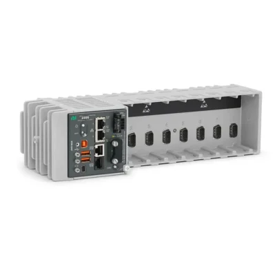


PXI-2586 10-Channel High-Power SPST Relay Module
The PXI-2586 is a general-purpose PXI relay module with 10 independently controlled, normally open SPST Form A electromechanical relays. It is designed for switching high-current and high-voltage power signals in automated test and control systems.
Each channel supports switching and carrying currents up to 12 A and voltages up to 300 V. With software-controlled routing, low initial path resistance and a 20 MHz bandwidth, the PXI-2586 is suitable for battery testing, power supply validation, automotive electronics and industrial load control.
Key Features of the PXI-2586
- 10 independent SPST Form A relay channels
- Alternative 5-DPST topology
- Normally open, nonlatching relay operation
- Maximum switching and carry current of 12 A
- Maximum switching voltage of 300 V
- 300 V CAT II channel-to-ground rating
- Maximum AC switching power of 3 kVA per channel
- 20 MHz typical switch bandwidth
- 50 mΩ initial DC path resistance
- 65-cycle-per-second scan rate
- 15.4 ms maximum relay operate time
- Relay usage tracking for preventive maintenance
- PXI trigger line support
- Field-replaceable electromechanical relays
- Single-slot 3U PXI module
PXI-2586 Technical Specifications
| Product Model | PXI-2586 |
|---|---|
| Part Number | 778572-86 |
| Product Type | High-Power PXI Relay Module |
| Primary Topology | 10-SPST |
| Alternative Topology | 5-DPST |
| Relay Configuration | SPST Form A, normally open |
| Number of Independent Channels | 10 |
| Maximum Switching Current | 12 A per channel at ambient temperatures up to 45°C |
| Maximum Carry Current | 12 A per channel |
| Maximum Switching Voltage | 300 V |
| Channel-to-Ground Rating | 300 V CAT II |
| Maximum AC Switching Power | 3 kVA per channel, up to 60 Hz |
| Maximum Channels at 12 A | 2 simultaneously |
| Initial DC Path Resistance | 50 mΩ |
| Minimum Switching Load | 12 V or 100 mA |
| Switch Bandwidth | 20 MHz |
| Scan Rate | 65 cycles/s |
| Maximum Relay Operate Time | 15.4 ms |
| Mechanical Relay Life | 1 × 10⁷ operations |
| Relay Contact Material | Silver-nickel |
| I/O Connector | 20-position Positronic GMCT series plug |
| Bus Connection | PXI Hybrid compatible |
| Module Size | 3U, single slot |
| Operating Temperature | 0°C to 55°C, with current derating above 45°C |
Part Number and Configuration
| Part Number | Topology | Maximum Current | Maximum Voltage | Bandwidth |
|---|---|---|---|---|
| 778572-86 | 10-SPST or 5-DPST | 12 A | 300 V | 20 MHz |
Independent SPST Relay Operation
The standard PXI-2586 topology provides 10 independently controlled SPST Form A relays. Each channel operates as a normally open switch that closes when activated through software.
Independent relay control allows the module to connect or disconnect multiple loads, power rails, test points and external devices. The channels are not internally connected as a multiplexer, giving engineers flexibility when building custom switching systems.
Alternative 5-DPST Configuration
The PXI-2586 can also be configured as five double-pole, single-throw switching paths. In this topology, two relays are operated together to switch both conductors of a circuit.
The 5-DPST configuration is useful when the application must disconnect both sides of a load or switch paired conductors simultaneously. The correct topology should be selected in NI-SWITCH before creating routes.
High-Current and High-Voltage Switching
The PXI-2586 supports switching and carrying currents up to 12 A per channel at ambient temperatures of 45°C or below. It also supports switching voltages up to 300 V with a 300 V CAT II channel-to-ground rating.
The 12 A and 300 V ratings are individual limits and do not mean the module can switch 12 A at 300 V under every condition. Maximum DC switching current decreases as the DC voltage increases, and the application must remain within the specified DC load curve.
Module Load Derating
A maximum of two channels can carry 12 A simultaneously. When multiple channels carry current, the combined module load must satisfy the PXI-2586 derating requirement:
Sum of the squared currents for all active channels must not exceed 400 A²-channels.
The maximum current must also be reduced when the ambient temperature exceeds 45°C. Engineers should verify both the per-channel switching curve and total module load before connecting multiple high-current circuits.
Switching Inductive Loads
Motors, relays, solenoids and other inductive loads can produce high-voltage transients when the current is interrupted. These transients can exceed the PXI-2586 voltage rating, shorten relay life or interfere with system operation.
Use appropriate flyback diodes, snubber networks, transient voltage suppressors or other protection devices selected for the connected load. Protective components should be installed close to the inductive device whenever practical.
Relay Life and Preventive Maintenance
The PXI-2586 electromechanical relays have an expected mechanical life of up to 10 million operations under specified conditions. Electrical life depends on the switched voltage, current, load type, switching frequency and transient suppression.
The module tracks relay operation counts, allowing maintenance software to identify heavily used channels. Relay count monitoring can help reduce unexpected downtime in production and validation systems.
The individual relays are field replaceable. Replacement should be performed according to the applicable NI service instructions and electrical safety procedures.
Triggering and Automated Scanning
The PXI-2586 supports input and output triggering through PXI trigger lines 0 through 7. Hardware triggering allows relay operations to be coordinated with digital multimeters, power supplies, source measure units and other PXI instruments.
Automated scanning can execute a predefined sequence of relay connections without requiring individual host commands for every operation. This improves repeatability and throughput in automated test systems.
Typical PXI-2586 Applications
- Battery pack and battery management system testing
- Power supply validation
- Automotive electrical testing
- Industrial load switching
- Motor and solenoid control
- Power distribution testing
- Device power cycling
- Electronic control unit validation
- High-current continuity testing
- Automated production testing
- Fault insertion systems
- Laboratory power routing
Software and Driver Support
The PXI-2586 is controlled using the NI-SWITCH driver. NI-SWITCH provides relay control, topology configuration, scan-list execution, triggering and relay-count monitoring.
NI Switch Executive can simplify the configuration and management of larger switching systems by allowing engineers to create channel aliases, define routes and detect routing conflicts. The module can also be controlled from LabVIEW, LabWindows/CVI, C/C++, C# and supported Python environments.
Cables and Connector Requirements
The PXI-2586 uses a 20-position Positronic GMCT series front connector. A compatible connector and backshell kit can be used to build an application-specific high-current cable assembly.
Appropriate conductor size, insulation voltage, shielding, strain relief and connector assembly procedures are essential. High-current applications commonly require 16 AWG stranded conductors or another wire size selected according to the applicable current, temperature and regulatory requirements.
When hazardous voltage is present on any relay terminal, do not connect safety extra-low-voltage signals to another relay terminal on the same module.
PXI Chassis and System Integration
The PXI-2586 is a single-slot 3U module designed for compatible PXI and PXI hybrid systems. Verify the chassis slot type, power capacity and airflow before installation.
Compatible chassis options include the PXIe-1092, PXIe-1085 and other chassis offering a suitable hybrid-compatible peripheral slot.
Installation and Troubleshooting
Module Is Not Detected
Confirm that the PXI-2586 is fully installed in a compatible PXI or hybrid slot. Verify chassis operation, controller communication and NI-SWITCH driver installation before refreshing the system in NI Measurement & Automation Explorer.
Relay Closes but the Load Does Not Operate
Check the external wiring, connector pinout, power source and load. Measure the complete path resistance and confirm that the load current does not exceed the applicable switching curve.
Relay Operation Is Intermittent
Inspect the connector and cable assembly for loose contacts, damaged conductors or insufficient strain relief. Review the relay count and path resistance to determine whether the relay is approaching the end of its electrical life.
Relay Life Is Shorter Than Expected
Confirm that voltage, current and switching power remain within the specified limits. Inductive, capacitive and lamp loads can produce high inrush current or transient voltage and may require protection or additional derating.
Module Becomes Too Warm
Review the number of simultaneously active channels and calculate the combined squared-current load. Reduce channel current when the chassis ambient temperature exceeds 45°C and confirm that chassis airflow is not obstructed.
PXI-2586 Comparison with Similar PXI Switch Modules
| Model | Topology | Recommended Selection |
|---|---|---|
| PXI-2586 | 10 independent SPST or 5-DPST relays | Independent high-current and high-voltage load switching |
| PXI-2585 | 10×1 high-power multiplexer | Routing multiple high-power inputs to one common connection |
| PXI-2567 | High-channel-count independent relay switching | Applications requiring more channels at lower power |
| PXI-2569 | General-purpose SPST relay switching | High-channel-count control and signal routing |
| PXI-2530B | Configurable multiplexer and matrix switching | Flexible low-power signal routing and scanning |
Recommended Related Products
- PXI-2585 High-Power Multiplexer – provides a 10×1 topology for routing high-power signals to a common connection
- PXI-2567 Relay Module – suitable for systems requiring more independently controlled relay channels
- PXI-2569 SPST Relay Module – provides general-purpose, high-channel-count relay switching
- PXI-2530B Multiplexer/Matrix Switch – supports configurable signal-routing topologies
- PXIe-1092 PXI Express Chassis – provides hybrid-compatible slots for modular switching and measurement systems
Additional compatible switching hardware is available in our NI PXI modules category.
How to Select the PXI-2586
Choose the PXI-2586 when an application requires up to 10 independently controlled relay channels for high-current or high-voltage loads. It is appropriate when an SPST or DPST topology is needed rather than a multiplexer that connects several inputs to one common terminal.
Before purchasing, calculate the maximum voltage, current, switching power, inrush current and combined module load. Also confirm the load type, required transient suppression, cable assembly, connector kit and chassis compatibility.
Why Choose the PXI-2586?
The PXI-2586 combines 12 A switching capability, a 300 V rating and independent software-controlled relays in a compact PXI module. Its trigger support, relay monitoring and alternative SPST or DPST configurations make it suitable for reliable automated power switching.
Frequently Asked Questions
How many relays does the PXI-2586 provide?
The PXI-2586 provides 10 independent SPST Form A relays. It can also be configured as five DPST switching paths.
What is the maximum switching current?
The maximum switching and carry current is 12 A per channel at ambient temperatures up to 45°C. A maximum of two channels can simultaneously operate at the full 12 A rating.
What is the maximum switching voltage?
The PXI-2586 supports switching voltages up to 300 V and has a 300 V CAT II channel-to-ground rating.
Can the PXI-2586 switch 12 A at 300 VDC?
Not necessarily. The current and voltage specifications are separate maximum limits. The allowable DC current decreases as switching voltage increases and must be determined from the official DC switching-power curve.
What is the difference between the PXI-2585 and PXI-2586?
The PXI-2585 is configured as a 10×1 high-power multiplexer, while the PXI-2586 provides 10 independent SPST relays or five DPST switching paths.
Are the PXI-2586 relays replaceable?
Yes. The electromechanical relays are field replaceable according to the applicable NI service procedure.
What is the part number for the PXI-2586?
The standard NI part number for the PXI-2586 is 778572-86.
Request a Quote for the PXI-2586
Contact us for current availability, lead time and project pricing for the PXI-2586 10-Channel High-Power Relay Module. We can also help identify compatible connector kits, cables, PXI chassis and related switching modules for your automated test system.















