






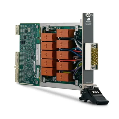

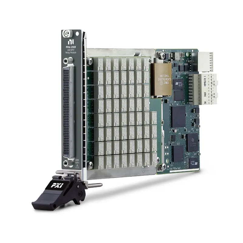
PXIe-2569 100-Channel 1 A SPST PXI Express Relay Module
The PXIe-2569 is a high-density, general-purpose PXI Express relay module designed for automated test equipment, programmable load control and signal routing. It provides 100 independent single-pole single-throw Form A relay channels in a single PXI Express slot.
Each channel uses a latching electromechanical armature relay capable of switching or carrying up to 1 A. With 100 V operation, at least 20 MHz typical bandwidth and a 32,000-step onboard scan list, the PXIe-2569 is suitable for deterministic switching of medium-power ATE loads and instrumentation signals.
Key Features of the PXIe-2569
- 100 independent SPST Form A relay channels
- Alternative 50-channel DPST topology
- 1 A maximum switching or carry current per channel
- 100 V maximum channel-to-channel switching voltage
- 100 V maximum channel-to-ground voltage, CAT I
- 60 W or 62.5 VA maximum switching power per channel
- 20 MHz or greater typical bandwidth
- Less than 0.55 Ω initial DC path resistance
- Less than 12 µV typical thermal EMF
- Latching electromechanical armature relays
- 145 cycles/s scan rate
- 32,000-step onboard scan list
- 1 ms typical relay operating time
- PXI hardware trigger support
- Field-replaceable relays
- 200-position LFH front connector
- Single-slot PXI Express module
- NI-SWITCH and NI Switch Executive support
PXIe-2569 Technical Specifications
| Product Model | PXIe-2569 |
|---|---|
| Part Number | 780587-69 |
| Product Type | High-density PXI Express relay module |
| Default Topology | 100-SPST, Form A |
| Alternative Topology | 50-DPST |
| Number of Relays | 100 |
| Relay Type | Electromechanical armature relay |
| Relay Operation | Latching |
| Maximum Switching Voltage | 100 V channel-to-channel |
| Maximum Channel-to-Ground Voltage | 100 V, CAT I |
| Maximum Switching or Carry Current | 1 A per channel |
| Maximum Switching Power | 60 W or 62.5 VA per channel |
| Maximum Simultaneous 1 A Channels | 50 channels at 35°C or lower |
| Minimum Switch Load | 20 mV, 10 mA |
| Initial DC Path Resistance | Less than 0.55 Ω |
| End-of-Life Path Resistance | 1 Ω or greater |
| Thermal EMF | Less than 12 µV, typical |
| Bandwidth | 20 MHz or greater, typical |
| Scan Rate | 145 cycles/s |
| Onboard Scan List | Up to 32,000 steps |
| Typical Relay Operate Time | 1 ms |
| Maximum Relay Operate Time | 3.4 ms |
| Mechanical Relay Life | 1 × 10⁸ cycles |
| Input Trigger Sources | PXI trigger lines 0 through 7 |
| Minimum Input Trigger Pulse Width | 150 ns with digital filtering enabled |
| Output Trigger Destinations | PXI trigger lines 0 through 7 |
| Output Trigger Pulse Width | Programmable from 1 µs to 62 µs |
| Front-Panel Connector | 200-position LFH Matrix 50 receptacle |
| Bus Interface | PXI Express |
| PXI Express Power Requirement | 7.5 W at 12 V and 2.5 W at 3.3 V |
| Module Format | 3U, one-slot PXI Express module |
| Dimensions | 21.6 cm × 2.0 cm × 13.0 cm |
| Weight | 289 g |
| Operating Temperature | 0°C to 55°C |
| Storage Temperature | -20°C to 70°C |
| Software Support | NI-SWITCH and NI Switch Executive |
PXIe-2569 Part Number and Accessories
| Item | Part Number | Description |
|---|---|---|
| PXIe-2569 | 780587-69 | 100-channel, 1 A SPST PXI Express relay module |
| LFH200 to 4 × 50-Pin D-Sub Cable | 779038-02 | 1 m CH-COM twisted cable for connecting the module to four D-Sub interfaces |
| LFH200 to Bare-Wire Switch Cable | 779038-01 | 2 m cable for custom fixtures and direct field wiring |
| TBX-50B Terminal Block | 782866-01 | 50-pin D-Sub screw-terminal block used with compatible breakout cables |
The PXIe-2569 uses a high-density 200-position LFH connector. When using the LFH200-to-D-Sub cable, up to four compatible 50-pin terminal blocks may be required to access the complete set of channels.
100-Channel SPST Relay Architecture
The standard PXIe-2569 topology provides 100 independently controlled SPST Form A relays. Each channel includes a CH connection and a corresponding COM connection.
Closing a relay creates a connection between CH and COM, while opening the relay isolates the two terminals. This architecture supports independent load control, power distribution, signal isolation and programmable test-point connections.
The 100-channel configuration offers exceptionally high general-purpose relay density in a single PXI Express slot. Multiple modules can be used when a test system requires several hundred independently controlled paths.
50-Channel DPST Configuration
The PXIe-2569 can also be configured as 50 DPST channels by pairing two SPST relays. Each pair can switch two related conductors together.
This topology is useful for isolated two-wire signals, paired power lines and applications where both sides of a circuit must be connected or disconnected simultaneously.
When using DPST operation, confirm the channel-pair mapping in NI-SWITCH and verify that the fixture wiring matches the selected topology.
SPST Form A Operation
A Form A relay is normally open in its default diagram state. Software closes the relay when an electrical connection is required and opens it to isolate the circuit.
This straightforward topology makes the PXIe-2569 suitable for controlling numerous independent loads and test points. External wiring can combine channels into more complex switching arrangements when the electrical ratings are observed.
Latching Electromechanical Relays
The PXIe-2569 uses latching electromechanical armature relays. After a relay changes state, it remains in that position without requiring continuous coil power.
Latching operation helps reduce internal power consumption and heat generation. However, the test application should explicitly initialize all relay states when the system starts because the relays may retain a previously commanded state.
Electromechanical contacts provide galvanic isolation and allow AC or DC signals to pass without the semiconductor leakage associated with solid-state switches.
1 A Switching and Carry Current
Each PXIe-2569 channel can switch or carry up to 1 A. Up to 50 channels can simultaneously carry 1 A when the ambient temperature is 35°C or lower.
When more channels carry current or the ambient temperature exceeds 35°C, the module’s load-derating requirements must be considered. The permissible combination depends on the number of active channels and the square of the current carried by each channel.
The maximum current rating must also be considered together with switching voltage, switching power, connector capacity and external wiring.
Module Load Derating
High relay density means the total heat produced by all active channels must remain within the module’s thermal limit. The official derating curve defines the allowed sum of current squared across all simultaneously loaded channels.
A test system carrying current through many channels should be evaluated against this curve, especially when operating above 35°C. Good chassis airflow and unobstructed cooling are essential.
Reducing the current per channel can allow a larger number of channels to operate simultaneously. The complete load configuration should be verified during system design rather than evaluating only one relay channel.
100 V Switching Capability
The PXIe-2569 supports up to 100 V channel-to-channel and 100 V channel-to-ground. The module is intended for Measurement Category I signal circuits.
It must not be connected directly to building mains circuits or used for CAT II, CAT III or CAT IV measurements. Proper insulation, grounding, enclosure and operator-protection methods must be included when hazardous voltage is present.
60 W Maximum Switching Power
The maximum switching power is 60 W or 62.5 VA per channel. Current and voltage must remain within their individual limits while the total switched power remains below the specified value.
A circuit operating at the maximum voltage cannot necessarily be switched at the maximum current because that combination may exceed the switching-power rating.
20 MHz Typical Bandwidth
The PXIe-2569 provides typical bandwidth of at least 20 MHz with 50 Ω termination. This supports routing of DC, control, low-frequency and moderate-frequency instrumentation signals.
Actual bandwidth depends on cable length, terminal blocks, source and load impedance, fixture design and the number of relay paths in the circuit. Short cables and correct termination help preserve higher-frequency signal integrity.
Channel Isolation and Crosstalk
The module provides typical open-channel isolation of at least 85 dB at 10 kHz, 65 dB at 100 kHz, 45 dB at 1 MHz and 25 dB at 10 MHz with 50 Ω termination.
Typical channel-to-channel crosstalk is -85 dB or lower at 10 kHz, -65 dB or lower at 100 kHz, -45 dB or lower at 1 MHz and -25 dB or lower at 10 MHz.
Separating sensitive analog signals from higher-current or rapidly changing signals can help maintain measurement accuracy in practical installations.
Low Path Resistance
The initial DC path resistance is less than 0.55 Ω. This value includes the internal relay path but does not include external cable, connector, terminal-block or test-fixture resistance.
Path resistance normally remains relatively low through most of the relay’s service life and increases rapidly when the relay reaches the end of its electrical life.
Low Thermal EMF
The PXIe-2569 has typical thermal EMF below 12 µV. This helps reduce thermoelectric errors when switching low-level DC measurement signals.
For precision applications, engineers should also consider connector materials, cable construction, airflow, temperature gradients and settling time after relay operation.
32,000-Step Scan List
The PXIe-2569 contains an onboard scan list supporting as many as 32,000 switching steps. The scan list stores a predefined sequence of relay operations for deterministic execution.
This capability reduces dependence on individual software commands and is valuable for long automated sequences involving numerous test points, loads or fixture configurations.
Hardware triggers can advance or coordinate the scan list with other instruments in the PXI Express system.
Relay Switching Speed
The typical relay operating time is 1 ms, with a maximum of 3.4 ms. The module supports a scan rate of up to 145 cycles per second.
The complete test rate also depends on relay settling time, instrument aperture, device stabilization, trigger configuration and software processing.
PXI Hardware Triggering
The PXIe-2569 accepts input triggers from PXI trigger lines 0 through 7. With digital filtering enabled, the minimum input-trigger pulse width is 150 ns.
Output triggers can be routed to PXI trigger lines 0 through 7. Their pulse width is programmable from 1 µs to 62 µs.
Hardware triggering allows switching operations to be synchronized with digital multimeters, data acquisition modules, digitizers, power supplies and other PXI instruments.
Relay Life and Maintenance
The mechanical relay life is rated at up to 100 million operations. Electrical life depends on the voltage, current, load type and switching frequency.
For a 10 VDC, 100 mA resistive load, the expected electrical life is approximately 2.5 million cycles. At 60 VDC and 1 A, the expected electrical life is substantially shorter.
Frequently used channels should be monitored so maintenance can be scheduled before increasing contact resistance affects production testing.
Field-Replaceable Relays
The PXIe-2569 uses field-replaceable electromechanical relays. Replacement must be performed by qualified personnel following the applicable NI-SWITCH service procedure.
Relay servicing requires electrostatic-discharge protection, suitable soldering equipment and verification after replacement. The module can also be returned to a qualified repair provider.
Inductive Load Protection
Motors, solenoids, contactors and other inductive loads can produce high-voltage transients when their current is interrupted. These transients may exceed the module’s voltage rating and shorten relay life.
Use flyback diodes, snubbers, transient-voltage suppressors or other suitable protection according to the load characteristics and circuit polarity.
Typical PXIe-2569 Applications
- High-density automated test equipment
- Production functional testing
- Electronic load control
- General-purpose signal routing
- Power-path connection and isolation
- Test-point selection
- Heater and lamp control
- Fan, motor and solenoid control
- Design verification testing
- Reliability and environmental testing
- Data acquisition signal routing
- Industrial controller validation
- Laboratory automation
- Test-fixture switching
High-Density Automated Test Equipment
The PXIe-2569 can control 100 independent electrical paths while occupying only one PXI Express slot. This makes it suitable for ATE systems where channel density and chassis space are important.
Multiple modules can be installed to control several hundred loads or test points. The 32,000-step scan list helps coordinate long switching sequences without issuing every relay command individually.
Production Functional Testing
Production fixtures can use the module to connect power, loads and measurement instruments according to each test step. Software-controlled switching reduces manual cable changes and supports repeatable test conditions.
Preventive maintenance should consider the electrical load and switching count of each frequently used relay path.
Electronic Load Control
The PXIe-2569 can control medium-power ATE loads within its 1 A, 100 V and 60 W limitations. Typical examples include indicator lamps, small fans, control relays and electronic load circuits.
Loads with high inrush current or inductive characteristics require additional evaluation and suitable external protection.
Test-Point Selection
The module can connect numerous device-under-test points to sources, loads or measurement inputs. External wiring can assign an individual relay to each required test connection.
It can be combined with a PXIe-4080 digital multimeter for automated voltage, resistance and current measurements across multiple test points.
Environmental and Reliability Testing
The PXIe-2569 can control heaters, fans, lamps and other fixture devices during environmental or life-cycle testing. The switching sequence can change according to time, temperature or measurement results.
For long-duration operation, verify chassis airflow, ambient temperature, total active-channel load and relay duty cycle.
NI-SWITCH Software Support
The PXIe-2569 is controlled through the NI-SWITCH instrument driver. NI-SWITCH provides functions for initializing the module, opening and closing relay paths, selecting topologies, configuring scan lists and controlling triggers.
The driver supports LabVIEW, LabWindows/CVI and compatible text-based programming environments. It can also be integrated into NI TestStand automated test sequences.
NI Switch Executive Integration
NI Switch Executive allows engineers to define meaningful route and route-group names instead of managing every physical relay directly in test code.
This simplifies large systems containing multiple switch modules and hundreds of connections. Route validation can help prevent conflicting or electrically unsafe connections.
PXI Express Chassis Integration
The PXIe-2569 occupies one slot in a compatible PXI Express chassis. It can operate alongside NI PXI and PXI Express modules, including digital multimeters, digitizers, data acquisition devices and programmable power supplies.
Before installation, verify slot compatibility, chassis cooling, controller communication, cable clearance and the installed NI-SWITCH version.
PXIe-2569 Troubleshooting
The PXIe-2569 is not detected in NI MAX
Confirm that the module is fully installed in a compatible PXI Express slot. Check chassis power, controller communication and NI-SWITCH installation, then restart NI Measurement & Automation Explorer.
A relay channel does not open or close
Verify the channel name, configured topology and software command. Inspect the LFH cable, D-Sub connectors, terminal blocks and external fixture wiring.
The relay state is unexpected after startup
The module uses latching relays. Configure an initialization routine that explicitly places every required relay in a known state before applying power or stimulus to the device under test.
The module becomes too warm
Review the number of channels carrying current, the current on each channel and the ambient temperature. Compare the load configuration with the official derating curve and verify chassis airflow.
The signal path has excessive resistance
Inspect the cable, terminal block and fixture wiring. Compare the path with a known-good channel to determine whether the additional resistance is inside the module or in the external wiring.
The scan sequence is slower than expected
Review relay settling time, instrument aperture, trigger configuration, device stabilization and software processing. The 145 cycles/s rating does not include every delay in the complete test sequence.
An inductive load causes unreliable switching
Check for voltage transients generated when the load is disconnected. Confirm compliance with the voltage, current and switching-power limits, and add suitable transient suppression.
The measurement changes after relay switching
Allow sufficient settling time and check grounding, shielding, thermal gradients and source impedance. Separate high-current fixture wiring from sensitive analog measurement signals.
The 32,000-step scan list does not run correctly
Verify the scan-list syntax, trigger source, trigger line and configured topology. Confirm that the installed NI-SWITCH version supports the PXIe-2569 and the required scan functions.
PXIe-2569 Comparison with Similar Relay Modules
| Model | Primary Configuration | Best Suited For |
|---|---|---|
| PXI-2520 | 80-channel SPST, 2 A PXI relay module | Higher-current SPST switching in PXI systems |
| PXI-2568 | 31-channel SPST relay module | Lower-channel-count general-purpose load switching |
| PXI-2569 | 100-channel SPST PXI relay module | Maintaining existing PXI-based switching systems |
| PXIe-2569 | 100-channel SPST, 1 A PXI Express relay module | High-density switching in PXI Express systems |
| PXI-2571 | 66-channel SPDT, 1 A relay module | High-density changeover routing between two paths |
PXIe-2569 vs PXI-2569
The PXIe-2569 and PXI-2569 provide the same fundamental 100-channel SPST relay architecture. The primary difference is the chassis bus interface: the PXIe-2569 uses PXI Express, while the PXI-2569 is intended for compatible PXI or hybrid-slot systems.
Choose the PXIe-2569 for PXI Express installations. Choose the PXI-2569 when maintaining an existing PXI system and its chassis slot is compatible with the legacy module.
PXIe-2569 vs PXI-2568
The PXIe-2569 provides 100 SPST channels at 1 A, while the PXI-2568 provides 31 SPST channels with higher current capability up to 2 A.
Select the PXIe-2569 when maximum relay density is the primary requirement. Select the PXI-2568 when fewer channels are needed and the application requires up to 2 A per channel.
PXIe-2569 vs PXI-2571
The PXIe-2569 uses 100 SPST relays for independent on/off connections. The PXI-2571 provides 66 SPDT relays that can switch each common terminal between normally open and normally closed paths.
Choose the PXIe-2569 for maximum on/off relay density. Choose the PXI-2571 when changeover routing between two possible signal paths is required.
Recommended Related Products
- PXI-2520 High-Density SPST Relay Module
- PXI-2568 31-Channel SPST Relay Module
- PXI-2569 100-Channel SPST Relay Module
- PXI-2571 66-Channel SPDT Relay Module
- PXIe-4080 Digital Multimeter
- View More NI PXI and PXI Express Modules
Selecting the Right PXI Relay Module
Choose the PXIe-2569 when the application requires 100 independently controlled SPST channels, 1 A switching, voltage up to 100 V and deterministic scan-list operation in a PXI Express system.
Choose the PXI-2568 when higher current and fewer channels are required, the PXI-2571 for SPDT changeover routing, or the legacy PXI-2569 when maintaining an existing compatible PXI system.
Why Choose the PXIe-2569?
- Provides 100 independent SPST Form A relay channels
- Supports an alternative 50-channel DPST topology
- Offers maximum relay density in one PXI Express slot
- Switches or carries up to 1 A per channel
- Supports voltage up to 100 V
- Provides 20 MHz or greater typical bandwidth
- Includes a 32,000-step onboard scan list
- Uses power-efficient latching relays
- Supports PXI hardware triggering
- Integrates with NI-SWITCH and NI Switch Executive
Frequently Asked Questions
What is the PXIe-2569?
The PXIe-2569 is a 100-channel SPST PXI Express relay module for high-density signal routing, automated test equipment and medium-power load control.
How many relay channels does the PXIe-2569 provide?
The standard topology provides 100 independent SPST Form A channels. It can also be configured as 50 DPST channels.
What is the maximum switching current?
Each channel can switch or carry up to 1 A, subject to switching-power and module load-derating limits.
Can all 100 channels carry 1 A simultaneously?
No. NI specifies up to 50 channels carrying 1 A simultaneously at ambient temperatures of 35°C or lower. Other load combinations must be checked against the official derating curve.
What is the maximum switching voltage?
The maximum switching voltage is 100 V channel-to-channel or channel-to-ground for CAT I signal circuits.
What is the maximum switching power?
The maximum switching power is 60 W or 62.5 VA per channel.
What is the bandwidth of the PXIe-2569?
The typical bandwidth is at least 20 MHz with 50 Ω termination.
Does the PXIe-2569 use latching relays?
Yes. It uses latching electromechanical armature relays.
How many scan steps does the PXIe-2569 support?
The module provides an onboard scan list containing up to 32,000 switching steps.
Which cables are compatible with the PXIe-2569?
Compatible options include the LFH200-to-four-D-Sub cable, part number 779038-02, and the LFH200-to-bare-wire cable, part number 779038-01.
Which terminal block is compatible with the PXIe-2569?
The TBX-50B screw-terminal block, part number 782866-01, can be used with the compatible D-Sub breakout cable.
Which software controls the PXIe-2569?
The module is controlled with NI-SWITCH and can be integrated into named-route applications using NI Switch Executive.
What is the PXIe-2569 part number?
The standard NI part number for the PXIe-2569 is 780587-69.
Request a Quote for the PXIe-2569
Contact us for current availability, lead time and project pricing for the PXIe-2569 100-Channel 1 A SPST PXI Express Relay Module. We can also help identify compatible LFH cables, TBX-50B terminal blocks, PXI Express chassis and related NI switch modules for your automated test system.
















