






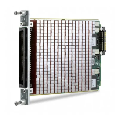

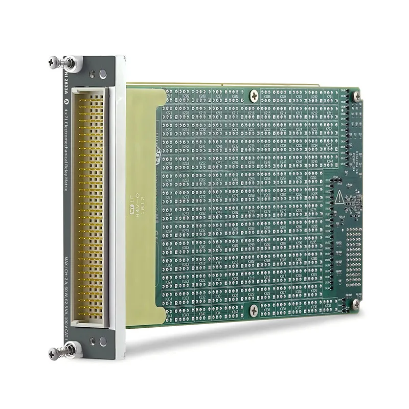
SWB-2833 4 × 71 2 A 2-Wire Matrix for NI SwitchBlock
The NI SWB-2833 is a 2-wire, 4 × 71 electromechanical relay matrix card for NI SwitchBlock systems. It provides 272 two-wire crosspoints for applications that must route paired conductors, such as a source and return path, under software control. The module is designed for higher-power routing than the 281x reed relay matrix family.
The SWB-2833 supports 2 A maximum switching and carry current per channel, 100 V CAT I operation, and 60 W switching power per channel and crosspoint. It requires an NI PXI-2800 SwitchBlock carrier and cannot operate as a standalone PXI module.
Key Features of the SWB-2833
- 2-wire 4 × 71 electromechanical relay matrix
- 272 two-wire crosspoints
- 2.0 A maximum switching and carry current per channel
- 100 V CAT I maximum switching voltage
- 60 W / 62.5 VA maximum switching power per channel
- Four channels can operate simultaneously at maximum current
- Typical bandwidth of at least 10 MHz at -3 dB with 50 Ω termination
- Typical thermal EMF below 10 μV
- Latching electromechanical relays with field-replaceable relay support
- 160-position DIN I/O connector
SWB-2833 Technical Specifications
| Parameter | Specification |
|---|---|
| Topology | 2-wire 4 × 71 matrix |
| Crosspoints | 272 two-wire crosspoints |
| Relay Type | Latching electromechanical relay |
| Relay Contact Material | Palladium-ruthenium, gold covered |
| Maximum Switching Voltage | 100 V row-to-column; 100 V CAT I row/column-to-ground |
| Maximum Switching / Carry Current | 2.0 A per channel |
| Maximum Switching Power | 60 W / 62.5 VA per channel; 60 W per crosspoint |
| Channels at Maximum Current | 4 simultaneous channels |
| DC Path Resistance | Initial 1 Ω; end-of-life ≥2 Ω |
| Open-Channel Resistance | >10 GΩ |
| Thermal EMF, Typical | <10 μV |
| Bandwidth, Typical | ≥10 MHz at -3 dB, 50 Ω termination |
| Minimum Switching Load | 20 mV / 10 mA |
| Analog Bus | Eight lines: AB<0..7> |
| Relay Operation / Release Time, Typical | <5 ms |
| Mechanical Relay Life | 1 × 10⁸ operations, no load |
| I/O Connector | 160-position DIN |
| Operating Temperature | 0 °C to 55 °C |
| Dimensions | 11.2 cm × 1.2 cm × 17.1 cm |
| Weight | 373 g |
The 60 W rating applies per channel and per crosspoint, but the module is limited to four simultaneous channels at maximum current. A system-level power and thermal review is required whenever several high-current paths are active at the same time.
SWB-2833 Part Number and Accessories
| Item | Part Number | Selection Note |
|---|---|---|
| NI 2833A / SWB-2833 Type A | 781420-33 | Provides row and column access; one Type A card is used per SwitchBlock system. |
| NI 2833B / SWB-2833 Type B | 781421-33 | Expansion card for larger SwitchBlock matrix configurations. |
| NI PXI-2800 | Configuration dependent | Required SwitchBlock carrier for operation in a PXI chassis. |
| SH160F-160M-NI SwitchBlock Cable | 153028-01 | Compatible 160-position cable for external matrix wiring. |
| NI TBX-2808 | 781420-08 | Compatible unshielded screw-terminal accessory. |
SWB-2833 Matrix Architecture and Integration
2-Wire High-Power Routing
The SWB-2833 switches two conductors together for each routed path. This is useful when an application requires both the source and return path to be switched through the matrix, rather than routing only one signal conductor. The 4 × 71 topology is appropriate for systems requiring four shared high-power paths across many DUT connections.
Before selecting the module, confirm whether the application requires 2-wire routing, the required current per path, total simultaneously active current, switching power, and the number of required rows and columns.
Type A and Type B Card Selection
The NI 2833A and NI 2833B share the same 2-wire, 4 × 71 electrical topology. The Type A card provides row and column access to the SwitchBlock analog bus; the Type B card is used for expansion. A complete SwitchBlock system can contain only one Type A card.
Load, Timing, and Relay Life
The SWB-2833 uses latching electromechanical relays and has a typical operate/release time below 5 ms. Additional settling time may be required by the connected source, DUT, cable assembly, or measurement instrument.
NI specifies electrical relay life under resistive loads below 10 pF of up to 2.5 × 10⁶ operations at 10 V and 100 mA, 1 × 10⁶ operations at 10 V and 1 A, 5 × 10⁵ operations at 30 V and 1 A, and 1 × 10⁵ operations at 30 V and 2 A. Actual lifetime depends on voltage, current, switching frequency, cable capacitance, and load type.
The module supports field replacement of failed relays. This can be valuable in long-life fixtures or systems with repetitive high-cycle routing, but the load profile should still be controlled to preserve relay life.
Safety and Measurement Considerations
The SWB-2833 is rated for Measurement Category I only and must not be connected to mains circuits or Category II, III, or IV measurements. In a mixed-card or bridged SwitchBlock system, the lowest applicable safety voltage rating governs the connected system.
NI specifies a 20 mV / 10 mA minimum switching load and does not recommend this minimum load for 2-wire resistance measurements. Use a dedicated DMM or switching topology suitable for the required resistance-measurement accuracy when low-level resistance is the primary application.
SWB-2833 Applications
Higher-Power Functional Test
The SWB-2833 is suitable for automated test systems that must route power, load, or stimulus paths with current requirements above the capability of low-current reed matrices. Its 2 A switching capacity is useful for controlled functional test and production fixtures within the 100 V CAT I and 60 W limits.
Two-Wire DUT Connection Routing
The 2-wire topology supports routing paired conductors between shared instruments and multiple DUT points. Typical applications include switching power supply outputs, source-and-return connections, and other test paths where both conductors must be controlled together.
Scalable SwitchBlock Configurations
Multiple SWB-2833 cards can be used in a PXI-2800 carrier or expanded between carriers when the required routing system exceeds one matrix card. The final configuration should be planned around total high-current paths, simultaneous load demand, cable selection, and terminal wiring.
SWB-2833 Comparison
SWB-2833 vs SWB-2834
The NI SWB-2834 provides an 8 × 34, 2-wire electromechanical matrix. Choose SWB-2833 for four rows and higher column density; choose SWB-2834 when the application needs more shared two-wire paths and fewer DUT nodes per row.
SWB-2833 vs SWB-2810
The NI SWB-2810 is a 1-wire, 4 × 43 reed matrix rated at 1 A, 150 V, and 20 W. Choose SWB-2833 when the application requires 2-wire routing and up to 2 A switching. Choose SWB-2810 when one-wire routing and lower switching current are sufficient.
Recommended Related Products
- NI PXI-2800 — required SwitchBlock carrier.
- SH160F-160M-NI SwitchBlock Cable, 153028-01 — compatible cable for SWB-2833 external wiring.
- NI TBX-2808, 781420-08 — compatible screw-terminal accessory.
- NI 2806 Expansion Bridge — optional accessory for expanding compatible SwitchBlock carriers.
Request a Quote
Contact PXISOURCE at sales@pxisource.com or WhatsApp for the NI SWB-2833. Please provide the required Type A or Type B version, quantity, carrier requirement, cable and terminal accessory, switching voltage, current, load type, and number of simultaneous high-current paths.
FAQ
Can the SWB-2833 operate directly in a PXI chassis?
No. The SWB-2833 is a SwitchBlock matrix card and requires an NI PXI-2800 carrier for operation in a PXI chassis.
What does the 2-wire topology mean?
The SWB-2833 routes two conductors together for each connection. It is appropriate when both a source path and its return path must be switched through the matrix.
Can all channels carry 2 A simultaneously?
No. NI specifies that four channels can operate simultaneously at maximum current. Review the complete carrier configuration and load sequence before operating multiple high-current paths.
Can SWB-2833 be used for low-level 2-wire resistance measurements?
NI does not recommend the minimum 20 mV / 10 mA switching load for 2-wire resistance measurements. Use a measurement architecture appropriate for the required resistance accuracy and test current.
Can the SWB-2833 switch mains voltage?
No. The SWB-2833 is rated for Measurement Category I only and must not be connected to mains circuits or Category II, III, or IV signals.















