




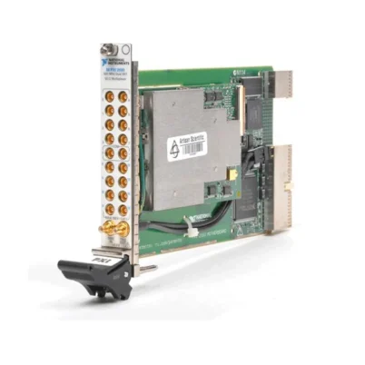
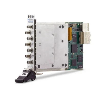
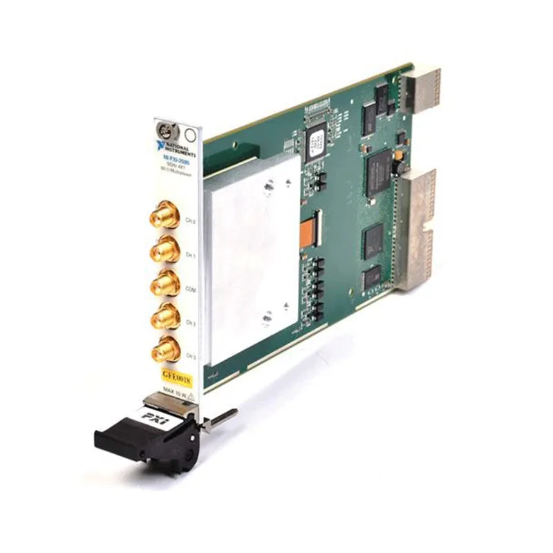
PXI-2595 5 GHz 4×1 50 Ω PXI RF Multiplexer
The PXI-2595 is a high-frequency PXI RF multiplexer switch module designed for automated test equipment, RF signal routing and communications-device validation. It provides a single unterminated 4×1 multiplexer capable of connecting one of four RF input channels to a common measurement or stimulus connection.
With a DC to 5 GHz operating range, 50 Ω characteristic impedance and direct SMA connectivity, the PXI-2595 can route RF, microwave, communications and broadband test signals. Its electromechanical latching relays provide low insertion loss, strong channel isolation and broadband operation extending to DC.
Key Features of the PXI-2595
- Single 4×1 RF multiplexer topology
- Four input channels and one common connection
- DC to 5 GHz operating frequency range
- 50 Ω nominal characteristic impedance
- Five SMA front-panel connectors
- Electromechanical latching relays
- Less than 0.7 dB insertion loss through 1 GHz
- Less than 1.7 dB insertion loss through 3 GHz
- Less than 2.8 dB insertion loss through 5 GHz
- Greater than 70 dB isolation through 1 GHz
- Greater than 55 dB isolation through 3 GHz
- Greater than 30 dB isolation through 5 GHz
- 10 W maximum RF switching power
- 30 V maximum switching voltage
- 0.5 A maximum switching and carry current
- Less than 1 ps typical channel-to-channel skew
- Less than 700 ps typical propagation delay
- 45 channels/s maximum scan rate
- Onboard relay-count tracking
- PXI hardware trigger support
- NI-SWITCH and NI Switch Executive compatibility
PXI-2595 Technical Specifications
| Product Model | PXI-2595 |
|---|---|
| Part Number | 778572-95 |
| Product Type | PXI RF multiplexer switch module |
| Topology | Single 4×1 multiplexer |
| Termination | Unterminated |
| Number of Input Channels | 4 |
| Number of Common Connections | 1 |
| Frequency Range | DC to 5 GHz |
| Characteristic Impedance | 50 Ω nominal |
| Maximum Insertion Loss through 1 GHz | Less than 0.7 dB; less than 0.4 dB typical |
| Maximum Insertion Loss through 3 GHz | Less than 1.7 dB; less than 1.0 dB typical |
| Maximum Insertion Loss through 5 GHz | Less than 2.8 dB; less than 2.0 dB typical |
| Maximum VSWR through 1 GHz | Less than 1.25; less than 1.1 typical |
| Maximum VSWR through 3 GHz | Less than 1.40; less than 1.3 typical |
| Maximum VSWR through 5 GHz | Less than 1.85; less than 1.5 typical |
| Isolation through 1 GHz | Greater than 70 dB; greater than 78 dB typical |
| Isolation through 3 GHz | Greater than 55 dB; greater than 69 dB typical |
| Isolation through 5 GHz | Greater than 30 dB; 38 dB typical |
| Maximum Switching Voltage | 30 V |
| Maximum Switching Current | 0.5 A |
| Maximum Carry Current | 0.5 A |
| Maximum RF Switching Power | 10 W from channel to common |
| Initial DC Path Resistance | Less than 0.25 Ω |
| End-of-Life DC Path Resistance | 1.0 Ω or greater |
| Typical Channel-to-Channel Skew | Less than 1 ps |
| Typical Propagation Delay | Less than 700 ps |
| Typical Rise Time | Less than 65 ps |
| Maximum Scan Rate | 45 channels/s |
| Maximum Relay Operate Time | 10.4 ms |
| Relay Type | Electromechanical latching |
| Expected Mechanical Relay Life | 1,000,000 cycles |
| Expected Electrical Relay Life | 300,000 cycles at 30 V, 10 mA DC resistive |
| Front-Panel Connectors | 5 SMA jacks |
| Operating Temperature | 0°C to 55°C |
| Storage Temperature | -20°C to 70°C |
| Relative Humidity | 5% to 85%, noncondensing |
| Dimensions | 21.6 × 2.0 × 13.0 cm |
| Module Format | 3U, single-slot PXI/cPCI module |
| Software Support | NI-SWITCH and NI Switch Executive |
PXI-2595 Part Number and Accessories
| Item | Part Number | Description |
|---|---|---|
| PXI-2595 | 778572-95 | 5 GHz, 50 Ω, unterminated 4×1 PXI RF multiplexer |
| SMA-100 Cable | 763443-01 | 12.7 cm SMA male-to-male flexible RF cable |
| SMA-100 Cable | 763444-01 | 38.1 cm SMA male-to-male flexible RF cable |
| SMA Plug to SMB Jack Adapter | 779674-01 | SMA male to SMB male adapter for compatible RF connections |
| 50 Ω SMA Termination Plug | 778353-01 | 50 Ω termination for unused RF connections |
| RF Torque Screwdriver and SMA Driver Bit | 780895-01 | Tool kit for applying controlled torque to SMA connectors |
The PXI-2595 uses five SMA jacks: four input channels and one common connection. Use properly rated 50 Ω RF cables and follow the recommended SMA connector torque to preserve repeatable high-frequency performance.
4×1 RF Multiplexer Architecture
The PXI-2595 contains a single 4×1 multiplexer. Software can connect any one of four RF channels to the common port, allowing several signal sources or devices under test to share one RF instrument.
A typical configuration connects the common port to a spectrum analyzer, RF digitizer, signal generator, receiver or other 50 Ω instrument. The four selectable channels can connect to separate devices, antennas, test points or fixture paths.
The multiplexer is normally configured with only one active channel connected to the common port. Engineers should prevent conflicting sources from being connected together and verify that all signals remain within the voltage, current and RF power ratings.
DC to 5 GHz RF Signal Routing
The PXI-2595 can route signals from DC through 5 GHz. This broad operating range supports baseband, intermediate-frequency and RF signals within a single programmable switching module.
Typical applications include communications-device testing, RF component characterization, receiver and transmitter validation, automated production testing and general-purpose laboratory signal routing.
The bandwidth of the complete test system also depends on the cables, connectors, adapters, fixtures and connected instruments. Every component should be selected for the required frequency range and 50 Ω impedance.
50 Ω Characteristic Impedance
The PXI-2595 is designed for 50 Ω RF test systems. This impedance is widely used by signal generators, spectrum analyzers, network analyzers, digitizers and wireless communications equipment.
Maintaining consistent 50 Ω impedance helps reduce reflections, mismatch loss and standing waves. Avoid mixing 50 Ω and 75 Ω cables or terminations unless the system includes a suitable impedance-matching network.
Insertion Loss Performance
The PXI-2595 specifies insertion loss below 0.7 dB through 1 GHz, below 1.7 dB through 3 GHz and below 2.8 dB through 5 GHz. Its typical insertion loss is lower under representative operating conditions.
Insertion loss increases with frequency and is also affected by external cables and adapters. For accurate amplitude measurements, characterize the complete path and apply path-loss compensation in the measurement software when necessary.
RF Isolation Performance
Channel isolation is greater than 70 dB through 1 GHz, greater than 55 dB through 3 GHz and greater than 30 dB through 5 GHz. High isolation helps prevent energy on unselected channels from reaching the active measurement path.
System isolation can be reduced by poorly shielded cables, external fixture coupling, damaged connectors and improper grounding. Keep high-power sources physically separated from sensitive receiver paths.
VSWR and Signal Integrity
The PXI-2595 provides controlled VSWR performance across its frequency range. Maximum VSWR is below 1.25 through 1 GHz, below 1.40 through 3 GHz and below 1.85 through 5 GHz.
Good VSWR helps reduce signal reflections when the switch is used with matched 50 Ω equipment. Actual system performance should be evaluated with the final cables, adapters, fixtures and instruments installed.
Unterminated RF Architecture
The PXI-2595 is an unterminated multiplexer. When a channel is not selected, it is not automatically connected to an internal 50 Ω termination.
If an RF source requires a defined load while disconnected, install an appropriate external termination or select a switch architecture with internal termination. This is especially important when open-channel reflections could affect the source or test result.
10 W RF Switching Capability
The maximum channel-to-common RF switching power is 10 W. The signal must also remain within the 30 V maximum switching voltage and 0.5 A maximum switching-current ratings.
The usable RF power can depend on frequency, impedance match and switching conditions. Confirm all simultaneous electrical limits instead of evaluating only the 10 W rating.
Cold Switching and Relay Protection
For maximum relay life and repeatable RF performance, remove or reduce RF power before changing routes whenever the test sequence permits. This practice is commonly referred to as cold switching.
Switching active RF signals can stress relay contacts, degrade signal integrity and shorten electrical life. The module should not be treated as protection against excessive source power or unexpected RF transients.
Electromechanical Latching Relays
The PXI-2595 uses electromechanical latching relays. These relays provide broadband signal routing that extends to DC and maintain their selected state without continuously energizing the relay coil.
Relay contacts have a finite operating life. The expected mechanical life is one million cycles, while electrical life depends on the switched voltage, current, power, load type and switching conditions.
Relay-Count Tracking
Onboard relay-count tracking records switching activity for the module’s relays. Maintenance teams can use this information to identify heavily used channels and estimate when preventive service may be required.
Where the fixture architecture permits, engineers can distribute frequently used routes across different channels to balance relay usage and reduce unexpected test-system downtime.
Low Timing Skew and Propagation Delay
The PXI-2595 provides less than 1 ps typical channel-to-channel skew and less than 700 ps typical propagation delay. Typical signal rise time is less than 65 ps.
These characteristics support high-frequency signal routing where consistent electrical path length is important. External cable length and fixture geometry can introduce substantially more skew than the switch itself, so matched cables may be required.
Hardware Triggering and Scanning
The module supports PXI hardware triggering for coordinated route changes in automated test systems. Hardware triggers can synchronize the switch with RF sources, digitizers and other PXI instruments.
The PXI-2595 provides a maximum scan rate of 45 channels per second and a maximum relay operating time of 10.4 ms. Test software should also include any settling time required by the signal source, DUT and measurement instrument.
Typical PXI-2595 Applications
- Automated RF test equipment
- Wireless communications testing
- RF source selection
- Spectrum analyzer input selection
- RF digitizer signal routing
- Receiver and transmitter validation
- RF component characterization
- Antenna-path selection
- Production functional testing
- Research and laboratory automation
- Broadband signal routing
- Multipoint RF measurements
Automated RF Test Systems
In an automated test system, the PXI-2595 can connect several RF paths to one expensive measurement instrument. Software selects the required device or test point before triggering the measurement.
This architecture reduces manual cable changes and improves instrument utilization. Multiple switch modules can be installed when the system requires additional channels or separate switching banks.
Wireless Device Validation
The module can route RF signals during the validation of radios, receivers, transmitters and wireless components operating below 5 GHz. Test software can select different device outputs, stimulus paths or antenna connections.
For transmitter testing, confirm that the maximum output power and transient behavior remain within the PXI-2595 ratings. External attenuators, directional couplers or protection components may be required for higher-power transmitters.
RF Instrument Sharing
The 4×1 configuration allows four DUT connections to share one spectrum analyzer, digitizer or receiver. Alternatively, four RF sources can be selected sequentially and routed to one device under test.
Before switching between sources, configure inactive sources appropriately and prevent them from driving unterminated channels when that condition could cause instability or excessive reflection.
SMA Connector Integration
The five front-panel SMA connectors provide direct compatibility with common 50 Ω RF cables and instruments. Use quality cables with the required bandwidth and avoid unnecessary adapters.
Inspect connectors before installation and keep them free of contamination. Excessive or insufficient connector torque can damage the interface or produce inconsistent RF measurements.
NI-SWITCH Software Support
The PXI-2595 is controlled through the NI-SWITCH instrument driver. NI-SWITCH provides functions for initializing the module, connecting and disconnecting channels, creating scan lists, configuring triggers and reading relay-count information.
The driver supports integration with LabVIEW, LabWindows/CVI and compatible text-based programming environments. Route control can be included directly within an automated RF measurement sequence.
NI Switch Executive Integration
NI Switch Executive allows users to define signal paths with descriptive route names instead of controlling physical relays directly. This can make applications easier to develop and maintain.
Named routes are especially useful in systems containing multiple switch modules and complex test fixtures. Hardware changes can often be managed within route configuration without rewriting the complete test application.
PXI Chassis Integration
The PXI-2595 occupies one slot in a compatible 3U PXI chassis. It can be installed alongside RF signal generators, digitizers, controllers and other PXI measurement modules.
Before installation, verify chassis compatibility, slot availability, controller communication and NI-SWITCH software support. Provide adequate clearance for the five SMA cables and avoid excessive mechanical stress on the front-panel connectors.
PXI-2595 Troubleshooting
The PXI-2595 Is Not Detected in NI MAX
Confirm that the module is fully installed in a compatible PXI slot. Check chassis power, controller communication and the NI-SWITCH driver installation, then restart NI Measurement & Automation Explorer.
No Signal Appears at the Common Port
Verify that the correct channel-to-common route is closed. Check the RF source, cable continuity, SMA connector engagement and receiving-instrument configuration.
Insertion Loss Is Higher Than Expected
Inspect the cables, connectors and adapters for damage or contamination. Confirm that every component supports 50 Ω operation and the required frequency. Measure and compensate for the complete path loss when necessary.
VSWR Is Excessive
Verify that the source, load, cables and termination components all use 50 Ω impedance. Remove unnecessary adapters and check SMA connector torque. Add an external termination if an unused source requires a defined load.
Signals Leak Between Channels
Check fixture shielding, cable routing and grounding. Separate strong RF sources from sensitive receiver paths and inspect the external wiring for unintended coupling between channels.
A Relay Does Not Change State
Verify the commanded route and review the relay-count information. Disconnect external signals and test the channel with a known low-level source. A heavily used or overstressed relay may require service.
Relay Life Is Shorter Than Expected
Check whether routes are being changed while RF power is present. Verify the source voltage, current and power, and use cold switching whenever possible. Also check for capacitive discharge and transient energy.
High-Frequency Measurements Are Not Repeatable
Use phase-stable RF cables, avoid moving cables during measurements and allow sufficient settling time after switching. Calibrate the system with the switch and external signal path in their final configuration.
PXI-2595 Comparison with Similar RF Switch Modules
| Model | Primary Configuration | Best Suited For |
|---|---|---|
| PXI-2594 | 2.5 GHz, 50 Ω, 4×1 multiplexer | Lower-frequency 4×1 RF routing |
| PXI-2595 | 5 GHz, 50 Ω, unterminated 4×1 multiplexer | General-purpose RF routing through 5 GHz |
| PXI-2596 | 26.5 GHz, dual 6×1 multiplexer | High-frequency and microwave routing with greater density |
| PXI-2597 | 26.5 GHz, 50 Ω, terminated 6×1 multiplexer | Microwave routing requiring internal termination |
| PXI-2598 | 26.5 GHz transfer-switch architecture | High-frequency transfer and insert-bypass routing |
PXI-2595 vs PXI-2594
The PXI-2594 and PXI-2595 both provide a 50 Ω, 4×1 RF multiplexer topology. The PXI-2594 supports signals through 2.5 GHz, while the PXI-2595 extends the operating range to 5 GHz.
Choose the PXI-2595 when the application requires frequency coverage above 2.5 GHz. Choose the PXI-2594 when the lower bandwidth meets the test requirement.
PXI-2595 vs PXI-2596
The PXI-2595 provides one 4×1 multiplexer through 5 GHz. The PXI-2596 provides two 6×1 multiplexers with frequency coverage extending to 26.5 GHz.
Select the PXI-2595 for general-purpose RF switching below 5 GHz. Select the PXI-2596 when the system requires microwave-frequency coverage, more channels, lower insertion loss or substantially higher RF carry power.
PXI-2595 vs PXI-2597
The PXI-2595 is an unterminated 4×1 multiplexer with a 5 GHz bandwidth. The PXI-2597 is a terminated 6×1 multiplexer supporting frequencies through 26.5 GHz.
The PXI-2595 is appropriate for lower-frequency applications that do not require internal termination. The PXI-2597 is better suited to microwave systems where terminated unselected channels help control reflections.
Recommended Related Products
- PXI-2594 2.5 GHz 4×1 RF Multiplexer
- PXI-2596 26.5 GHz Dual 6×1 RF Multiplexer
- PXI-2597 26.5 GHz Terminated 6×1 RF Multiplexer
- PXI-2598 26.5 GHz RF Transfer Switch
- PXI-2599 26.5 GHz RF Switch Module
- View More NI PXI and PXI Express Modules
Selecting the Right RF Multiplexer
Choose the PXI-2595 when the application requires a single 4×1 multiplexer, 50 Ω impedance, SMA connectivity and operation through 5 GHz. It provides a practical balance of RF performance, compact size and software-controlled routing.
Choose the PXI-2594 when 2.5 GHz bandwidth is sufficient. Consider the PXI-2596 or PXI-2597 when the test system requires additional channels, internal termination or frequency coverage extending to 26.5 GHz.
Why Choose the PXI-2595?
- Routes four RF paths to one common connection
- Supports signals from DC through 5 GHz
- Maintains 50 Ω RF system impedance
- Provides direct SMA connectivity
- Offers low insertion loss and strong isolation
- Supports up to 10 W RF switching power
- Includes onboard relay-count tracking
- Supports automated scanning and PXI triggering
- Integrates with NI-SWITCH and NI Switch Executive
- Occupies only one PXI chassis slot
Frequently Asked Questions
What Is the PXI-2595?
The PXI-2595 is a 50 Ω, 4×1 PXI RF multiplexer that routes one of four input channels to a common connection over a DC to 5 GHz frequency range.
What Is the PXI-2595 Part Number?
The standard NI part number for the PXI-2595 is 778572-95.
What Is the Maximum Frequency?
The PXI-2595 supports RF signals from DC through 5 GHz.
How Many Channels Does the PXI-2595 Have?
The module provides four selectable RF input channels and one common connection in a single 4×1 multiplexer.
Does the PXI-2595 Use 50 Ω or 75 Ω Impedance?
The PXI-2595 uses 50 Ω nominal characteristic impedance.
What Is the Maximum RF Power?
The maximum channel-to-common RF switching power is 10 W, subject to the applicable voltage, current, frequency and load limitations.
Are the Unselected Channels Terminated?
No. The PXI-2595 is an unterminated multiplexer. External 50 Ω terminations should be used when required by the source or test configuration.
What Connectors Does the PXI-2595 Use?
The front panel provides five SMA jacks: four channel connectors and one common connector.
What Type of Relays Does It Use?
The module uses electromechanical latching relays.
Does the PXI-2595 Track Relay Usage?
Yes. Onboard relay-count tracking records relay operations and supports preventive maintenance planning.
Which Software Controls the PXI-2595?
The PXI-2595 is controlled with NI-SWITCH and can be integrated into named-route applications using NI Switch Executive.
Can the PXI-2595 Switch Active RF Signals?
Active RF switching should be minimized. Removing or reducing RF power before changing routes helps preserve signal integrity and extend relay life.
Request a Quote for the PXI-2595
Contact us for current availability, condition, lead time and project pricing for the PXI-2595 5 GHz 4×1 50 Ω PXI RF Multiplexer. We can also help identify compatible SMA cables, termination plugs, PXI chassis and alternative NI RF switch modules for your automated test system.















