






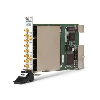
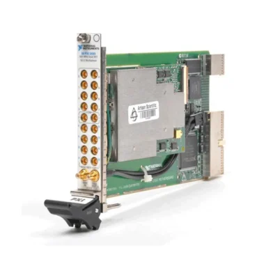
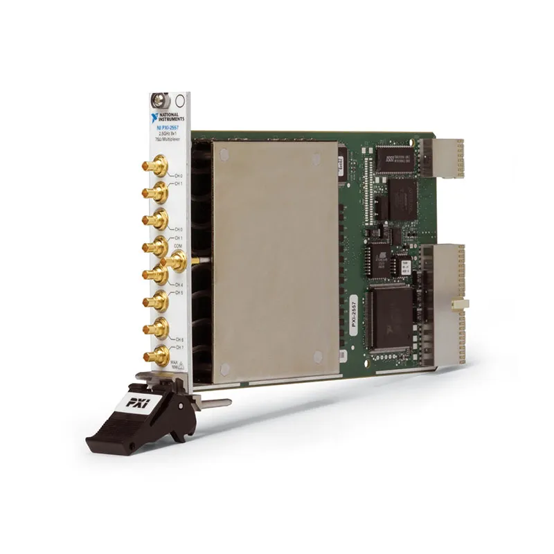
PXI-2557 8×1 2.5 GHz 75 Ω PXI RF Multiplexer
The PXI-2557 is a high-density PXI RF multiplexer designed to route one of eight 75 Ω RF or video signals to a single common connection. Its 8×1 topology, DC to 2.5 GHz operating range and electromechanical relay architecture make it suitable for cable television, video, tuner, communications and automated RF test systems.
The module combines eight input channels and one common connection in a single-slot PXI instrument. It provides low insertion loss, good isolation and controlled 75 Ω impedance for test systems that need to connect several devices or signal sources to one RF analyzer, digitizer or other measurement instrument.
Key Features of the PXI-2557
- Single 8×1 RF multiplexer topology
- Eight input channels and one common connection
- DC to 2.5 GHz operating frequency range
- 75 Ω characteristic impedance
- Electromechanical latching relays
- Less than 1.1 dB insertion loss through 1 GHz
- Less than 2.0 dB insertion loss through 2.5 GHz
- Greater than 41 dB typical isolation through 2.5 GHz
- 10 W maximum RF switching power
- 30 V maximum switching voltage
- 0.5 A maximum switching and carry current
- Less than 25 ps typical channel-to-channel skew
- 1.2 ns typical propagation delay
- 10.4 ms maximum relay operating time
- Onboard relay-count tracking
- PXI hardware trigger support
- NI-SWITCH software compatibility
- Single-slot 3U PXI module
PXI-2557 Technical Specifications
| Product Model | PXI-2557 |
|---|---|
| Part Number | 778572-57 |
| Product Type | PXI RF multiplexer switch module |
| Topology | Single 8×1 multiplexer |
| Termination | Unterminated |
| Number of Input Channels | 8 |
| Number of Common Connections | 1 |
| Frequency Range | DC to 2.5 GHz |
| Characteristic Impedance | 75 Ω |
| Maximum Insertion Loss through 1 GHz | Less than 1.1 dB |
| Maximum Insertion Loss through 2.5 GHz | Less than 2.0 dB |
| Typical Isolation through 1 GHz | Greater than 48 dB |
| Typical Isolation through 2.5 GHz | Greater than 41 dB |
| Maximum VSWR through 1 GHz | Less than 1.25 |
| Maximum VSWR through 2.5 GHz | Less than 1.6 |
| Maximum Switching Voltage | 30 V |
| Maximum Switching Current | 0.5 A per channel |
| Maximum Carry Current | 0.5 A per channel |
| Maximum RF Switching Power | 10 W from channel to common |
| Typical Initial DC Path Resistance | Less than 0.35 Ω |
| Typical Channel-to-Channel Skew | Less than 25 ps |
| Typical Propagation Delay | 1.2 ns |
| Typical Rise Time | 91 ps |
| Maximum Relay Operate Time | 10.4 ms |
| Relay Type | Electromechanical latching |
| Mechanical Relay Life | 1,000,000 cycles |
| Input Trigger Sources | PXI trigger lines 0 through 7 |
| Minimum Trigger Pulse Width | 150 ns |
| Front-Panel Connections | 9 mini-75 Ω SMB jacks |
| Operating Temperature | 0°C to 55°C |
| Module Format | 3U, single-slot PXI module |
| Software Support | NI-SWITCH and NI Switch Executive |
PXI-2557 Part Number and Accessories
| Item | Part Number | Description |
|---|---|---|
| PXI-2557 | 778572-57 | 2.5 GHz, 75 Ω, 8×1 PXI RF multiplexer module |
| Mini-75 Ω SMB Plug-to-Plug Cable | 197211-0R3 | 0.3 m cable for short 75 Ω RF connections |
| Mini-75 Ω SMB Plug-to-Plug Cable | 197211-01 | 1 m cable for 75 Ω RF system integration |
| Type-F Female to Mini-75 Ω SMB Plug Cable | 197210-0R3 | 0.3 m adapter cable for Type-F RF equipment |
The PXI-2557 uses miniature 75 Ω SMB front-panel connections. Confirm the connector type, cable length, impedance and frequency rating before selecting cables or designing a test fixture.
8×1 RF Multiplexer Architecture
The PXI-2557 contains one common connection and eight independently selectable input channels. Software can connect any one of the eight channels to the common port, allowing several RF sources or devices under test to share a single instrument.
A typical system connects the common port to an RF analyzer, digitizer or measurement receiver. Each channel can then be connected to a separate tuner, video source, cable assembly or device under test. Test software selects the required channel without manual cable changes.
The multiplexer is normally operated with one channel connected to the common at a time. Applications should avoid creating unintended signal conflicts between multiple sources and should remain within the module’s RF power, voltage and current ratings.
75 Ω RF and Video Signal Routing
The PXI-2557 is designed for 75 Ω environments commonly used in cable television, video distribution and broadcast test systems. Maintaining the correct impedance helps reduce reflections and measurement errors throughout the RF signal path.
All external components should also maintain 75 Ω impedance, including cables, adapters, connectors, fixtures and instrument inputs. Mixing 50 Ω and 75 Ω components can increase mismatch loss and degrade VSWR performance.
DC to 2.5 GHz Frequency Range
The module supports signals from DC through 2.5 GHz. This frequency range accommodates baseband video, intermediate-frequency signals, television and cable bands, tuner test signals and other broadband 75 Ω applications.
Overall system bandwidth depends on more than the switch module. Cable length, connector quality, adapters, fixture layout, source impedance and load impedance can all affect high-frequency performance.
Insertion Loss Performance
The PXI-2557 specifies less than 1.1 dB insertion loss through 1 GHz and less than 2.0 dB through 2.5 GHz. Low insertion loss helps preserve signal amplitude between the selected input and common connection.
For accurate RF measurements, characterize the complete signal path and compensate for cable and switch losses where necessary. Calibration should be performed using the same cables, adapters and routing configuration employed during testing.
RF Isolation
Typical channel isolation is greater than 48 dB through 1 GHz and greater than 41 dB through 2.5 GHz. Isolation reduces leakage from unselected channels into the active measurement path.
System-level isolation can be affected by external cables, connector spacing, fixture shielding and grounding. Keep sensitive signal paths separated from high-power RF sources and use properly shielded 75 Ω cabling.
VSWR and Impedance Matching
The PXI-2557 provides a maximum VSWR below 1.25 through 1 GHz and below 1.6 through 2.5 GHz. These ratings help limit reflections when the module is connected to properly matched 75 Ω equipment.
Unused channels in the unterminated multiplexer are not internally connected to matched loads. If the test architecture requires defined termination on unselected inputs, provide suitable external 75 Ω terminations or consider a terminated RF switch configuration.
10 W RF Power Capability
The maximum RF switching power from a channel to the common connection is 10 W. The applied signal must also remain within the module’s 30 V maximum switching voltage and 0.5 A maximum current ratings.
RF power limits can vary with frequency, load mismatch and switching conditions. Avoid operating the relays while high-power RF energy is present whenever possible because cold switching generally reduces contact stress and extends relay life.
Electromechanical Latching Relays
The PXI-2557 uses electromechanical latching relays. Latching operation allows a relay to maintain its selected state without continuous coil power, helping reduce internal heat generation.
Electromechanical relays provide a broadband signal path extending to DC, but relay contacts have a finite service life. Switching high-power, capacitive or active signals can shorten electrical life compared with low-level cold-switching operation.
Relay-Count Tracking
Onboard relay-count tracking records the number of operations performed by each relay. This information helps users monitor channel utilization and plan preventive maintenance in production and laboratory test systems.
Frequently used routes can be identified before relay wear affects test reliability. Where the fixture design permits, switching activity can be distributed across channels to balance relay usage.
Hardware Triggering and Automated Scanning
The PXI-2557 can accept hardware triggers from PXI trigger lines 0 through 7. Hardware triggering allows route changes to be coordinated with digitizers, RF instruments and other modules in an automated PXI test system.
Trigger-controlled scanning can provide more repeatable timing than software commands alone. The complete sequence should allow sufficient time for relay operation, signal settling and instrument acquisition.
Typical PXI-2557 Applications
- Cable television tuner testing
- Broadcast video test systems
- 75 Ω RF signal routing
- Automated tuner validation
- Set-top box production testing
- Video distribution equipment testing
- RF analyzer input selection
- Broadband signal-source selection
- Cable and connector testing
- Communications equipment validation
- Laboratory RF automation
- Production functional testing
Multiple-Tuner Test Systems
The 8×1 topology is well suited for test systems that connect several video or cable tuners to one RF analyzer. Software can select each device sequentially, perform the required measurements and record the results without moving cables.
This configuration helps improve equipment utilization because one measurement instrument can serve as many as eight test paths. Additional PXI-2557 modules can be installed when a system requires more than eight inputs.
RF Analyzer and Digitizer Integration
The common connection can be routed to a 75 Ω RF analyzer, digitizer, receiver or other measurement instrument. Each channel can connect to a separate source, output or test fixture path.
When the receiving instrument uses a 50 Ω input, an appropriate impedance-matching device may be required. A simple connector adapter changes the physical interface but does not convert the electrical impedance.
NI-SWITCH Software Support
The PXI-2557 is controlled through the NI-SWITCH instrument driver. NI-SWITCH provides functions for initializing the module, connecting and disconnecting routes, creating scan lists, configuring triggers and retrieving relay-count information.
The driver can be used with LabVIEW, LabWindows/CVI and supported text-based programming environments. Test applications can select RF paths programmatically as part of automated measurement sequences.
NI Switch Executive Integration
NI Switch Executive allows developers to assign meaningful names to channels and routes. Instead of managing physical relay names directly, application software can connect routes representing devices, instruments or fixture locations.
Named routes are particularly useful in systems containing several RF switch modules. They make test sequences easier to understand and help separate application logic from physical wiring details.
PXI Chassis Integration
The PXI-2557 is a single-slot 3U PXI module. It can be installed with RF analyzers, digitizers, signal generators, digital instruments and other PXI modules to create a compact automated test system.
Before installation, verify chassis compatibility, slot availability, controller support and the required NI-SWITCH driver version. Allow sufficient front-panel clearance for all nine RF connectors and avoid excessive bending force on miniature SMB cables.
PXI-2557 Troubleshooting
The PXI-2557 Is Not Detected in NI MAX
Confirm that the module is fully seated in a compatible PXI slot. Check chassis power, controller communication and NI-SWITCH installation, then restart NI Measurement & Automation Explorer and rescan the system.
No Signal Appears at the Common Port
Verify that the correct channel-to-common route is closed. Check cable continuity, connector seating, source output and analyzer configuration. Confirm that the channel names in the software correspond to the physical front-panel connections.
Insertion Loss Is Higher Than Expected
Inspect every cable, adapter and connector in the signal path. Confirm that all components have 75 Ω impedance and adequate bandwidth. Damaged connectors, long cables and 50 Ω components can increase measured loss.
Signal Reflections or Poor VSWR Occur
Confirm that the source, load, cables and terminations are all designed for 75 Ω operation. Remove unnecessary adapters and keep cables as short as practical. Add external 75 Ω terminations where required by the test configuration.
Signals Leak Between Channels
Check external fixture shielding, cable routing and grounding. Separate high-level RF sources from sensitive measurement paths and verify that unselected sources are not coupling through external wiring.
A Relay Does Not Change State
Check the route command, relay status and relay-count data. Disconnect the external circuit and test the channel with a known signal path. If the fault remains, the relay may require service after extensive use or operation beyond its ratings.
Relay Life Is Shorter Than Expected
Avoid switching while RF power is present. Verify that the signal remains below the voltage, current and power limits, and check for capacitive discharge or transient energy. Cold switching typically provides longer contact life.
High-Frequency Measurements Are Inconsistent
Use stable RF cables, minimize movement and allow the measurement system to settle after each route change. Perform path calibration with the switch, cables and adapters in their final configuration.
PXI-2557 Comparison with Similar RF Switches
| Model | Configuration | Best Suited For |
|---|---|---|
| PXI-2554 | 2.5 GHz, 75 Ω, unterminated 4×1 | Basic four-channel RF multiplexing |
| PXI-2555 | 2.5 GHz, 75 Ω, terminated 4×1 | Applications requiring terminated unselected channels |
| PXI-2556 | 2.5 GHz, 75 Ω, dual 4×1 | Two independent four-channel multiplexers |
| PXI-2557 | 2.5 GHz, 75 Ω, unterminated 8×1 | Connecting eight RF paths to one instrument |
| PXI-2558 | 2.5 GHz, 75 Ω, quad SPDT | Four independent changeover switches |
PXI-2557 vs PXI-2554
The PXI-2557 provides a single 8×1 multiplexer, while the PXI-2554 provides a single 4×1 multiplexer. Both modules support 75 Ω signals through 2.5 GHz and use unterminated RF switch architectures.
Choose the PXI-2557 when one instrument must select among as many as eight signals. Choose the PXI-2554 when four input paths are sufficient and fewer front-panel connections are preferred.
PXI-2557 vs PXI-2555
The PXI-2557 offers eight unterminated inputs, while the PXI-2555 provides a terminated 4×1 configuration. Internal termination can help control the impedance presented by unselected channels in certain RF systems.
Select the PXI-2557 for greater channel density. Select the PXI-2555 when four channels are sufficient and matched termination of unselected paths is important.
PXI-2557 vs PXI-2556
The PXI-2557 contains one 8×1 multiplexer, while the PXI-2556 contains two independent 4×1 multiplexers. Both provide eight total input channels, but their routing architectures serve different requirements.
Choose the PXI-2557 when all eight signals must share one common instrument connection. Choose the PXI-2556 when the system needs two independent groups connected to two separate common ports.
Recommended Related Products
- PXI-2554 4×1 75 Ω RF Multiplexer
- PXI-2555 Terminated 4×1 75 Ω RF Multiplexer
- PXI-2556 Dual 4×1 75 Ω RF Multiplexer
- PXI-2558 Quad SPDT 75 Ω RF Switch
- PXI-2559 75 Ω RF Switch Module
- View More NI PXI and PXI Express Modules
Selecting the Right 75 Ω RF Switch
Choose the PXI-2557 when the test system requires a single common instrument to access as many as eight 75 Ω RF or video paths. Its 8×1 architecture provides greater input density than the 4×1 PXI-2554 and PXI-2555.
Select the PXI-2556 when two independent 4×1 multiplexers are required. Consider the PXI-2558 when the application requires multiple independent SPDT changeover switches rather than one multiplexer.
Why Choose the PXI-2557?
- Routes eight 75 Ω RF signals to one common connection
- Supports signals from DC through 2.5 GHz
- Provides low insertion loss and good RF isolation
- Offers higher input density than a 4×1 multiplexer
- Supports cable, video and tuner test applications
- Handles up to 10 W of RF switching power
- Includes onboard relay-count tracking
- Supports PXI hardware triggering
- Integrates with NI-SWITCH and NI Switch Executive
Frequently Asked Questions
What Is the PXI-2557?
The PXI-2557 is a 75 Ω, 8×1 PXI RF multiplexer that routes one of eight input channels to a single common connection over a DC to 2.5 GHz frequency range.
What Is the PXI-2557 Part Number?
The standard NI part number for the PXI-2557 is 778572-57.
How Many Channels Does the PXI-2557 Provide?
The module provides eight input channels and one common connection in a single 8×1 multiplexer topology.
Is the PXI-2557 a 50 Ω or 75 Ω Switch?
The PXI-2557 is designed for 75 Ω RF and video systems. Its cables, adapters, sources and measurement instruments should also use 75 Ω impedance whenever possible.
What Is the Maximum Frequency?
The PXI-2557 supports signals from DC through 2.5 GHz.
What Is the Maximum RF Power?
The maximum RF switching power is 10 W from a channel to the common connection, subject to the module’s voltage, current, frequency and load restrictions.
Are Unselected Channels Terminated?
No. The PXI-2557 uses an unterminated 8×1 architecture. External 75 Ω termination should be provided if required by the application.
What Type of Relays Does It Use?
The PXI-2557 uses electromechanical latching relays that provide broadband operation extending to DC.
Does the PXI-2557 Track Relay Usage?
Yes. Onboard relay-count tracking records switching activity and can support preventive maintenance planning.
Which Software Controls the PXI-2557?
The module is controlled through NI-SWITCH and can be integrated into named-route systems using NI Switch Executive.
Is the PXI-2557 Still Available from NI?
NI lists the PXI-2557 as discontinued and no longer available for direct purchase. Used or refurbished modules may remain available from specialized PXI equipment suppliers.
Request a Quote for the PXI-2557
Contact us for current availability, condition, lead time and project pricing for the PXI-2557 8×1 2.5 GHz 75 Ω PXI RF Multiplexer. We can also help identify compatible mini-75 Ω SMB cables, PXI chassis and alternative 75 Ω RF switch modules for your test system.















