




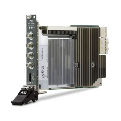
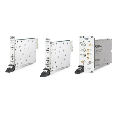
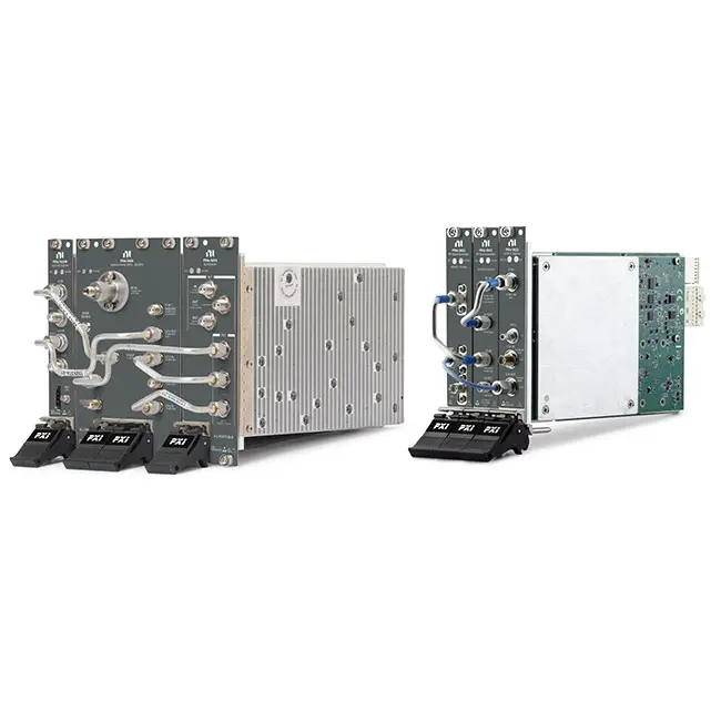
PXIe-5663 6.6 GHz PXI Vector Signal Analyzer
The NI PXIe-5663 is a modular PXI vector signal analyzer designed for automated RF measurements, wireless-device testing, spectrum monitoring and modulation analysis. Depending on the selected configuration, it provides frequency coverage up to 1.1 GHz, 3.4 GHz or 6.6 GHz.
The 6.6 GHz configuration combines an PXIe-5601 RF downconverter, an PXIe-5622 16-bit IF digitizer and a PXI-5652 RF signal generator operating as the local oscillator. The complete system delivers as much as 50 MHz of instantaneous bandwidth and is controlled as one analyzer through NI-RFSA software.
The PXIe-5663 is suitable for spectrum analysis, I/Q acquisition, wireless communication testing, RF component characterization and high-throughput production measurements. Its modular architecture also provides access to individual subsystem connections for advanced RF research and customized measurement systems.
Key Features of the PXIe-5663
- Modular PXI vector signal analyzer
- Frequency configurations up to 1.1 GHz, 3.4 GHz or 6.6 GHz
- 10 MHz to 6.6 GHz specified frequency range for the highest-frequency version
- Operation down to 1 MHz with specified limitations
- Up to 50 MHz equalized instantaneous bandwidth
- 16-bit IF digitization
- 150 MS/s maximum digitizer sample rate
- 64 MB or 256 MB onboard memory configurations
- Fully adjustable resolution bandwidth below 1 Hz to 10 MHz
- RF input levels up to +30 dBm under specified attenuation conditions
- 0 to 50 dB input attenuation in 1 dB steps
- Maximum continuous data transfer rate up to 300 MB/s
- External 10 MHz reference-clock support
- Flexible triggering and PXI synchronization
- NI-RFSA software support
- Suitable for spectrum and vector signal analysis
PXIe-5663 Technical Specifications
| Product Model | PXIe-5663 |
|---|---|
| Product Type | Modular PXI vector signal analyzer |
| Available Frequency Configurations | Up to 1.1 GHz, 3.4 GHz or 6.6 GHz |
| Specified Frequency Range | 10 MHz to the maximum frequency of the selected configuration |
| Extended Operation | Down to 1 MHz with limitations |
| Maximum Equalized Bandwidth | 50 MHz |
| Digitizer Resolution | 16 bits |
| Maximum Sample Rate | 150 MS/s |
| Onboard Memory | 64 MB or 256 MB |
| Resolution Bandwidth | Fully adjustable from below 1 Hz to 10 MHz |
| Amplitude Range | Average noise level to +30 dBm |
| Input Attenuation | 0 to 50 dB in 1 dB steps |
| RF Input Impedance | 50 Ω nominal |
| RF Input Coupling | AC coupled |
| RF Input Connector | SMA female |
| Maximum RF Input Power | +30 dBm with at least 8 dB attenuation; +20 dBm at 0 dB attenuation |
| Maximum DC Input | ±5 V nominal |
| Maximum Continuous Transfer Rate | 300 MB/s, system dependent |
| Internal Reference Frequency | 10 MHz |
| External Reference Input | 10 MHz, ±10 ppm |
| Frequency Tuning Resolution | 533 nHz |
| Warm-Up Time | 30 minutes |
| Calibration Interval | 1 year |
| Operating Temperature | 0°C to 55°C |
| Storage Temperature | −41°C to 71°C |
| Required Slots | Three slots for the complete analyzer |
| Combined Weight | Approximately 1.245 kg |
| Software Driver | NI-RFSA |
PXIe-5663 Frequency and Memory Configurations
| Part Number | Frequency Configuration | Onboard Memory |
|---|---|---|
| 780413-01 | 1.1 GHz RF vector signal analyzer | 64 MB |
| 780413-02 | 1.1 GHz RF vector signal analyzer | 256 MB |
| 780414-01 | 3.4 GHz RF vector signal analyzer | 64 MB |
| 780414-02 | 3.4 GHz RF vector signal analyzer | 256 MB |
| 780415-01 | 6.6 GHz RF vector signal analyzer | 64 MB |
| 780415-02 | 6.6 GHz RF vector signal analyzer | 256 MB |
Select the frequency and memory configuration according to the highest required carrier frequency, acquisition duration and waveform-processing requirements. The 256 MB versions can capture longer records than the corresponding 64 MB configurations.
PXIe-5663 Modular Architecture
The PXIe-5663 is a system-level product name rather than the model number printed on one physical module. The complete analyzer consists of an RF downconverter, a high-speed IF digitizer and an RF signal generator used as a local oscillator.
| Subsystem | Module | Function |
|---|---|---|
| RF Downconverter | PXIe-5601 | Converts the selected RF input band to an intermediate frequency |
| IF Digitizer | PXIe-5622 | Digitizes the IF signal at up to 150 MS/s with 16-bit resolution |
| Local Oscillator | PXI-5650, PXI-5651 or PXI-5652 | Provides the LO signal according to the selected frequency configuration |
The modules are linked using the specified SMA cables and associated in NI Measurement & Automation Explorer. NI-RFSA then controls the connected hardware as a single vector signal analyzer.
Equalized Instantaneous Bandwidth
The available equalized bandwidth depends on the analyzer’s center frequency. The maximum 50 MHz bandwidth is available through most of the upper tuning range.
| Center-Frequency Range | Equalized Bandwidth |
|---|---|
| 10 MHz to less than 120 MHz | 10 MHz |
| 120 MHz to less than 330 MHz | 20 MHz |
| 330 MHz to 6.6 GHz | 50 MHz |
Wide instantaneous bandwidth allows the analyzer to capture modulated RF signals and broad spectrum spans without retuning during each record. It also supports faster measurements when the signal of interest fits inside one acquisition bandwidth.
16-Bit IF Digitizer
The PXIe-5622 digitizes the intermediate-frequency signal with 16-bit resolution at rates up to 150 MS/s. Its digital downconverter provides selectable output bandwidths for wideband I/Q capture and narrower measurements.
Digital downconversion reduces the output sample rate when the complete 50 MHz bandwidth is not required. This can decrease data-transfer, memory and storage requirements while preserving the frequency band needed for analysis.
64 MB and 256 MB Memory Options
The PXIe-5663 is available with either 64 MB or 256 MB of onboard acquisition memory. Memory capacity affects the maximum waveform length that can be captured at a selected sample rate.
The 64 MB version is suitable for many spectrum and modulation measurements. The 256 MB version is preferable for longer I/Q records, intermittent-signal investigation, wireless-frame capture and applications that require additional pretrigger or post-trigger data.
RF Input and Attenuation
The analyzer provides a 50 Ω, AC-coupled SMA RF input. Programmable attenuation from 0 to 50 dB in 1 dB increments helps adapt the RF front end to different signal levels.
For maximum measurement sensitivity, lower attenuation can be used with low-level signals. Higher attenuation protects the input and improves large-signal handling. The programmed attenuation and applied signal must always remain within the applicable safe-input limits.
Noise and Dynamic-Range Performance
The PXIe-5663 provides a low average noise level for measuring weak RF signals. Typical noise performance depends on center frequency and analyzer configuration, with the lowest noise levels available through portions of the VHF and UHF ranges.
The analyzer also provides strong third-order intercept and residual-spur performance for separating smaller signals from larger adjacent carriers. Actual dynamic range depends on reference level, attenuation, bandwidth, averaging and the spectral relationship between the signals being measured.
Frequency Tuning and Measurement Speed
The analyzer is designed for fast automated measurements. Frequency settling can reach approximately 1.5 ms to within 0.1 ppm under applicable conditions, while amplitude settling can be as short as 62.5 µs when the mechanical attenuator does not change state.
Measurement throughput also depends on acquisition length, resolution bandwidth, averaging, data transfer, host-processor performance and analysis software. Narrow spans that fit within the instantaneous bandwidth can often be measured without repeated LO tuning.
I/Q Signal Acquisition
NI-RFSA can return time-domain complex I/Q data from the PXIe-5663. I/Q acquisition preserves the amplitude and phase information required for analyzing digitally modulated signals.
Captured data can be processed using compatible modulation-analysis software or custom LabVIEW, C or .NET applications. Engineers can measure characteristics such as signal power, occupied bandwidth, error vector magnitude, frequency error and modulation quality when supported by the selected analysis software.
Spectrum Analysis
The PXIe-5663 can perform frequency-domain measurements ranging from narrowband signal inspection to wideband spectrum capture. Adjustable resolution bandwidth enables engineers to balance frequency resolution, noise performance and measurement speed.
Typical measurements include channel power, adjacent-channel power, occupied bandwidth, harmonics, spurious signals and general spectrum monitoring. Measurement availability depends on the installed NI software and application configuration.
Triggering and Synchronization
The analyzer supports software, PXI and front-panel triggering for coordinating acquisitions with external events or other instruments. Reference clocks and PXI timing resources can be used to improve frequency coherence across a modular test system.
Triggering is valuable when capturing burst transmissions, frequency-hopping signals, pulsed RF events or a specific portion of a device operating cycle.
10 MHz Reference Clock
The PXIe-5663 includes a 10 MHz internal reference and can accept a compatible external 10 MHz reference. A shared reference clock allows the analyzer, signal generator and other RF instruments to operate from a common frequency source.
Reference-clock sharing is particularly useful for phase-sensitive measurements, long-duration testing and stimulus-and-response systems that require consistent frequency alignment.
Typical PXIe-5663 Applications
- RF spectrum analysis
- Vector signal analysis
- Complex I/Q waveform acquisition
- Wireless transmitter testing
- Modulation-quality measurements
- RF component characterization
- Automated production testing
- Spurious and harmonic measurements
- Adjacent-channel power testing
- Research and development
- Signal surveillance and spectrum monitoring
- Record-and-playback test systems
Wireless Transmitter Testing
The PXIe-5663 can capture and analyze digitally modulated signals generated by wireless transmitters. Its wide acquisition bandwidth supports measurement of complete channels and modulation spectra within the supported frequency range.
When combined with suitable analysis software, the system can evaluate transmitter power, spectral emissions, occupied bandwidth and modulation behavior. Required bandwidth, memory and frequency coverage should be verified against the wireless standard being tested.
Automated Production Testing
Fast tuning, wideband acquisition and PXI integration make the PXIe-5663 suitable for production test systems. A software-controlled sequence can configure the analyzer, acquire the RF signal, calculate measurement results and compare them with product limits.
Switching modules can route one analyzer among multiple devices under test, while shared clocks and triggers coordinate it with RF generators and other PXI instruments.
RF Record and Playback
Wideband I/Q data acquired by the PXIe-5663 can be transferred to the host computer or a suitable storage system. The recorded waveform can later be analyzed or reproduced using a compatible vector signal generator.
Record-and-playback systems are useful for capturing intermittent RF events, reproducing field signals and testing how receivers respond to realistic signal conditions.
NI-RFSA Software Support
The PXIe-5663 is controlled through the NI-RFSA instrument driver. NI-RFSA provides configuration, acquisition, triggering, calibration and data-fetching functions for supported programming environments.
The driver coordinates the separate hardware modules as a single analyzer. Applications can perform spectrum measurements or retrieve complex I/Q samples for customized signal processing.
LabVIEW Integration
LabVIEW applications can use NI-RFSA functions to set center frequency, reference level, acquisition bandwidth, sample rate, record length and trigger parameters. Measurement results can then be displayed, logged or passed to additional analysis routines.
The modular software architecture allows the PXIe-5663 to be integrated with PXI signal generators, switches, digitizers and digital instruments in a unified automated test program.
PXIe-5663 Installation Requirements
The complete analyzer occupies three chassis slots. Because the LO module in a PXIe-5663 is a PXI module, the selected chassis must provide a compatible PXI hybrid slot in addition to the PXI Express slots required by the PXIe-5601 and PXIe-5622.
Install the supplied intermodule SMA cables exactly as specified in the getting-started documentation. Configure the chassis fans for the required airflow, install filler panels in unused slots and allow at least 30 minutes of warm-up before calibrated measurements.
PXIe-5663 Troubleshooting
The PXIe-5663 does not appear as one analyzer
Confirm that the PXIe-5601, PXIe-5622 and correct PXI-5650-series LO module are all detected in NI MAX. Verify the intermodule cable connections, then associate the modules as one PXIe-5663 system.
The analyzer reports an LO or reference-lock error
Inspect the LO and reference cables and confirm that each cable is connected to the correct port. If an external reference is selected, verify that its frequency and signal level meet the analyzer requirements.
The measured signal level is incorrect
Check the reference level, input attenuation, center frequency and external cable loss. Confirm that the DUT signal does not exceed the RF input rating and allow the analyzer to complete its warm-up period.
The expected 50 MHz bandwidth is unavailable
The equalized bandwidth depends on center frequency. The maximum 50 MHz bandwidth applies from 330 MHz through 6.6 GHz, while lower-frequency tuning ranges provide 10 MHz or 20 MHz bandwidth.
Acquired records are too short
Reduce the acquisition sample rate or digital-downconversion bandwidth when the full bandwidth is unnecessary. For longer high-rate acquisitions, use a configuration equipped with 256 MB of onboard memory.
Continuous streaming is slower than expected
Check the PXI Express chassis, controller, storage device and host-processing performance. The stated maximum continuous transfer rate is system dependent and may be reduced by other devices sharing the data path.
The noise floor is higher than expected
Reduce input attenuation when safe, select an appropriate reference level and narrow the resolution bandwidth. Also inspect cables, shielding, grounding and nearby RF sources for external interference.
Modulation measurements are inconsistent
Verify the sample rate, acquisition bandwidth, reference clock, trigger configuration and analysis settings. Confirm that the entire modulated signal fits within the usable acquisition bandwidth at the selected center frequency.
PXIe-5663 vs PXIe-5663E
| Feature | PXIe-5663 | PXIe-5663E |
|---|---|---|
| RF Downconverter | PXIe-5601 | PXIe-5601 |
| IF Digitizer | PXIe-5622 | PXIe-5622 |
| 6.6 GHz Local Oscillator | PXI-5652 | PXIe-5652 |
| LO Platform | PXI | PXI Express |
| Chassis Consideration | Requires a compatible PXI hybrid slot for the LO | Uses a PXI Express LO module |
The primary architectural difference is the local-oscillator module. Select the version that matches the available chassis slots, existing hardware and required system configuration.
PXIe-5663 Comparison with Other NI RF Analyzers
| Model | General Configuration | Best Suited For |
|---|---|---|
| PXI-5661 | Earlier modular PXI vector signal analyzer | Legacy PXI RF measurement systems |
| PXIe-5663 | Up to 6.6 GHz and 50 MHz bandwidth | General-purpose wideband RF and wireless testing |
| PXIe-5663E | PXI Express LO version of the modular analyzer | Systems requiring a PXI Express local oscillator |
| PXIe-5665 | High-dynamic-range vector signal analyzer | Measurements prioritizing sensitivity and dynamic range |
| PXIe-5668 Series | Newer wideband microwave signal analyzers | Applications requiring higher frequencies or wider bandwidth |
Recommended Related Products
- PXIe-5601 RF Signal Downconverter
- PXIe-5622 16-Bit IF Digitizer
- PXI-5652 6.6 GHz RF Signal Generator
- PXIe-5663E Vector Signal Analyzer
- PXIe-5665 Vector Signal Analyzer
- PXIe-5668 Vector Signal Analyzer
- PXIe-5673 Vector Signal Generator
- View More NI PXI and PXI Express Modules
Selecting the Right PXIe-5663 Configuration
Choose the 1.1 GHz or 3.4 GHz version when the application is limited to lower-frequency RF signals and does not require 6 GHz coverage. Choose the 6.6 GHz configuration for WLAN, cellular, satellite, aerospace and general RF applications extending into the upper microwave range.
Select 64 MB memory for standard spectrum and shorter I/Q acquisitions. Choose 256 MB when longer waveform records, additional trigger history or high-rate modulation captures are required.
Why Choose the PXIe-5663?
- Provides frequency configurations extending to 6.6 GHz
- Captures as much as 50 MHz of instantaneous bandwidth
- Uses a 16-bit, 150 MS/s IF digitizer
- Supports spectrum and complex I/Q acquisition
- Offers programmable RF attenuation in 1 dB steps
- Provides 64 MB and 256 MB memory options
- Supports PXI triggers and external frequency references
- Integrates with NI-RFSA and LabVIEW
- Supports automated laboratory and production measurements
- Provides modular access to RF, IF and LO subsystems
Frequently Asked Questions
What is the PXIe-5663?
The PXIe-5663 is a modular PXI vector signal analyzer used for spectrum measurements, I/Q acquisition, wireless testing and automated RF signal analysis.
Is the PXIe-5663 one physical module?
No. PXIe-5663 is the system name for a multicomponent analyzer. A 6.6 GHz system combines the PXIe-5601 downconverter, PXIe-5622 digitizer and PXI-5652 local oscillator.
What is the maximum frequency?
The highest-frequency PXIe-5663 configuration covers specified input frequencies from 10 MHz to 6.6 GHz. Lower-frequency 1.1 GHz and 3.4 GHz configurations were also offered.
What is the instantaneous bandwidth?
The maximum equalized bandwidth is 50 MHz from 330 MHz through 6.6 GHz. The available bandwidth is 10 MHz below 120 MHz and 20 MHz from 120 MHz to below 330 MHz.
What digitizer does the PXIe-5663 use?
The system uses the PXIe-5622, a 16-bit IF digitizer with a maximum sample rate of 150 MS/s.
How much onboard memory is available?
PXIe-5663 configurations are available with either 64 MB or 256 MB of onboard acquisition memory.
Which software controls the PXIe-5663?
The analyzer is controlled through NI-RFSA. Compatible analysis toolkits and custom LabVIEW applications can process its spectrum or complex I/Q data.
Does the PXIe-5663 support an external reference clock?
Yes. It can use a compatible 10 MHz external frequency reference for synchronization with other instruments.
How many chassis slots are required?
The complete analyzer requires three slots. The standard PXIe-5663 uses two PXI Express modules and one PXI local-oscillator module, so a compatible hybrid slot is required.
What is the difference between the PXIe-5663 and PXIe-5663E?
The standard PXIe-5663 uses a PXI-5650-series local oscillator. The PXIe-5663E uses the corresponding PXI Express local-oscillator architecture.
What is the part number for the 6.6 GHz version?
Part number 780415-01 identifies the 6.6 GHz version with 64 MB memory, while 780415-02 identifies the 6.6 GHz version with 256 MB memory.
Request a Quote for the PXIe-5663
Contact us for current availability, configuration details, calibration options and project pricing for the NI PXIe-5663 Vector Signal Analyzer. We can also help identify compatible PXIe-5601, PXIe-5622 and PXI-5650-series modules, intermodule cables, chassis and RF signal generators for your test system.















