




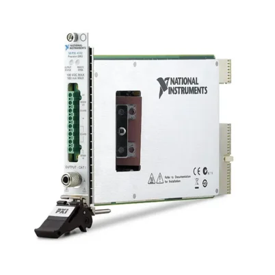
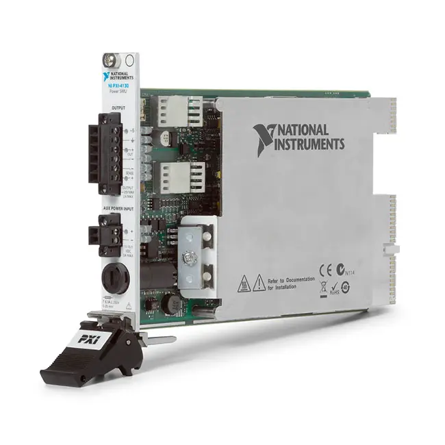
PXI-4130 ±20 V 40 W PXI Source Measure Unit
The PXI-4130 is a programmable PXI source measure unit designed for semiconductor characterization, component testing, battery testing and automated production systems. It combines a four-quadrant SMU channel with a separate utility power-supply channel in a compact, one-slot PXI module.
Channel 1 provides isolated voltage and current sourcing and measurement over ranges up to ±20 V and ±2 A. With the APS-4100 auxiliary power supply connected, the SMU can source as much as 40 W. Channel 0 supplies 0 V to 6 V at up to 1 A for powering auxiliary circuitry or providing an additional device bias.
Key Features of the PXI-4130
- Single isolated four-quadrant SMU channel
- Additional 0 V to 6 V utility power channel
- ±20 V and ±6 V SMU voltage ranges
- Maximum SMU current of ±2 A with auxiliary power
- Maximum source power of 40 W with auxiliary power
- Current ranges from 200 µA to 2 A
- 1 nA current measurement sensitivity
- Four-wire remote sensing on the SMU channel
- Source and sink operation in all four quadrants
- 3 kS/s maximum measurement rate
- 3,000 updates per second maximum output update rate
- Constant-voltage and constant-current operation
- 60 VDC channel-to-earth isolation, CAT I
- NI-DCPower driver support
- One-slot 3U PXI module
PXI-4130 Technical Specifications
| Product Model | PXI-4130 |
|---|---|
| Product Type | PXI source measure unit |
| SMU Channels | 1 isolated four-quadrant channel |
| Utility Channels | 1 unipolar power-supply channel |
| SMU Voltage Ranges | ±6 V and ±20 V |
| SMU Current Ranges | 200 µA, 2 mA, 20 mA, 200 mA and 2 A |
| Maximum SMU Source Current | ±2 A with a suitable auxiliary power supply |
| Maximum SMU Source Power | 40 W with auxiliary power |
| Internal-Power Limit | 2 W and 300 mA maximum on Channel 1 |
| Maximum Continuous Sink Power | 10 W, subject to temperature derating |
| Current Measurement Sensitivity | 1 nA |
| Maximum Measurement Rate | 3 kS/s |
| Maximum Output Update Rate | 3,000 updates/s |
| Typical SMU Settling Time | 500 µs under specified conditions |
| Remote Sense | Four-wire sensing with up to 1 V drop per lead |
| Utility Channel Output | 0 V to 6 V, up to 1 A and 6 W |
| Isolation | 60 VDC channel-to-earth, CAT I |
| Auxiliary Input | 11 VDC to 15.5 VDC, 5 A maximum |
| Front Connector | Six-position MINI-COMBICON output connector |
| Module Size | 3U, one-slot PXI/cPCI module |
| Dimensions | 2.0 cm × 13.0 cm × 21.6 cm |
| Weight | 312 g typical |
| Operating Temperature | 0°C to 55°C |
| Software Driver | NI-DCPower |
PXI-4130 Part Numbers and Power Configurations
| Item | Part Number | Description |
|---|---|---|
| PXI-4130 | 779647-30 | PXI-4130 power SMU without the APS-4100 auxiliary supply |
| PXI-4130 Kit | 779647-31 | PXI-4130 power SMU with APS-4100 auxiliary power supply |
| APS-4100 | Configuration dependent | Auxiliary power source used to obtain the full PXI-4130 output-current capability |
| Output Connector | Configuration dependent | Six-position MINI-COMBICON connector for Channel 0, Channel 1 and remote-sense wiring |
The two PXI-4130 ordering configurations should not be treated as electrically equivalent systems. The module can operate from PXI backplane power, but the APS-4100 or another compliant auxiliary supply is required when the application needs the full ±2 A and 40 W sourcing capability.
Two-Channel Power Architecture
The PXI-4130 contains one precision SMU channel and one utility power channel. Channel 1 is the isolated four-quadrant SMU, while Channel 0 provides a simpler unipolar output for powering support circuitry.
Channel 1 can source voltage, source current, measure voltage and measure current. Channel 0 can provide 0 V to 6 V at up to 1 A and can also measure its output voltage and current.
Four-Quadrant SMU Operation
The four-quadrant architecture allows Channel 1 to source or sink current at positive or negative output voltages. This means the PXI-4130 can operate as a programmable power source or as an electronic load within its output envelope.
Four-quadrant operation is useful for characterizing batteries, power-management devices, voltage regulators, diodes and other components that may either consume or return power during testing.
±20 V and ±2 A Output
The SMU channel provides ±6 V and ±20 V voltage ranges. Its five current ranges are 200 µA, 2 mA, 20 mA, 200 mA and 2 A, allowing the instrument to support both low-current measurements and higher-current device operation.
The full 2 A current range requires a suitable auxiliary power supply. When operating only from PXI backplane power, the SMU channel is limited to 2 W and no more than 300 mA.
40 W Source and 10 W Sink Capability
With the APS-4100 auxiliary supply, the PXI-4130 can source up to 40 W in its sourcing quadrants. This supports devices that require substantially more power than can be obtained from the PXI chassis backplane alone.
The continuous sinking capability is limited to 10 W and is subject to ambient-temperature derating. Test programs should monitor the operating point and avoid exceeding the applicable quadrant and thermal limits.
APS-4100 Auxiliary Power Supply
The APS-4100 provides the external energy required for full-power operation. The PXI-4130 accepts an auxiliary input between 11 VDC and 15.5 VDC, with a supply capacity of at least 60 W recommended for full-current applications.
An auxiliary-input LED shows whether the connected supply voltage is within the accepted range. However, the green indicator does not necessarily mean that auxiliary power is actively being used. Software can query the active power source through the NI-DCPower session.
1 nA Current Sensitivity
The 200 µA measurement range provides 1 nA resolution, enabling the PXI-4130 to measure standby current, leakage current and other relatively low-current device states.
For tests spanning low-current standby and higher-current active modes, software can select an appropriate range or use automatic ranging. Fixed ranges may provide more predictable timing in tightly controlled production sequences.
Four-Wire Remote Sensing
Channel 1 includes separate HI Sense and LO Sense connections for four-wire remote sensing. These connections allow the instrument to regulate voltage at the device under test instead of at the PXI-4130 front panel.
Remote sensing compensates for voltage drop in cables, connectors and fixture wiring. The PXI-4130 supports as much as 1 V of lead drop per sense lead under the specified power conditions.
6 V Utility Power Channel
Channel 0 supplies 0 V to 6 V at up to 1 A, with a maximum output power of 6 W. It can be used to power control logic, bias circuitry, relays, sensors or other supporting circuits required by the device under test.
The utility channel retains the same output capability whether the module uses internal or auxiliary power. It does not provide the bipolar, isolated four-quadrant operation available from Channel 1.
3 kS/s Measurement and Update Rates
The PXI-4130 supports a maximum measurement rate of 3 kS/s and a maximum output update rate of 3,000 updates per second. These rates support automated sweeps, device-response capture and production measurements.
Actual test throughput depends on averaging, selected ranges, aperture, settling time, load response and software sequencing. Precision measurements may require longer delays or additional averaging.
Constant-Voltage and Constant-Current Modes
In constant-voltage mode, the PXI-4130 regulates the programmed voltage while monitoring and limiting current. If the device reaches the programmed current limit, the channel enters constant-current operation.
In constant-current mode, the SMU regulates current while applying a voltage limit. Front-panel indicators identify constant-voltage, constant-current and error states, helping operators diagnose unexpected compliance conditions.
Typical PXI-4130 Applications
- Semiconductor component characterization
- Power-management IC testing
- Battery charge and discharge testing
- Voltage-regulator validation
- Diode and LED characterization
- Current-voltage curve tracing
- Leakage and standby-current measurement
- Consumer-electronics production testing
- Automotive electronic-component testing
- Research and laboratory automation
- Power sequencing and device biasing
- Automated functional testing
Semiconductor Characterization
The PXI-4130 can sweep voltage or current while recording the corresponding device response. This allows engineers to generate current-voltage curves for diodes, LEDs, transistors and power-management components.
Its multiple current ranges support measurements across different device operating states. Careful range selection, remote sensing and fixture design help improve measurement repeatability.
Battery Testing
Because Channel 1 can both source and sink current, the PXI-4130 can charge and discharge battery cells within its voltage, current, power and safety limits. Test software can record battery voltage and current during programmed operating sequences.
Battery testing requires external protection appropriate to the battery chemistry and energy capacity. The module’s current limit is not a substitute for fusing, thermal monitoring, isolation or a battery-management safety system.
Power Sequencing
The SMU and utility channels can provide separate supply rails for devices requiring multiple power inputs. Software can enable the outputs in a controlled sequence and measure current consumption during startup.
For deterministic multi-instrument systems, the PXI-4130 can be coordinated with additional SMUs, digital instruments and switching modules through PXI triggering and NI-DCPower programming.
NI-DCPower Software Support
The PXI-4130 is controlled through the NI-DCPower instrument driver. The driver provides functions for configuring voltage or current output, setting compliance limits, selecting ranges, measuring voltage and current, and controlling output state.
NI-DCPower supports LabVIEW, LabWindows/CVI and compatible text-based development environments. The same driver architecture is used by many newer NI PXI and PXI Express SMUs.
PXI System Integration
The PXI-4130 occupies one slot in a compatible 3U PXI or CompactPCI chassis. It can operate alongside digital multimeters, oscilloscopes, waveform generators, switching modules and data-acquisition instruments.
Before installation, verify chassis compatibility, available power, airflow and the required NI-DCPower version. High-power tests should use appropriate slot cooling and should remain within the module’s temperature-dependent sinking limits.
PXI-4130 Troubleshooting
The SMU cannot source 2 A
Confirm that the APS-4100 or another compliant 11 VDC to 15.5 VDC auxiliary source is connected. Without auxiliary power, Channel 1 is limited to 2 W and 300 mA.
The auxiliary-power LED is off
Check the auxiliary-supply voltage, polarity, connector wiring and front-panel fuse. The input must remain between 11 VDC and 15.5 VDC.
The channel enters current compliance
The load is requesting more current than the programmed current limit permits. Verify the DUT resistance, cable wiring, selected current range and configured compliance value.
The DUT voltage is lower than programmed
Check for voltage drop in the cables and fixture. Use four-wire remote sensing on Channel 1 and confirm that the sense leads are connected directly to the DUT terminals with the correct polarity.
The output is unstable
Review the load capacitance, output-capacitance setting, wiring inductance and control-loop conditions. Keep leads short and use the output-capacitance setting appropriate for the connected load.
Measurements contain excessive noise
Increase the number of samples averaged, improve shielding and grounding, and separate low-current measurement wiring from digital and high-current conductors. Allow the recommended 30-minute warm-up period for precision testing.
The output shuts down with an error
Check for overtemperature, excessive sink power, auxiliary-input faults and incorrect DUT connections. Allow the module to cool and verify that the operating point is inside the specified quadrant diagram.
The module is not detected in NI MAX
Confirm that the PXI-4130 is fully installed in a compatible slot. Check chassis power, controller communication and NI-DCPower installation, then rescan the system in NI Measurement & Automation Explorer.
PXI-4130 Comparison with Other NI SMUs
| Model | Primary Configuration | Best Suited For |
|---|---|---|
| PXI-4130 | ±20 V, ±2 A, 40 W SMU plus 6 V utility channel | Legacy PXI systems requiring moderate-voltage, higher-current sourcing |
| PXI-4132 | High-precision, low-current PXI SMU | Precision semiconductor and leakage-current measurements |
| PXIe-4136 | Single-channel, high-voltage PXI Express SMU | Devices requiring voltage up to approximately 200 V |
| PXIe-4138 | ±60 V, ±3 A precision system SMU | Modern semiconductor and mixed-signal production testing |
| PXIe-4145 | Four-channel precision PXI Express SMU | Parallel testing and devices requiring multiple bias rails |
PXI-4130 vs PXIe-4138
The PXI-4130 provides a ±20 V, ±2 A SMU channel and a separate 6 V utility output. The PXIe-4138 is a newer system SMU offering a wider voltage range, higher current capability and substantially greater low-current measurement sensitivity.
Choose the PXI-4130 when maintaining an existing PXI system or when its utility output and 40 W source capability meet the application. Choose the PXIe-4138 for newer PXI Express systems requiring greater precision, speed and voltage range.
PXI-4130 vs PXIe-4136
The PXIe-4136 is intended for higher-voltage device testing, while the PXI-4130 emphasizes current and source power at voltages up to ±20 V.
Select the PXIe-4136 for high-voltage semiconductor devices and insulation-related measurements. Select the PXI-4130 for lower-voltage devices that require current up to 2 A and source power up to 40 W.
PXI-4130 vs PXIe-4145
The PXI-4130 contains one four-quadrant SMU channel plus one utility output. The PXIe-4145 provides four precision SMU channels for devices requiring multiple independently controlled supply and measurement terminals.
The PXI-4130 is better suited to a single higher-power DUT connection. The PXIe-4145 is more appropriate for multi-rail components and parallel test architectures.
Recommended Related Products
- PXIe-4136 High-Voltage PXI Express Source Measure Unit
- PXIe-4138 ±60 V Precision System SMU
- PXIe-4145 Four-Channel Precision SMU
- PXIe-4139 High-Precision System SMU
- PXI-4110 Programmable Power Supply
- View More NI PXI and PXI Express Modules
Selecting the Right PXI Source Measure Unit
Choose the PXI-4130 when the application requires a four-quadrant ±20 V SMU, current up to ±2 A, source power up to 40 W and an additional 6 V utility channel in a legacy PXI platform.
For new systems, compare its performance with current PXI Express SMUs. Newer models can provide more channels, higher voltage, greater current sensitivity, faster sequencing and advanced transient-response control.
Why Choose the PXI-4130?
- Combines sourcing and measurement in one module
- Supports four-quadrant operation
- Sources up to ±20 V and ±2 A
- Provides up to 40 W with auxiliary power
- Includes a separate 6 V, 1 A utility channel
- Measures current with sensitivity down to 1 nA
- Supports four-wire remote sensing
- Provides 3 kS/s measurement and update rates
- Integrates with NI-DCPower and PXI test systems
Frequently Asked Questions
What is the PXI-4130?
The PXI-4130 is a programmable PXI source measure unit with one isolated four-quadrant SMU channel and one 0 V to 6 V utility power channel.
How many SMU channels does the PXI-4130 have?
It has one isolated SMU channel. The second output is a unipolar 6 V utility channel and is not another four-quadrant SMU.
What is the maximum PXI-4130 output?
With a suitable auxiliary supply, the SMU channel can output up to ±20 V, ±2 A and 40 W within its quadrant operating envelope.
Can the PXI-4130 operate without an APS-4100?
Yes, but Channel 1 is limited to 2 W and no more than 300 mA when powered only by the PXI backplane.
Can the PXI-4130 sink current?
Yes. The SMU channel supports four-quadrant source and sink operation. Continuous sinking power is limited to 10 W and is subject to thermal derating.
Does the PXI-4130 support remote sensing?
Yes. Channel 1 provides separate HI Sense and LO Sense connections for four-wire voltage regulation at the DUT.
What is the maximum sampling rate?
The maximum measurement rate is 3 kS/s. The maximum output update rate is also 3,000 updates per second.
What is the current measurement sensitivity?
The PXI-4130 provides current measurement resolution down to 1 nA on its 200 µA range.
Which software controls the PXI-4130?
The module is controlled through the NI-DCPower driver and can be integrated with LabVIEW, LabWindows/CVI and supported text-based programming environments.
What are the PXI-4130 ordering numbers?
Part number 779647-30 identifies the configuration without the APS-4100, while 779647-31 identifies the kit supplied with APS-4100 auxiliary power.
Request a Quote for the PXI-4130
Contact us for current availability, lead time and project pricing for the PXI-4130 ±20 V 40 W PXI Source Measure Unit. We can also help identify the required APS-4100 power configuration, output connectors, PXI chassis and suitable replacement SMUs.















