







Product Introduction
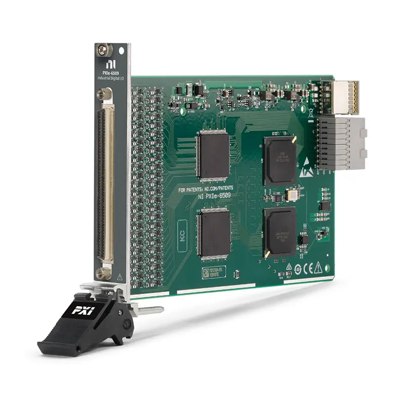
The PXIe‑6509 is a 96-channel, 5 V TTL/CMOS PXI Express digital I/O module designed for high-density device control, switch monitoring, relay operation, test-fixture control and automated functional testing.
Each digital line can be independently configured as an input or output. The module provides up to 24 mA of current drive per channel, allowing it to directly control compatible external digital devices such as solid-state relays and indicators.
The PXIe‑6509 also provides programmable power-up states, software-selectable pull-up or pull-down resistors, digital input filtering, change detection and a digital watchdog timer for controlled recovery from software or communication faults.
Product Overview
The National Instruments PXIe‑6509 belongs to the NI industrial digital I/O product family. Its standard NI part number is 787358‑01.
The module provides 96 bidirectional digital lines organized as 12 eight-bit ports. Each line can be used as a static digital input or output, while pull resistor settings are configurable by port.
A typical system architecture is:
Switches / Sensors / Relays / DUT ↔ PXIe‑6509 ↔ PXI Express Chassis ↔ PXI Controller ↔ NI‑DAQmx Application
The PXIe‑6509 is particularly useful when an automated test system requires a large number of software-controlled digital inputs and outputs within a single PXI Express slot.
Key Features
96 Bidirectional Digital I/O Channels
The PXIe‑6509 provides 96 bidirectional digital I/O channels.
The channels are organized as:
- 12 digital ports
- Eight digital lines per port
- 96 total software-configurable lines
The high channel density allows one module to monitor and control multiple switches, sensors, relays, indicators and DUT interface signals.
Independent Input and Output Configuration
Each digital line can be independently configured as an input or output.
This allows engineers to create mixed configurations such as:
- 64 digital inputs and 32 digital outputs
- 48 digital inputs and 48 digital outputs
- All 96 channels as digital inputs
- All 96 channels as digital outputs
- Application-specific combinations of input and output lines
The configuration can be adapted to the exact requirements of a test fixture or DUT interface.
5 V TTL/CMOS Compatibility
The PXIe‑6509 is designed for 5 V TTL/CMOS-compatible digital signals.
It can interface with compatible:
- Digital sensors
- Logic circuits
- Embedded controllers
- Test fixtures
- Solid-state relays
- Switches and push buttons
- Status indicators
- Electronic subsystems
The module uses single-ended, ground-referenced digital I/O and does not provide channel-to-channel isolation.
24 mA Output Drive
Each PXIe‑6509 digital output can provide up to 24 mA of current drive under the specified electrical conditions.
The higher drive capability allows the module to control compatible external devices such as:
- Solid-state relays
- LED indicators with appropriate current limiting
- Digital logic inputs
- Test-fixture control circuits
- Interface boards
- Low-current actuator-control inputs
The connected load must remain within the documented per-channel and total-device current limits.
Programmable Power-Up States
The PXIe‑6509 supports programmable digital power-up states.
The initial output state of each configured line can be defined in software as:
- Logic high
- Logic low
- Input state where supported
Programmable power-up states help ensure that connected relays, fixtures and control signals start in a known condition when the PXI system powers on or resets.
Software-Selectable Pull-Up and Pull-Down Resistors
Each eight-bit port can be configured with a software-selectable pull-up or pull-down resistor.
The typical resistor values are:
- 4.7 kΩ pull-up
- 47 kΩ pull-down
Pull resistors help prevent undriven input lines from floating and can establish a known default logic state when the external signal source is disconnected or in a high-impedance state.
Digital Input Filtering
The PXIe‑6509 provides programmable digital input filters.
Digital filtering can help:
- Reject short glitches
- Remove electrical spikes
- Debounce mechanical switches
- Debounce relay contacts
- Improve input-state stability
- Reduce false change-detection events
Filter settings should be selected according to the expected signal rate and the duration of unwanted transitions.
Digital Change Detection
The PXIe‑6509 supports digital change detection, allowing the module to notify the application when selected input lines change state.
This can reduce the need for continuous software polling in applications such as:
- Switch monitoring
- Alarm input detection
- Fixture-interlock monitoring
- DUT status monitoring
- Operator-control panels
- Digital event detection
The device provides one shared change-detection resource, so applications should normally combine required lines into a single change-detection task.
Digital I/O Watchdog Timer
The PXIe‑6509 includes a digital watchdog timer that can place output channels into configurable safe states if the controlling application stops communicating with the device.
A watchdog can help respond to:
- Application failure
- Operating-system failure
- Communication interruption
- Test-sequence timeout
- Unexpected software termination
The safe-state behavior must be configured and tested according to the requirements of the complete system.
Static Software-Timed Digital I/O
PXIe‑6509 digital input samples and digital output updates are software-timed.
The module is optimized for static and event-driven digital control rather than deterministic high-speed digital waveform acquisition or generation.
Typical uses include:
- Relay switching
- Switch-state monitoring
- Fixture control
- Test-mode selection
- DUT configuration
- Pass/fail indicator control
Fused 5 V Power Output
The PXIe‑6509 I/O connector provides a fused 5 V power output for compatible external circuits.
This auxiliary supply can simplify connections to low-power interface electronics, pull resistors and compatible digital accessories.
The total current drawn from the connector must remain within the documented limit.
Technical Specifications
| Parameter | Specification |
|---|---|
| Product Type | PXI Express Digital I/O Module |
| Model | PXIe‑6509 |
| Part Number | 787358‑01 |
| Manufacturer | National Instruments |
| Bus Interface | PXI Express |
| Digital I/O Channels | 96 Bidirectional Channels |
| Port Organization | 12 Ports, 8 Lines per Port |
| Direction Configuration | Independently Configurable by Line |
| Signal Type | Single-Ended, Ground Referenced |
| Logic Compatibility | 5 V TTL/CMOS |
| Output Current Drive | Up to 24 mA per Channel |
| Input Pull Configuration | Software-Selectable Pull-Up or Pull-Down by Port |
| Pull-Up Resistance | 4.7 kΩ Typical |
| Pull-Down Resistance | 47 kΩ Typical |
| Power-Up States | Programmable Input, Output High or Output Low |
| Digital Filtering | Programmable Input Filters |
| Change Detection | Supported |
| Watchdog Timer | Supported |
| Digital Timing | Software-Timed Static I/O |
| Data Transfer | Interrupts and Programmed I/O |
| I/O Connector | 100-Pin Female 0.050-Series SCSI |
| Connector Power Output | Fused 5 V Output |
| Isolation | Nonisolated |
| Recommended Cable | Compatible 100-Pin Shielded Cable |
| Software Driver | NI‑DAQmx |
| Primary Applications | Relay Control, Switch Monitoring, Fixture Control and Automated Test |
How Does the PXIe‑6509 Work?
The PXIe‑6509 provides a software-controlled interface between a PXI Express test system and external TTL/CMOS digital devices.
For digital input applications, the signal path is:
Switch / Sensor / DUT Output → PXIe‑6509 Digital Input → Change Detection or Software Read → PXI Controller
For digital output applications, the signal path is:
PXI Application → NI‑DAQmx → PXIe‑6509 Digital Output → Relay / Indicator / DUT Input
NI‑DAQmx configures line direction, power-up state, pull resistor, filtering, change detection and watchdog behavior.
96-Channel Port Architecture
The 96 channels are arranged as 12 eight-bit ports, typically identified as Port 0 through Port 11.
Each line can be configured as a static digital input or output, while pull-up and pull-down settings are selected for each eight-bit port.
This architecture provides both high channel density and flexible direction assignment for automated test systems.
Digital Input Applications
When configured as inputs, PXIe‑6509 lines can monitor the logic state of compatible external devices.
Typical input applications include:
- Mechanical switch monitoring
- Relay contact monitoring
- DUT status detection
- Fixture interlock monitoring
- Limit-switch acquisition
- Alarm and fault input monitoring
- Operator-panel input acquisition
- Production-line status monitoring
Digital filtering can be enabled when switch bounce or short noise pulses would otherwise cause incorrect state changes.
Digital Output Applications
When configured as outputs, PXIe‑6509 lines can control compatible digital loads and logic inputs.
Typical output applications include:
- Solid-state relay control
- Indicator control
- DUT mode selection
- Test-fixture switching
- Digital command generation
- Multiplexer control
- Power-sequencing control inputs
- Pass/fail status indication
The module is intended for static software-timed control. Applications requiring precise high-speed digital patterns should use a high-speed digital waveform or pattern instrument.
Direct Solid-State Relay Control
The 24 mA channel drive capability allows the PXIe‑6509 to directly control many compatible solid-state relay inputs.
Before connecting a solid-state relay, verify:
- Relay input voltage
- Required input current
- Turn-on and turn-off thresholds
- Polarity
- Common-ground requirements
- Total module current limits
Electromechanical relay coils generally require a suitable relay-driver circuit rather than direct connection to a PXIe‑6509 output.
Programmable Power-Up States
Power-up states allow output lines to enter defined logic conditions when the device initializes.
A typical configuration process is:
- Identify outputs connected to relays, actuators or DUT control inputs.
- Determine the safest initial logic state for each output.
- Configure the required power-up states in NI Measurement & Automation Explorer or NI‑DAQmx.
- Restart or reset the system.
- Verify the physical output states before connecting the final load.
Power-up states improve startup predictability but do not replace a complete system-level safety design.
Watchdog Safe States
The digital watchdog monitors communication between the application and the PXIe‑6509.
If the watchdog expires, selected outputs can transition to predefined states.
Possible watchdog states include:
- Logic low
- Logic high
- High-impedance or input state where supported
The watchdog timeout and expiration states should be selected according to the behavior required by the DUT, relays and test fixture.
Programmable Input Filtering
Mechanical switches and relay contacts can produce multiple transitions when changing state. Electrical interference can also create narrow input pulses.
The PXIe‑6509 input filter can reject transitions shorter than the configured filter interval.
This is useful for:
- Switch debouncing
- Relay-contact debouncing
- Glitch rejection
- Noise-pulse rejection
- Stable alarm monitoring
- Reliable fixture-state detection
A filter interval that is too long may reject valid input changes, so the setting must match the expected signal behavior.
Digital Change Detection
Change detection allows selected lines to generate an event when their state changes.
The application can monitor:
- Rising transitions
- Falling transitions
- Both rising and falling transitions
Change detection is useful when the application must respond to digital events without continuously reading all 96 lines.
Only one change-detection resource is available on the device. All required lines should therefore be configured within one compatible change-detection task.
Static vs High-Speed Digital I/O
| Feature | PXIe‑6509 Static DIO | High-Speed Digital Instrument |
|---|---|---|
| Channels | 96 | Model Dependent |
| Timing | Software-Timed | Hardware-Timed |
| Primary Use | Control and Status Monitoring | Waveform and Protocol Testing |
| Programmable Power-Up States | Supported | Model Dependent |
| Watchdog Timer | Supported | Model Dependent |
| Digital Filtering | Supported | Model Dependent |
| Best For | Relays, Switches and Fixtures | High-Speed Patterns and Buses |
Choose the PXIe‑6509 when the application needs high-density static control and monitoring. Choose a hardware-timed digital instrument when precise sample clocks or high-speed waveform generation are required.
Automated Functional Testing
The PXIe‑6509 can control and monitor multiple digital signals in an automated functional test system.
A typical test sequence may include:
- Initialize the PXI system and NI‑DAQmx tasks.
- Apply configured power-up and safe states.
- Verify fixture-interlock inputs.
- Set DUT operating modes through digital outputs.
- Activate compatible solid-state relays.
- Read DUT status outputs.
- Monitor alarm and fault lines.
- Record the digital states and pass/fail result.
- Return all outputs to defined safe states.
Production Test Applications
The high channel count makes the PXIe‑6509 suitable for production fixtures that require many low-speed control and status signals.
Potential production uses include:
- Fixture relay control
- DUT configuration
- Connector-presence detection
- Safety-interlock monitoring
- Pass/fail indicator control
- Barcode-station handshaking
- Production equipment status monitoring
- Automated test sequencing
Industrial Monitoring and Control
The PXIe‑6509 can monitor and control compatible 5 V TTL/CMOS industrial interface circuits.
Because the channels are nonisolated and ground referenced, external isolation or signal conditioning may be required when connecting to higher-voltage industrial sensors, long cables or devices with different ground potentials.
Semiconductor and Electronic Validation
The PXIe‑6509 can provide static control and monitoring signals for semiconductor and electronic device validation.
Potential uses include:
- Device mode selection
- Reset-line control
- Enable-signal control
- Status-bit monitoring
- Fixture relay operation
- Digital interlock monitoring
- Power-sequence control
- Automated functional verification
PXI Express System Integration
The PXIe‑6509 must be installed in a compatible PXI Express chassis.
A complete system normally requires:
- PXIe‑6509 digital I/O module
- Compatible PXI Express chassis
- Compatible PXI controller or remote-control connection
- Compatible 100-pin cable
- Terminal block or custom interface board
- NI‑DAQmx driver
- Compatible application software
Cables and Connector Accessories
The PXIe‑6509 uses a 100-pin female 0.050-series SCSI connector.
A complete wiring system may include:
- Compatible shielded 100-pin cable
- SCB-series connector block
- CB-series connector block
- Custom breakout board
- Relay interface board
- Appropriate grounding and shielding
Always confirm that the selected cable and connector block are specifically compatible with the PXIe‑6509 pinout.
System Integration Considerations
Before selecting the PXIe‑6509, verify:
- Required number of digital channels
- Required input and output allocation
- 5 V TTL/CMOS compatibility
- Required output current
- Need for isolation
- Need for hardware-timed operation
- Power-up state requirements
- Watchdog safe-state requirements
- Input filtering requirements
- Change-detection requirements
- PXI Express chassis compatibility
- Cable and connector requirements
- NI‑DAQmx compatibility
Current Drive Considerations
Although each channel can provide up to 24 mA under specified conditions, the total current used by all active outputs must remain within the module limits.
Before connecting loads:
- Check the current required by each load
- Calculate the total current for simultaneously active outputs
- Confirm output-high and output-low voltage requirements
- Use external driver circuits for higher-current loads
- Use appropriate flyback protection for inductive loads
- Avoid direct connection to relay coils unless specifically supported
Grounding and Isolation Considerations
The PXIe‑6509 uses single-ended, ground-referenced I/O and does not provide channel-to-channel isolation.
When connecting external equipment:
- Confirm that the grounds are compatible
- Avoid large ground-potential differences
- Use external isolation for remote equipment when necessary
- Keep cables appropriately short for the application
- Use shielded wiring in noisy environments
- Do not connect signals outside the documented voltage limits
Troubleshooting PXIe‑6509 Systems
If the PXIe‑6509 does not read or generate the expected digital states, check the hardware, wiring and software configuration.
- Verify that the module is detected in NI Measurement & Automation Explorer.
- Confirm that a compatible NI‑DAQmx driver is installed.
- Check the physical channel and port names.
- Verify that each line is configured for the correct direction.
- Confirm the external signal uses compatible TTL/CMOS levels.
- Check the ground connection between the module and DUT.
- Verify the selected pull-up or pull-down configuration.
- Temporarily disable input filtering when testing fast transitions.
- Check the configured power-up states.
- Verify watchdog timeout and expiration states.
- Confirm that only one change-detection task is active.
- Inspect the 100-pin cable and connector-block wiring.
- Test individual lines with NI‑MAX or a basic NI‑DAQmx example.
How to Choose a PXI Digital I/O Module
Before purchasing a PXI digital I/O module, determine:
- Required channel count
- Input-only, output-only or bidirectional operation
- Logic voltage requirements
- Output current requirements
- Static or hardware-timed operation
- Isolation requirements
- Power-up state requirements
- Watchdog requirements
- Digital filtering requirements
- Change-detection requirements
- PXI or PXI Express interface requirements
- Cable and terminal-block requirements
Industries
- Automated Test Equipment
- Electronics Manufacturing
- Semiconductor Test
- Electronic Design Validation
- Industrial Automation
- Automotive Testing
- Aerospace and Defense
- Research and Development
- Laboratory Automation
Applications
Solid-State Relay Control
The 24 mA output drive can directly control many compatible solid-state relay inputs.
Switch and Contact Monitoring
Digital inputs, pull resistors and filtering support reliable monitoring of switches, relay contacts and fixture interlocks.
Automated Test-Fixture Control
The 96 digital lines can control relay banks, DUT modes, indicators and other fixture functions.
DUT Status Monitoring
Change detection can identify transitions on selected alarm, ready, fault and status lines.
Power and Mode Sequencing
Programmable outputs can control compatible enable, reset and mode-selection inputs in an automated sequence.
Production Functional Test
High-density digital control and monitoring can be combined with other PXI instruments in automated production systems.
PXIe‑6509 vs PXI‑6509
| Feature | PXIe‑6509 | PXI‑6509 |
|---|---|---|
| Bus Interface | PXI Express | PXI |
| Digital I/O Channels | 96 | 96 |
| Logic Level | 5 V TTL/CMOS | 5 V TTL/CMOS |
| Output Drive | 24 mA | 24 mA |
| Direction Configuration | Independently by Line | Port Configurable |
| Software-Selectable Pull Resistors | Supported | Not Equivalent to PXIe Version |
| Part Number | 787358‑01 | Model Dependent |
| Recommended Use | Current PXI Express Systems | Legacy PXI Systems |
PXIe‑6509 vs PCIe‑6509
| Feature | PXIe‑6509 | PCIe‑6509 |
|---|---|---|
| Form Factor | PXI Express | Desktop PCI Express |
| Digital I/O Channels | 96 | 96 |
| Logic Compatibility | 5 V TTL/CMOS | 5 V TTL/CMOS |
| Output Drive | 24 mA | 24 mA |
| Power-Up States | Supported | Supported |
| Watchdog | Supported | Supported |
| Best For | Modular PXI Test Systems | Desktop Computers with PCIe Slots |
PXIe‑6509 vs Isolated Digital I/O Modules
| Feature | PXIe‑6509 | Isolated Digital I/O Module |
|---|---|---|
| Channel Count | 96 | Often Lower |
| Logic Level | 5 V TTL/CMOS | Model Dependent, Often Industrial Voltage |
| Isolation | No | Yes |
| Output Drive | 24 mA Logic Output | Model Dependent |
| Best For | High-Density Ground-Referenced Control | Industrial Signals and Different Ground Potentials |
Choose the PXIe‑6509 for high-density 5 V TTL/CMOS control. Choose an isolated digital I/O module when the application involves higher industrial voltages, long field wiring or significant ground-potential differences.
Software and Driver Requirements
The PXIe‑6509 uses the NI‑DAQmx driver for digital input, digital output and device configuration.
Compatible development environments can include:
- LabVIEW
- LabWindows/CVI
- C and C++
- .NET applications
- Python with a compatible NI‑DAQmx interface
- NI TestStand sequences through supported code modules
Verify NI‑DAQmx, operating-system and development-environment compatibility before installing or upgrading the system.
Recommended Related Products
| PCIe‑6509 | 96-channel PCI Express digital I/O device for compatible desktop computers. |
| USB‑6509 | 96-channel USB digital I/O device for portable and desktop test applications. |
| PXI‑6509 | Legacy PXI version of the 96-channel static digital I/O module. |
| PXI‑6515 | Industrial digital I/O module for applications requiring a different channel and electrical architecture. |
| PXI‑6528 | Isolated digital input and solid-state relay output module for industrial monitoring and control. |
| NI PXI Modules | Modular instruments for digital I/O, data acquisition, timing and automated test systems. |
Why Choose PXIe‑6509?
- 96 bidirectional digital I/O channels
- 12 eight-bit digital ports
- Independent input or output configuration by line
- 5 V TTL/CMOS compatibility
- Up to 24 mA drive per channel
- Direct control of compatible solid-state relays
- Programmable power-up states
- Software-selectable pull-up and pull-down resistors
- Programmable digital input filtering
- Digital change detection
- Digital watchdog timer
- Configurable watchdog safe states
- Fused 5 V connector power output
- PXI Express interface
- NI‑DAQmx software support
- Suitable for fixture and relay control
- Suitable for switch and status monitoring
- Suitable for automated production test
Frequently Asked Questions
What is the PXIe‑6509?
The PXIe‑6509 is a 96-channel, 5 V TTL/CMOS PXI Express digital I/O module with 24 mA output drive, programmable power-up states, filtering and watchdog support.
What is the part number for the PXIe‑6509?
The standard National Instruments part number for the PXIe‑6509 is 787358‑01.
How many digital channels does the PXIe‑6509 provide?
The module provides 96 bidirectional digital I/O channels organized as 12 eight-bit ports.
Can each PXIe‑6509 line be configured independently?
Yes. Each line can be independently configured as a static digital input or output.
Which logic levels does the PXIe‑6509 support?
The module is designed for compatible 5 V TTL/CMOS digital signals.
What is the maximum output current per channel?
Each output can provide up to 24 mA under the specified electrical and total-current limits.
Can the PXIe‑6509 directly control relays?
It can directly control many compatible solid-state relay inputs. Electromechanical relay coils normally require an external driver and flyback protection.
Does the PXIe‑6509 support programmable power-up states?
Yes. Output lines can be configured to start in predefined logic states when the device powers on or resets.
Does the PXIe‑6509 have a watchdog timer?
Yes. The watchdog can move configured output lines to predefined safe states if the controlling application stops communicating with the device.
Does the PXIe‑6509 support digital filtering?
Yes. Programmable input filters can reject glitches and debounce mechanical switches or relay contacts.
Does the PXIe‑6509 support change detection?
Yes. It can detect rising or falling transitions on selected digital input lines. The device has one shared change-detection resource.
Can the PXIe‑6509 generate hardware-timed digital waveforms?
No. Its digital input samples and output updates are software-timed. A high-speed digital instrument should be used for clocked waveform applications.
Does the PXIe‑6509 provide isolation?
No. The digital channels are single-ended and ground referenced. External isolation may be required for industrial signals or different ground potentials.
Does the PXIe‑6509 require a PXI Express chassis?
Yes. It must be installed in a compatible PXI Express chassis and controlled by an embedded controller or remote host connection.
Which driver does the PXIe‑6509 use?
The module uses the NI‑DAQmx driver.
What connector does the PXIe‑6509 use?
It uses a 100-pin female 0.050-series SCSI I/O connector.
What should I check before purchasing the PXIe‑6509?
Verify the required channel count, TTL/CMOS voltage compatibility, output current, isolation requirements, timing requirements, PXI Express chassis, cable, terminal block and NI‑DAQmx compatibility.
Conclusion
The PXIe‑6509 96-Channel Digital I/O Module provides high-density 5 V TTL/CMOS control and monitoring for PXI Express systems. Its 24 mA outputs, programmable power-up states, pull resistors, digital filtering, change detection and watchdog safe states make it suitable for solid-state relay control, switch monitoring, test-fixture automation, DUT configuration and production functional testing.















