






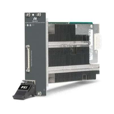
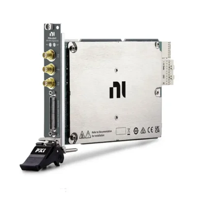

PXIe-6548 32-Channel 200 MHz Digital Waveform Instrument
Земля NI PXIe-6548 is a high-speed PXI Express digital waveform generator and analyzer designed for digital interface testing, protocol validation, device characterization and automated production test. It provides 32 bidirectional single-ended digital channels, a maximum sample clock rate of 200 МГц and data rates up to 400 Mbit/s per channel using double data rate operation.
With programmable output voltage levels from 1.2 V to 3.3 V, 100 mV voltage resolution, hardware comparison and per-bank timing adjustment, the PXIe-6548 can interface with a wide range of digital devices. Its PXI Express architecture also supports synchronization with oscilloscopes, waveform generators, source measure units and other PXI instrumentation.
PXIe-6548 Product Overview
The PXIe-6548 combines digital waveform generation and acquisition in a single one-slot PXI Express module. Each of its 32 digital channels can generate or acquire single-ended digital data, allowing one instrument to simulate digital interfaces, capture DUT responses and compare acquired data with expected patterns.
The module is particularly useful when a conventional static digital I/O device does not provide sufficient speed, timing control or waveform memory. Engineers can create custom digital patterns, define sample clocks, adjust timing relationships and perform hardware-based pass/fail comparisons through the NI-HSDIO driver.
Two primary memory configurations are available:
- 781012-02: 8 Mbit of onboard memory per channel
- 781012-03: 64 Mbit of onboard memory per channel
The correct memory option depends on the length of the generated and acquired waveforms, the number of script instructions and the amount of pattern reuse required by the test sequence.
Key Features of the PXIe-6548
32 Bidirectional Digital Channels
The PXIe-6548 provides 32 single-ended digital channels that can be configured for waveform generation or acquisition. This channel count supports byte-wide, word-wide and 32-bit digital interfaces while allowing unused channels to be assigned to control or status signals.
200 MHz Maximum Sample Clock
The module supports an onboard sample clock from 100 Hz to 200 MHz. External sample clocks can also be supplied through the front-panel CLK IN connector, while the STROBE input can be used as an acquisition clock for source-synchronous interfaces.
Up to 400 Mbit/s Per Channel
In SDR mode, the PXIe-6548 supports data rates up to 200 Mbit/s per channel. With DDR operation, data is transferred on both clock edges, increasing the maximum rate to 400 Mbit/s per channel at supported voltage levels.
The maximum DDR rate depends on the programmed logic voltage:
- 2.5 V to 3.3 V: up to 400 Mbit/s
- 1.8 V to 2.4 V: up to 375 Mbit/s
- 1.5 V to 1.7 V: up to 350 Mbit/s
- 1.2 V to 1.4 V: up to 300 Mbit/s
Programmable 1.2 V to 3.3 V Logic Levels
The generation voltage can be programmed from 1.2 V to 3.3 V in 100 mV increments. This flexibility helps the instrument communicate with devices using common 1.2 V, 1.5 V, 1.8 V, 2.5 V and 3.3 V digital logic.
Generation and acquisition sessions share a common voltage resource. When both functions operate simultaneously, they must use the same configured logic family.
Hardware Data Comparison
Hardware comparison allows the PXIe-6548 to compare acquired data with expected digital states as the test runs. This reduces the amount of captured data that must be transferred to the host and is useful for bit-error testing, interface validation and automated pass/fail decisions.
Per-Bank Digital Timing Adjustment
Digital channels are organized into timing banks that support programmable data delay. Engineers can adjust the timing relationship between channel groups and the sample clock to compensate for cable delay, fixture skew and DUT timing requirements.
Advanced Clocking and Synchronization
The PXIe-6548 can use its onboard clock, a front-panel external clock or an acquisition STROBE. It can also synchronize to the PXI Express backplane reference clock and export clock signals through front-panel connections.
Onboard Waveform Memory and Scripting
The instrument uses NI Synchronization and Memory Core architecture, where waveform data and script instructions share onboard memory. Scripting supports waveform sequencing, looping, branching and repeated pattern execution without requiring the host computer to continuously stream every sample.
PXIe-6548 Technical Specifications
| Product Model | NI PXIe-6548 |
|---|---|
| Product Type | Digital Waveform Generator/Analyzer |
| Bus and Form Factor | PXI Express, single-slot 3U module |
| Bidirectional Digital Channels | 32 |
| Signaling Type | Single-ended |
| Maximum Sample Clock Rate | 200 МГц |
| Maximum SDR Data Rate | 200 Mbit/s per channel |
| Maximum DDR Data Rate | 400 Mbit/s per channel |
| Generation Voltage Range | 1.2 V to 3.3 V |
| Voltage Programming Resolution | 100 mV |
| Input Impedance | 50 kΩ nominal |
| Input Protection | -1 V to 5 V |
| Onboard Clock Range | 100 Hz to 200 MHz |
| External CLK IN Range | 20 kHz to 200 MHz when used as a sample clock |
| STROBE Range | 100 Hz to 200 MHz |
| Programmable Function Interface | 4 PFI channels |
| Hardware Comparison | Supported |
| Onboard Memory | 8 Mbit/channel or 64 Mbit/channel |
| 8 Mbit/Channel Part Number | 781012-02 |
| 64 Mbit/Channel Part Number | 781012-03 |
| Clock Connections | SMA CLK IN and CLK OUT |
| Digital Interface Connector | Digital Data and Control connector |
| Driver | NI-HSDIO |
| Module Width | 1 PXI Express slot |
| Typical Power Consumption | 32.2 W |
| Warm-Up Time | 15 minutes |
How the PXIe-6548 Works
During waveform generation, digital patterns are transferred from the host computer to onboard memory. The PXIe-6548 then outputs the stored patterns using the selected sample clock, voltage level, data format and timing configuration.
During acquisition, the module samples the 32 digital channels using its onboard clock, the external CLK IN signal or the source-synchronous STROBE input. Acquired samples can be stored in onboard memory and transferred to the controller for analysis.
For validation applications, hardware comparison can evaluate the captured response against expected data while the pattern is running. Trigger and event routing can coordinate pattern generation, response acquisition and other instruments in the PXI system.
Clocking and Timing Options
Onboard Sample Clock
The internal sample clock offers a programmable range from 100 Hz to 200 MHz. It is suitable for internally timed pattern generation and acquisition when the DUT does not provide its own clock.
External CLK IN
The front-panel CLK IN connection can accept an external sample clock from 20 kHz to 200 MHz. It can also serve as a PLL reference clock at supported reference frequencies.
Source-Synchronous STROBE
For acquisition applications in which the DUT provides a clock or strobe alongside the data, the PXIe-6548 can use the DDC STROBE input as the sample clock. This helps maintain the timing relationship between the incoming data and the DUT-provided clock.
Clock Export
The instrument can export sample or reference clocks through the CLK OUT connection. A generation sample clock can also be routed through the digital interface connector, simplifying clock distribution to the DUT or test fixture.
Hardware Comparison and Bit-Error Testing
The PXIe-6548 supports real-time hardware comparison between acquired and expected data. Test developers can define expected logic states and identify mismatches without manually comparing every captured sample in host software.
This capability is valuable for:
- Bit-error detection
- Digital interface functional testing
- Register readback verification
- Memory device testing
- Protocol response validation
- Production pass/fail testing
Hardware comparison is intended for digital state evaluation. The PXIe-6548 does not include a per-pin parametric measurement unit or active-load circuitry, so applications requiring DC current measurements or semiconductor pin electronics should consider a digital pattern instrument.
Typical PXIe-6548 Applications
- High-speed digital interface testing
- Custom digital protocol generation and analysis
- Serial-to-parallel and parallel bus validation
- Memory device functional testing
- FPGA and ASIC interface verification
- Embedded controller testing
- Digital sensor emulation
- Bit-error and data-integrity testing
- Mixed-signal device characterization
- Hardware-in-the-loop digital stimulus and capture
- Automated production test
- Research and laboratory validation
PXIe-6548 for Protocol Testing
Because the PXIe-6548 is a waveform-based instrument, engineers can define digital patterns for proprietary or nonstandard interfaces instead of relying on a fixed protocol implementation. Timing, direction, voltage and expected response data can be controlled through software.
The instrument is well suited to parallel and source-synchronous buses within its channel, voltage and timing limits. Protocol encoding, decoding and transaction control are typically implemented in the host application or through predefined waveform scripts.
PXIe-6548 in Mixed-Signal Test Systems
Many devices require digital control signals together with analog stimulus and measurement. Installed in a PXI Express chassis, the PXIe-6548 can operate alongside oscilloscopes, arbitrary waveform generators, digital multimeters, RF instruments and programmable power supplies.
PXI trigger lines and the 100 MHz backplane reference clock help coordinate multiple instruments. This architecture enables synchronized digital stimulus, analog acquisition and automated device evaluation in one modular system.
PXIe-6548 Memory Selection
781012-02 with 8 Mbit per Channel
The 8 Mbit/channel version is suitable for many functional tests, repeating protocol patterns and applications that use short or reusable waveforms. It can be the practical choice when deep pattern storage is not required.
781012-03 with 64 Mbit per Channel
The 64 Mbit/channel version provides greater storage capacity for long digital sequences, extended acquisitions and tests containing many unique waveform segments. It is generally preferred when pattern length may increase during future development.
Because scripts and waveform data share onboard memory, actual usable sample depth depends on the selected data width, waveform organization and number of script instructions.
PXIe-6548 Software Support
The PXIe-6548 is controlled through the NI-HSDIO instrument driver. NI-HSDIO provides configuration, waveform generation, acquisition, triggering, scripting and hardware-comparison functions.
Supported development environments include:
- ЛабВью
- LabWindows/CVI
- Measurement Studio
- Microsoft Visual C/C++
- .NET languages including C# and Visual Basic .NET
NI Measurement & Automation Explorer can be used to detect the module, view device information, configure the system and perform initial troubleshooting.
PXIe-6548 System Requirements
A complete PXIe-6548 system normally requires:
- A compatible PXI Express chassis
- An embedded PXI controller or external computer interface
- NI-HSDIO driver software
- A compatible digital data cable
- A breakout, terminal block or custom interface fixture
- Optional clock and trigger cables
- Application development software
NI specifies performance using a 1 m cable and recommends the SHC68-C68-D4 for applicable connections. Longer cables and unsuitable fixtures can reduce signal quality at high data rates.
PXIe-6548 Signal-Integrity Considerations
Operation at hundreds of megabits per second requires careful attention to cable length, impedance, grounding, termination and fixture design. A digital pattern that works at a low rate may become unreliable as edge timing and channel skew consume more of the available timing margin.
For reliable results:
- Use short, compatible high-speed digital cables
- Maintain controlled impedance through the fixture
- Provide a low-inductance ground connection
- Avoid unterminated stubs and unnecessary adapters
- Match the programmed voltage to the DUT logic family
- Use per-bank delay to compensate for known timing offsets
- Validate the waveform at the DUT connection point
PXIe-6548 Comparison with Related Instruments
| Модель | Каналы | Maximum Clock Rate | Maximum Data Rate | Hardware Compare | General Positioning |
|---|---|---|---|---|---|
| PXIe-6544 | 32 | 100 MHz | 100 Mbit/s | No | Standard-voltage digital interfacing |
| PXIe-6545 | 32 | 200 МГц | 200 Mbit/s | No | Faster standard-voltage digital interfacing |
| PXIe-6547 | 32 | 100 MHz | 200 Mbit/s with DDR | Да | Programmable-voltage waveform testing |
| PXIe-6548 | 32 | 200 МГц | 400 Mbit/s with DDR | Да | Higher-speed programmable-voltage waveform testing |
| PXIe-6556 | 24 | 200 МГц | 200 Mbit/s | Да | Digital waveform testing with wider voltage capability and PMU functions |
| PXIe-6571 | 32 | 100 MHz class | Digital pattern operation | Да | Semiconductor test with per-pin parametric features |
PXIe-6548 vs PXIe-6547
The PXIe-6547 and PXIe-6548 both provide 32 bidirectional channels, programmable 1.2 V to 3.3 V logic levels and hardware comparison. The primary difference is speed.
The PXIe-6547 has a maximum sample clock rate of 100 MHz and supports up to 200 Mbit/s with DDR. The PXIe-6548 increases the maximum clock rate to 200 MHz and supports up to 400 Mbit/s with DDR. Choose the PXIe-6548 when the DUT requires higher data throughput or additional timing margin.
PXIe-6548 vs Digital Pattern Instruments
The PXIe-6548 is a digital waveform generator/analyzer controlled by NI-HSDIO. It is optimized for waveform-based interface testing and does not contain a per-pin parametric measurement unit or active-load circuitry.
A digital pattern instrument such as the PXIe-6571 is better suited to semiconductor validation and production test that requires pin electronics, per-pin voltage configuration, DC parametric measurements or digital pattern workflows. The appropriate choice depends on whether the application primarily requires flexible high-speed waveforms or semiconductor-oriented pin resources.
Recommended Related Products
- PXIe-6547 – 32-channel digital waveform instrument for applications requiring lower clock and data rates.
- PXIe-6545 – 200 MHz digital instrument for standard-voltage interface testing without hardware comparison.
- PXIe-6556 – 24-channel high-speed digital waveform instrument with a broader voltage range and parametric measurement capability.
- PXIe-6571 – digital pattern instrument for semiconductor characterization and production test.
- PXIe-1085 – high-bandwidth PXI Express chassis for multi-instrument automated test systems.
- PXIe-8880 – embedded PXI Express controller for computationally demanding test applications.
PXIe-6548 Selection Guidance
Before selecting the PXIe-6548, verify the following requirements:
- The DUT uses single-ended digital signaling
- No more than 32 bidirectional data channels are required
- The required logic voltage is between 1.2 V and 3.3 V
- The required sample clock does not exceed 200 MHz
- The required DDR data rate is supported at the selected voltage
- The application does not require active-load or per-pin PMU functions
- The selected memory version can store the required patterns
- The chassis provides a compatible PXI Express peripheral slot
- The cable and fixture can maintain signal integrity at the target rate
Common PXIe-6548 Troubleshooting Checks
The Module Is Not Detected
Confirm that the chassis and controller are powered correctly, the module is fully seated in a compatible PXI Express slot and a supported NI-HSDIO driver version is installed. Use NI MAX to check whether the hardware appears and passes a self-test.
Acquired Data Contains Unexpected Errors
Verify the voltage family, sampling edge, clock source and data direction. Inspect cable length, grounding and fixture impedance. Per-bank data delay may be required to center the acquisition point within the valid data window.
Generation Does Not Match the DUT Voltage
Check the programmed generation voltage and confirm that simultaneous generation and acquisition sessions use compatible voltage settings. Measure the voltage at the DUT because loading and fixture losses can affect the observed signal.
External Clocking Is Unstable
Confirm that the external clock meets the required amplitude, frequency and duty-cycle limits. Use proper 50 Ω cabling for the SMA clock connection and verify whether the configured input impedance is appropriate for the clock source.
Waveform Memory Is Insufficient
Reduce duplicate waveform data by using scripts, loops and reusable waveform segments. If the test requires long nonrepeating patterns or extended acquisitions, select the 64 Mbit/channel version.
Frequently Asked Questions
What is the PXIe-6548 used for?
The PXIe-6548 generates, acquires and compares high-speed digital waveforms. Typical uses include protocol testing, FPGA interface validation, memory testing, embedded device characterization and automated functional test.
How many digital channels does the PXIe-6548 provide?
It provides 32 bidirectional single-ended digital channels.
What is the maximum clock rate?
The maximum onboard sample clock rate is 200 MHz.
What is the maximum data rate?
The maximum rate is 200 Mbit/s per channel in SDR mode and up to 400 Mbit/s per channel in DDR mode. The maximum DDR rate varies with the selected voltage level.
Which logic voltages are supported?
The generation voltage is programmable from 1.2 V to 3.3 V in 100 mV increments.
Does the PXIe-6548 support hardware comparison?
Yes. It can compare acquired data with expected states in hardware for bit-error detection and functional pass/fail testing.
Does the PXIe-6548 include a PMU?
No. The PXIe-6548 does not include a per-pin parametric measurement unit or active-load circuitry.
What are the PXIe-6548 part numbers?
Part number 781012-02 provides 8 Mbit of memory per channel, while part number 781012-03 provides 64 Mbit per channel.
Which software driver controls the PXIe-6548?
The module is controlled using the NI-HSDIO driver.
Can the PXIe-6548 use an external sample clock?
Yes. An external sample clock can be supplied through CLK IN. The STROBE connection can also provide the sample clock for acquisition applications.
Can the PXIe-6548 operate without a PXI chassis?
No. It requires a compatible PXI Express chassis and either an embedded controller or an external computer connection.
Why Choose the PXIe-6548?
The PXIe-6548 is a strong choice for engineers who need more capability than conventional digital I/O but do not require semiconductor-focused digital pattern instrumentation. It combines 32 bidirectional channels, programmable voltage levels, high-speed DDR operation, hardware comparison and flexible clocking in a compact PXI Express module.
Its ability to synchronize with other PXI instruments makes it suitable for integrated digital and mixed-signal test systems used in design validation, characterization and production environments.
Request a Quote for the PXIe-6548
Contact us for current availability, lead time and project pricing for the NI PXIe-6548 Digital Waveform Instrument. Please specify whether your application requires the 8 Mbit/channel version, part number 781012-02, or the 64 Mbit/channel version, part number 781012-03.
We can also help identify compatible PXI Express chassis, controllers, high-speed digital cables and related instruments for your automated test system.















